


1 Introduction
Birkhoff sections are a classical tool for studying flows on 3-manifolds, appearing back in the early
 $20$
th century in the work of Poincare and Birkhoff. They can be used to reduce questions about the dynamics of three-dimensional flows to dynamics of surface homeomorphisms. See [Reference FranksFra92, Reference Hofer, Wysocki and ZehnderHWZ98] for two classical applications. The question of when a flow has a Birkhoff section, especially when the flow is a Reeb flow, is still a popular research topic. See [Reference Colin, Dehornoy, Hryniewicz and RechtmanCDHR22, Reference Contreras and MazzucchelliCM22] for some recent progress.
$20$
th century in the work of Poincare and Birkhoff. They can be used to reduce questions about the dynamics of three-dimensional flows to dynamics of surface homeomorphisms. See [Reference FranksFra92, Reference Hofer, Wysocki and ZehnderHWZ98] for two classical applications. The question of when a flow has a Birkhoff section, especially when the flow is a Reeb flow, is still a popular research topic. See [Reference Colin, Dehornoy, Hryniewicz and RechtmanCDHR22, Reference Contreras and MazzucchelliCM22] for some recent progress.
One class of flows which is long known to admit Birkhoff sections are Anosov flows, which were introduced by D. V. Anosov back in the 1960s. This result is due to work of Fried in [Reference FriedFri83]. The class of Anosov flows was later expanded to the class of pseudo-Anosov flows by Thurston for wider applicability in the study of 3-manifold topology, and Brunella generalized Fried’s result to this larger class of flows in [Reference BrunellaBru95].
Theorem 1.1. [Reference BrunellaBru95, Reference FriedFri83]
Let
 $\phi $
be a transitive pseudo-Anosov flow on a closed 3-manifold. Then
$\phi $
be a transitive pseudo-Anosov flow on a closed 3-manifold. Then
 $\phi $
has a Birkhoff section.
$\phi $
has a Birkhoff section.
One unsatisfying feature of Fried’s and Brunella’s proofs of Theorem 1.1, however, is that they are compactness arguments: roughly, the proofs go by constructing small local transverse surfaces, using compactness to argue that finitely many of these cover up the flow, then piecing them together. As a result, one has no control over how complicated the Birkhoff section is.
In this paper, we present a new method of constructing Birkhoff sections for pseudo-Anosov flows which does allow for control over the complexity. This method uses the recent technology of veering triangulations and their connection with pseudo-Anosov flows: roughly, given a pseudo-Anosov flow on an oriented closed 3-manifold, there exists a veering triangulation whose faces are positively transverse to the flow.
The idea is to construct transverse surfaces to the flow using the combinatorics of the triangulation. By piecing these surfaces together and resolving the self-intersections, we get a Birkhoff section to the flow. The control over the complexity comes from the fact that the combinatorics of the triangulation can be explicitly described, which allows for control over the constructed transverse surfaces. Our main result is that it is always possible to arrange for the final Birkhoff section to have two boundary components.
Theorem 1.2. Let
 $\phi $
be a transitive pseudo-Anosov flow on a closed 3-manifold. Then
$\phi $
be a transitive pseudo-Anosov flow on a closed 3-manifold. Then
 $\phi $
has a Birkhoff section with two boundary components, where each boundary component is embedded along a closed orbit of
$\phi $
has a Birkhoff section with two boundary components, where each boundary component is embedded along a closed orbit of
 $\phi $
.
$\phi $
.
Theorem 1.2 follows from the more technical Theorem 6.4 which, in addition, gives explicit bounds on the Euler characteristic of the Birkhoff section as well as the complexity of its boundary components.
For the rest of this introduction, we discuss the context of Theorem 1.2 within the literature of pseudo-Anosov flows, describe some ideas in the proof of Theorem 1.2, and provide an outline of the paper.
1.1 Context for ‘two boundary components’
In [Reference ThurstonThu97, p. 57], Thurston asks for a description of ‘the minimal collections of orbits that need to be removed for the [pseudo-Anosov] flow to admit a section’. Theorem 1.2 can be seen as some progress toward this: for a general pseudo-Anosov flow, a minimal collection with the least number of elements will have two orbits. In fact, Theorem 1.2 gives slightly more since it asserts that one can find a Birkhoff section with one boundary component embedded along each of two closed orbits.
In the case of Anosov flows, Marty recently showed that an Anosov flow admits a Birkhoff section with only one boundary component if and only if it is skew
 $\mathbb {R}$
-covered ([Reference MartyMar21, Theorem G], [Reference MartyMar23, Theorem E]). Together with Theorem 1.2, this provides the following neat trichotomy for Anosov flows:
$\mathbb {R}$
-covered ([Reference MartyMar21, Theorem G], [Reference MartyMar23, Theorem E]). Together with Theorem 1.2, this provides the following neat trichotomy for Anosov flows:

See also [Reference MartyMar23, Table 1].
In particular, since plenty of non-
 $\mathbb {R}$
-covered Anosov flows are known to exist (see, for example [Reference Bonatti and IakovoglouBI23]), this shows that Theorem 1.2 is sharp. This also gives an exact classification of Anosov flows for which Theorem 1.2 is sharp.
$\mathbb {R}$
-covered Anosov flows are known to exist (see, for example [Reference Bonatti and IakovoglouBI23]), this shows that Theorem 1.2 is sharp. This also gives an exact classification of Anosov flows for which Theorem 1.2 is sharp.
1.2 Veering triangulations
We review some key points from the theory of veering triangulations to explain some ideas in the proof of Theorem 1.2. See §§2.3, 3, and 4 for more details.
Let
 $\phi $
be a pseudo-Anosov flow on an oriented closed 3-manifold M. Let
$\phi $
be a pseudo-Anosov flow on an oriented closed 3-manifold M. Let
 $\mathcal {C}$
be a collection of closed orbits satisfying the technical condition that
$\mathcal {C}$
be a collection of closed orbits satisfying the technical condition that
 $\phi $
has no perfect fits relative to
$\phi $
has no perfect fits relative to
 $\mathcal {C}$
; we show that such a collection always exists when
$\mathcal {C}$
; we show that such a collection always exists when
 $\phi $
is transitive.
$\phi $
is transitive.
Proposition 2.7. Let
 $\phi $
be a transitive pseudo-Anosov flow on a closed 3-manifold. There exists a collection of orbits
$\phi $
be a transitive pseudo-Anosov flow on a closed 3-manifold. There exists a collection of orbits
 $\mathcal {C}$
such that
$\mathcal {C}$
such that
 $\phi $
is without perfect fits relative to
$\phi $
is without perfect fits relative to
 $\mathcal {C}$
. In fact,
$\mathcal {C}$
. In fact,
 $\mathcal {C}$
can be chosen to be the set of singular orbits and one other orbit.
$\mathcal {C}$
can be chosen to be the set of singular orbits and one other orbit.
The main result is then that there exists a veering triangulation on the cusped manifold
 $M \backslash \bigcup \mathcal {C}$
. Moreover, the
$M \backslash \bigcup \mathcal {C}$
. Moreover, the
 $2$
-skeleton of the triangulation is positively transverse to
$2$
-skeleton of the triangulation is positively transverse to
 $\phi $
and the combinatorics of the triangulation encodes the dynamics of the flow.
$\phi $
and the combinatorics of the triangulation encodes the dynamics of the flow.
The existence of the triangulation is the unpublished work of Agol-Guéritaud, while transversality of the
 $2$
-skeleton is due to Landry, Minsky, and Taylor [Reference Landry, Minsky and TaylorLMT22]. To achieve this, they had to show that one can place the edges appropriately while constructing the triangulation. An important point for us is that there is no canonical choice for this placement of edges, and we shall use this freedom to construct some transverse surfaces to the flow.
$2$
-skeleton is due to Landry, Minsky, and Taylor [Reference Landry, Minsky and TaylorLMT22]. To achieve this, they had to show that one can place the edges appropriately while constructing the triangulation. An important point for us is that there is no canonical choice for this placement of edges, and we shall use this freedom to construct some transverse surfaces to the flow.
1.3 Method of constructing Birkhoff sections
We introduce the notion of a broken transverse surface to a flow. These are surfaces which have a vertical boundary and a horizontal boundary. The vertical boundary is tangent to the flow whereas the interior of the surface and the horizontal boundary are transverse to the flow. See Definition 2.19 for details. Provided that their horizontal boundaries match up, one can glue up a collection of broken transverse surfaces into a transverse surface that only has vertical boundary. If in addition every orbit meets one of the broken transverse surfaces in finite time, then the glued up transverse surface would be a Birkhoff section.
For a given pseudo-Anosov flow
 $\phi $
, we construct two types of broken transverse surfaces out of the combinatorial data of an associated veering triangulation
$\phi $
, we construct two types of broken transverse surfaces out of the combinatorial data of an associated veering triangulation
 $\Delta $
.
$\Delta $
.
The first type of surfaces is helicoids. We construct these from winding edge paths, which are edge paths in the universal cover
 $\widetilde {\Delta }$
that wind around an orbit. The vertical boundary of such a helicoidal surface is the orbit that the edge path winds around, while the horizontal boundary is the collection of edges in the edge path (see Figure 28). It is here that the edge placements mentioned in the previous subsection come up. We have to argue that we can arrange for this winding behavior to occur where we expect it to. This is done in a fairly technical trace through Landry, Minsky, and Taylor’s work in §3.
$\widetilde {\Delta }$
that wind around an orbit. The vertical boundary of such a helicoidal surface is the orbit that the edge path winds around, while the horizontal boundary is the collection of edges in the edge path (see Figure 28). It is here that the edge placements mentioned in the previous subsection come up. We have to argue that we can arrange for this winding behavior to occur where we expect it to. This is done in a fairly technical trace through Landry, Minsky, and Taylor’s work in §3.
The second type of surfaces comes from the shearing decomposition of veering triangulations, introduced by Schleimer and Segerman in [Reference Schleimer and SegermanSS]. These surfaces are obtained by putting together faces of the triangulation, and essentially have no vertical boundary. See §6.1 for details.
For the proof of Theorem 6.4, we first choose sufficiently many surfaces of the second type to intersect all the orbits, then show that we can construct two helicoids with matching horizontal boundary. This allows us to glue the surfaces up into an immersed Birkhoff section. A standard trick of Fried [Reference FriedFri83] then allows us to resolve the self-intersections and get an honest Birkhoff section. The boundary of this Birkhoff section comes from the vertical boundary of the two helicoids, and hence consists of exactly two closed orbits.
In our construction, we will also keep track of the complexity of the various objects involved, so as to obtain the explicit bounds in Theorem 6.4. The reader who is ultimately only interested in Theorem 1.2 can skip these parts.
1.4 Outline of the paper
In §2, we recall some background knowledge about pseudo-Anosov flows, Birkhoff sections, and veering triangulations. In §3, we recall the construction in [Reference Landry, Minsky and TaylorLMT22] of the veering triangulation associated to a pseudo-Anosov flow, explaining how we can arrange for winding edge paths along the way. In §4, we recall work in [Reference Landry, Minsky and TaylorLMT22] on encoding closed orbits of the flow using the dual graph and flow graph of the veering triangulation. This is so that we can define the flow graph complexity of closed orbits and establish some lemmas for keeping track of complexities.
In §5, we explain how to construct the helicoidal broken transverse surfaces as mentioned above. The construction goes through objects which we call edge sequences. These lift up to winding edge paths in the universal cover which bound the desired helicoids. In §6, we recall the shearing decomposition, and we prove Theorems 6.3 and 6.4. In §7, we include some extra discussion of our theorems and present some future questions coming out of this paper.
1.5 Notational conventions
Throughout this paper, we will use the following notation.
-
•
 $X {\backslash \!\backslash } Y$
will denote the metric completion of
$X \backslash Y$
with respect to the induced path metric from X. In addition, we will call the components of
$X {\backslash \!\backslash } Y$
the complementary regions of Y in X.
$X {\backslash \!\backslash } Y$
will denote the metric completion of
$X \backslash Y$
with respect to the induced path metric from X. In addition, we will call the components of
$X {\backslash \!\backslash } Y$
the complementary regions of Y in X. -
•
$\widetilde {X}$
will denote the universal cover of X, unless otherwise stated. -
• Suppose
$\alpha $
is a path, then
$-\alpha $
will denote the path traversed in the opposite direction. -
• Suppose
$\alpha $
and
$\beta $
are paths, where the ending point of
$\alpha $
equals to the starting point of
$\beta $
, then
$\alpha * \beta $
will denote the concatenated path obtained by traversing
$\alpha $
then
$\beta $
. -
• Suppose
$\mathcal {C}$
is a collection of sets, then
$\bigcup \mathcal {C}$
will denote the union over all elements of
$\mathcal {C}$
.


2 Background
2.1 Pseudo-Anosov flows
We recall the definition of a pseudo-Anosov flow.
Definition 2.1. Let
 $n \geq 2$
be an integer. Let
$n \geq 2$
be an integer. Let
 $p_n: \mathbb {R}^2 \to \mathbb {R}^2$
be the map defined by identifying
$p_n: \mathbb {R}^2 \to \mathbb {R}^2$
be the map defined by identifying
 $\mathbb {R}^2 \cong \mathbb {C}$
and sending z to
$\mathbb {R}^2 \cong \mathbb {C}$
and sending z to
 $z^{{n}/{2}}$
. When n is odd, one has to choose a branch; any choice here would work. Consider the foliations of
$z^{{n}/{2}}$
. When n is odd, one has to choose a branch; any choice here would work. Consider the foliations of
 $\mathbb {R}^2$
by vertical and horizontal lines. Let
$\mathbb {R}^2$
by vertical and horizontal lines. Let
 $l_n^s, l_n^u$
be the singular foliations of
$l_n^s, l_n^u$
be the singular foliations of
 $\mathbb {R}^2$
obtained by pulling back these foliations under
$\mathbb {R}^2$
obtained by pulling back these foliations under
 $p_n$
, respectively. We refer to lifts of the quadrants in
$p_n$
, respectively. We refer to lifts of the quadrants in
 $\mathbb {R}^2$
under
$\mathbb {R}^2$
under
 $p_n$
as quadrants as well.
$p_n$
as quadrants as well.
Let
 $\unicode{x3bb}>1$
. Consider the map
$\unicode{x3bb}>1$
. Consider the map
 $[\begin {smallmatrix} \unicode{x3bb} & 0\\ 0 & \unicode{x3bb} ^{-1} \end {smallmatrix}]: \mathbb {R}^2 \to \mathbb {R}^2$
. Let
$[\begin {smallmatrix} \unicode{x3bb} & 0\\ 0 & \unicode{x3bb} ^{-1} \end {smallmatrix}]: \mathbb {R}^2 \to \mathbb {R}^2$
. Let
 $\phi _{n,0,\unicode{x3bb} }:\mathbb {R}^2 \to \mathbb {R}^2$
be the lift of this map over
$\phi _{n,0,\unicode{x3bb} }:\mathbb {R}^2 \to \mathbb {R}^2$
be the lift of this map over
 $p_n$
that preserves the quadrants. Let
$p_n$
that preserves the quadrants. Let
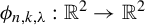 $\phi _{n,k,\unicode{x3bb} }: \mathbb {R}^2 \to \mathbb {R}^2$
be the composition of
$\phi _{n,k,\unicode{x3bb} }: \mathbb {R}^2 \to \mathbb {R}^2$
be the composition of
 $\phi _{n,0,\unicode{x3bb} }$
and rotation by
$\phi _{n,0,\unicode{x3bb} }$
and rotation by
 ${2\pi k}/{n}$
anticlockwise. Since
${2\pi k}/{n}$
anticlockwise. Since
 $[\begin {smallmatrix} \unicode{x3bb} & 0\\ 0 & \unicode{x3bb} ^{-1} \end {smallmatrix}]$
preserves the foliations of
$[\begin {smallmatrix} \unicode{x3bb} & 0\\ 0 & \unicode{x3bb} ^{-1} \end {smallmatrix}]$
preserves the foliations of
 $\mathbb {R}^2$
by vertical and horizontal lines, respectively,
$\mathbb {R}^2$
by vertical and horizontal lines, respectively,
 $l_n^s$
and
$l_n^s$
and
 $l_n^u$
are preserved by
$l_n^u$
are preserved by
 $\phi _{n,k,\unicode{x3bb} }$
. We depict the dynamics of
$\phi _{n,k,\unicode{x3bb} }$
. We depict the dynamics of
 $\phi _{n,0,\unicode{x3bb} }$
for
$\phi _{n,0,\unicode{x3bb} }$
for
 $n=3$
in Figure 1.
$n=3$
in Figure 1.
The dynamics of
 $\phi _{n,0,\unicode{x3bb} }$
for
$\phi _{n,0,\unicode{x3bb} }$
for
 $n=3$
.
$n=3$
.

Let
 $\Phi _{n,k,\unicode{x3bb} }$
be the mapping torus of
$\Phi _{n,k,\unicode{x3bb} }$
be the mapping torus of
 $\phi _{n,k, \unicode{x3bb} }$
, let
$\phi _{n,k, \unicode{x3bb} }$
, let
 $\Lambda ^s, \Lambda ^u$
be the suspensions of
$\Lambda ^s, \Lambda ^u$
be the suspensions of
 $l^s_n, l^u_n$
, respectively, and consider the suspension flow on
$l^s_n, l^u_n$
, respectively, and consider the suspension flow on
 $\Phi _{n,k, \unicode{x3bb} }$
. Call the suspension of the origin the singular orbit of
$\Phi _{n,k, \unicode{x3bb} }$
. Call the suspension of the origin the singular orbit of
 $\Phi _{n,k,\unicode{x3bb} }$
.
$\Phi _{n,k,\unicode{x3bb} }$
.
Definition 2.2. A pseudo-Anosov flow on a closed 3-manifold M is a
 $C^1$
-flow
$C^1$
-flow
 $\phi _t$
satisfying the following.
$\phi _t$
satisfying the following.
-
• There is a finite collection of closed orbits
$\{\gamma _1, \ldots , \gamma _s \}$
, called the singular orbits, such that
$\phi _t$
is smooth away from the singular orbits. -
• There is a path metric d on M, which is induced from a Riemannian metric g away from the singular orbits.
-
• Away from the singular orbits, there is a splitting of the tangent bundle into three
$\phi _t$
-invariant line bundles
$TM=E^s \oplus E^u \oplus T\phi _t$
, such that for every
$$ \begin{align*}|d\phi_t(v)| < C \unicode{x3bb}^{-t} |v|\end{align*} $$
$v \in E^s, t>0$
, and for every
$$ \begin{align*}|d\phi_t(v)| < C \unicode{x3bb}^t |v|\end{align*} $$
$v \in E^u, t<0$
, for some
$C, \unicode{x3bb}>1$
.
-
• Each singular orbit
$\gamma _i$
has a neighborhood
$N_i$
and a map
$f_i$
sending
$N_i$
to a neighborhood of the singular orbit in
$\Phi _{n_i, k_i, \unicode{x3bb} }$
, for some
$n_i \geq 3$
, such that
$f_i$
is bi-Lipschitz on
$N_i$
and smooth away from
$\gamma _i$
, preserves the orbits, and sends
$E^s, E^u$
to line bundles tangent to
$\Lambda ^s, \Lambda ^u$
, respectively. In this case, we say that
$\gamma _i$
is
$n_i$
-pronged. By extension, we also say that a non-singular orbit is
$2$
-pronged.


We call the (possibly singular) foliation which is tangent to
 $E^s \oplus T\phi _t$
away from the singular orbits and given by the image of
$E^s \oplus T\phi _t$
away from the singular orbits and given by the image of
 $\Lambda ^s \subset \Phi _{n_i,k_i,\unicode{x3bb} }$
under
$\Lambda ^s \subset \Phi _{n_i,k_i,\unicode{x3bb} }$
under
 $f_i$
near the singular orbits the stable foliation
$f_i$
near the singular orbits the stable foliation
 $\Lambda ^s$
. We define the unstable foliation
$\Lambda ^s$
. We define the unstable foliation
 $\Lambda ^u$
similarly.
$\Lambda ^u$
similarly.
An Anosov flow is a pseudo-Anosov flow without singular orbits.
Definition 2.3. A flow on a closed 3-manifold M is said to be transitive if it has an orbit that is dense in M.
Definition 2.4. Let
 $\phi _i$
be a flow on a 3-manifold
$\phi _i$
be a flow on a 3-manifold
 $M_i$
for
$M_i$
for
 $i=1,2$
. We say that
$i=1,2$
. We say that
 $\phi _1$
is orbit equivalent to
$\phi _1$
is orbit equivalent to
 $\phi _2$
if there is a homeomorphism
$\phi _2$
if there is a homeomorphism
 $h:M_1 \to M_2$
sending orbits of
$h:M_1 \to M_2$
sending orbits of
 $\phi _1$
to orbits of
$\phi _1$
to orbits of
 $\phi _2$
in an orientation preserving way (but not necessarily preserving the parameterizations by the flows). In this case, we say that h is an orbit equivalence.
$\phi _2$
in an orientation preserving way (but not necessarily preserving the parameterizations by the flows). In this case, we say that h is an orbit equivalence.
We next recall the definition of no perfect fits. This was introduced by Fenley in [Reference FenleyFen99] and slightly generalized in [Reference Agol and TsangAT22]. Here we use the generalized definition.
Definition 2.5. Let
 $\phi $
be a pseudo-Anosov flow on a closed 3-manifold M, and let
$\phi $
be a pseudo-Anosov flow on a closed 3-manifold M, and let
 $\mathcal {C}$
be a non-empty finite collection of closed orbits of
$\mathcal {C}$
be a non-empty finite collection of closed orbits of
 $\phi $
which includes all the singular orbits of
$\phi $
which includes all the singular orbits of
 $\phi $
. Lift
$\phi $
. Lift
 $\phi $
up to a flow
$\phi $
up to a flow
 $\widetilde {\phi }$
on the universal cover
$\widetilde {\phi }$
on the universal cover
 $\widetilde {M}$
. Let
$\widetilde {M}$
. Let
 $\widetilde {\mathcal {C}}$
be the set of orbits of
$\widetilde {\mathcal {C}}$
be the set of orbits of
 $\widetilde {\phi }$
which cover the orbits in
$\widetilde {\phi }$
which cover the orbits in
 $\mathcal {C}$
.
$\mathcal {C}$
.
Let
 $\mathcal {O}$
be the space of orbits of
$\mathcal {O}$
be the space of orbits of
 $\widetilde {\phi }$
, endowed with the quotient topology. We refer to
$\widetilde {\phi }$
, endowed with the quotient topology. We refer to
 $\mathcal {O}$
as the orbit space of
$\mathcal {O}$
as the orbit space of
 $\phi $
. It is shown in [Reference Fenley and MosherFM01, Proposition 4.2] that
$\phi $
. It is shown in [Reference Fenley and MosherFM01, Proposition 4.2] that
 $\mathcal {O}$
is homeomorphic to
$\mathcal {O}$
is homeomorphic to
 $\mathbb {R}^2$
, and the images of
$\mathbb {R}^2$
, and the images of
 $\Lambda ^s, \Lambda ^u$
under the projection
$\Lambda ^s, \Lambda ^u$
under the projection
 $\widetilde {M} \to \mathcal {O}$
are two (possibly singular) one-dimensional foliations
$\widetilde {M} \to \mathcal {O}$
are two (possibly singular) one-dimensional foliations
 $\mathcal {O}^s, \mathcal {O}^u$
, respectively.
$\mathcal {O}^s, \mathcal {O}^u$
, respectively.
A perfect fit rectangle is a rectangle-with-one-ideal-vertex properly embedded in
 $\mathcal {O}$
such that the restrictions of
$\mathcal {O}$
such that the restrictions of
 $\mathcal {O}^s$
and
$\mathcal {O}^s$
and
 $\mathcal {O}^u$
to the rectangle foliate it as a product that is conjugate to the foliations of
$\mathcal {O}^u$
to the rectangle foliate it as a product that is conjugate to the foliations of
 $[0,1]^2 \backslash \{(1,1)\}$
by vertical and horizontal lines. See Figure 2.
$[0,1]^2 \backslash \{(1,1)\}$
by vertical and horizontal lines. See Figure 2.
A perfect fit rectangle.

We say that
 $\phi $
has no perfect fits relative to
$\phi $
has no perfect fits relative to
 $\mathcal {C}$
if every perfect fit rectangle in
$\mathcal {C}$
if every perfect fit rectangle in
 $\mathcal {O}$
intersects
$\mathcal {O}$
intersects
 $\widetilde {\mathcal {C}}$
.
$\widetilde {\mathcal {C}}$
.
If
 $\phi $
has no perfect fits relative to the collection of singular orbits, then we say that
$\phi $
has no perfect fits relative to the collection of singular orbits, then we say that
 $\phi $
has no perfect fits.
$\phi $
has no perfect fits.
Construction 2.6. Let
 $\phi $
be a pseudo-Anosov flow on a closed 3-manifold M and let
$\phi $
be a pseudo-Anosov flow on a closed 3-manifold M and let
 $\gamma $
be a closed orbit of
$\gamma $
be a closed orbit of
 $\phi $
. Let
$\phi $
. Let
 $N(\gamma )$
be a small tubular neighborhood of
$N(\gamma )$
be a small tubular neighborhood of
 $\gamma $
. The leaf of the restricted foliation
$\gamma $
. The leaf of the restricted foliation
 $\Lambda ^s|_{N(\gamma )}$
containing
$\Lambda ^s|_{N(\gamma )}$
containing
 $\gamma $
intersects
$\gamma $
intersects
 $\partial N(\gamma )$
in a collection of closed curves. Let l be the union of all these curves.
$\partial N(\gamma )$
in a collection of closed curves. Let l be the union of all these curves.
Let s be a slope on
 $\partial N(\gamma )$
such that
$\partial N(\gamma )$
such that
 $|\langle s,l \rangle | \geq 2$
, and let
$|\langle s,l \rangle | \geq 2$
, and let
 $M'$
be the closed 3-manifold obtained by Dehn filling
$M'$
be the closed 3-manifold obtained by Dehn filling
 $M \backslash N(\gamma )$
along s. Then there exists a pseudo-Anosov flow
$M \backslash N(\gamma )$
along s. Then there exists a pseudo-Anosov flow
 $\phi '$
on
$\phi '$
on
 $M'$
with a closed orbit
$M'$
with a closed orbit
 $\gamma '$
isotopic to the core of the Dehn filling, such that
$\gamma '$
isotopic to the core of the Dehn filling, such that
 $\phi $
restricted to
$\phi $
restricted to
 $M \backslash \gamma $
is orbit equivalent to
$M \backslash \gamma $
is orbit equivalent to
 $\phi '$
restricted to
$\phi '$
restricted to
 $M' \backslash \gamma '$
. Moreover,
$M' \backslash \gamma '$
. Moreover,
 $\gamma '$
will be
$\gamma '$
will be
 $|\langle s,l \rangle |$
-pronged.
$|\langle s,l \rangle |$
-pronged.
Such a construction is commonly known in the literature as Goodman–Fried surgery. The history behind this is rather interesting. Goodman, in [Reference Goodman and PalisGoo83], introduced a way of performing this construction: one excises a round handle neighborhood of
 $\gamma $
and inserts another round handle neighborhood which achieves the correct filling slope s to get
$\gamma $
and inserts another round handle neighborhood which achieves the correct filling slope s to get
 $\phi '$
. Fried, in [Reference FriedFri83], introduced another way of performing this construction: one ‘blows up’ the flow along
$\phi '$
. Fried, in [Reference FriedFri83], introduced another way of performing this construction: one ‘blows up’ the flow along
 $\gamma $
and collapses the torus boundary component along the filling slope s to get
$\gamma $
and collapses the torus boundary component along the filling slope s to get
 $\phi '$
. It was assumed early on that the flows produced by the two methods are orbit equivalent, but it was later realized that there was no rigorous proof of this. It was only recently shown by Shannon in his thesis [Reference ShannonSha20] that this is indeed the case when
$\phi '$
. It was assumed early on that the flows produced by the two methods are orbit equivalent, but it was later realized that there was no rigorous proof of this. It was only recently shown by Shannon in his thesis [Reference ShannonSha20] that this is indeed the case when
 $\phi $
is transitive, and even now, it is still open whether this is true when
$\phi $
is transitive, and even now, it is still open whether this is true when
 $\phi $
is not transitive. See [Reference ShannonSha20] for a more in-depth discussion. For the purposes of this paper, one can just choose their preferred way of performing the surgery when we say perform Goodman–Fried surgery.
$\phi $
is not transitive. See [Reference ShannonSha20] for a more in-depth discussion. For the purposes of this paper, one can just choose their preferred way of performing the surgery when we say perform Goodman–Fried surgery.
Proposition 2.7. Let
 $\phi $
be a transitive pseudo-Anosov flow on a closed 3-manifold M. There exists a collection of orbits
$\phi $
be a transitive pseudo-Anosov flow on a closed 3-manifold M. There exists a collection of orbits
 $\mathcal {C}$
such that
$\mathcal {C}$
such that
 $\phi $
is without perfect fits relative to
$\phi $
is without perfect fits relative to
 $\mathcal {C}$
. In fact,
$\mathcal {C}$
. In fact,
 $\mathcal {C}$
can be chosen to be the set of singular orbits and one other orbit.
$\mathcal {C}$
can be chosen to be the set of singular orbits and one other orbit.
Proof. We first make the following definition.
Definition 2.8. Recall the notation in Definition 2.1. The preimage of the square
 $[-1,1]^2$
under
$[-1,1]^2$
under
 $p_n$
is a
$p_n$
is a
 $2n$
-gon. We call the copy of this
$2n$
-gon. We call the copy of this
 $2n$
-gon in a fiber of the mapping torus
$2n$
-gon in a fiber of the mapping torus
 $\Phi _{n,k,\unicode{x3bb} }$
a standard transverse
$\Phi _{n,k,\unicode{x3bb} }$
a standard transverse
 $2n$
-gon.
$2n$
-gon.
Now suppose
 $x \in M$
. Suppose f is a homeomorphism sending a neighborhood of x to a neighborhood in
$x \in M$
. Suppose f is a homeomorphism sending a neighborhood of x to a neighborhood in
 $\Phi _{n,k,\unicode{x3bb} }$
containing a standard transverse
$\Phi _{n,k,\unicode{x3bb} }$
containing a standard transverse
 $2n$
-gon R such that:
$2n$
-gon R such that:
-
• f preserves the foliations
$\Lambda ^s$
and
$\Lambda ^u$
; -
• f sends x to a point
$y \in R$
.


Then we call the preimage
 $f^{-1}(R)$
a transverse polygon at x. The leaves of
$f^{-1}(R)$
a transverse polygon at x. The leaves of
 $l^s_n$
and
$l^s_n$
and
 $l^u_n$
that contain y divide R into certain regions. We call the preimage of one of these regions that contains y a sector of the transverse polygon.
$l^u_n$
that contain y divide R into certain regions. We call the preimage of one of these regions that contains y a sector of the transverse polygon.
Notice that we do not require x or y to lie on a singular orbit in this definition. Hence, for example, a transverse polygon at a point lying on a non-singular orbit can be a
 $(2n \geq 6)$
-gon, but in such a case, the transverse polygon will still only have four sectors.
$(2n \geq 6)$
-gon, but in such a case, the transverse polygon will still only have four sectors.
Returning to the proof of the proposition, we fix some metric on M. There exists
 $\epsilon> 0$
such that for every
$\epsilon> 0$
such that for every
 $x \in M$
, there is a transverse polygon R at x for which each sector S of R intersects every orbit passing through the
$x \in M$
, there is a transverse polygon R at x for which each sector S of R intersects every orbit passing through the
 $\epsilon $
-neighborhood of some point
$\epsilon $
-neighborhood of some point
 $z \in S$
. Such
$z \in S$
. Such
 $\epsilon $
can be chosen for x in small neighborhoods, then using compactness of M, we obtain a uniform
$\epsilon $
can be chosen for x in small neighborhoods, then using compactness of M, we obtain a uniform
 $\epsilon $
.
$\epsilon $
.
Meanwhile, by transitivity and the shadowing lemma (see [Reference MangumMan98, Lemma 1.3]), there exists a closed orbit
 $\gamma $
of
$\gamma $
of
 $\phi $
that intersects every
$\phi $
that intersects every
 $\epsilon $
-neighborhood in M. By the choice of
$\epsilon $
-neighborhood in M. By the choice of
 $\epsilon $
above, we know that for every
$\epsilon $
above, we know that for every
 $x \in M$
, there is a transverse polygon R at x such that
$x \in M$
, there is a transverse polygon R at x such that
 $\gamma $
intersects every sector of R. We take
$\gamma $
intersects every sector of R. We take
 $\mathcal {C}$
to be the set of singular orbits and
$\mathcal {C}$
to be the set of singular orbits and
 $\gamma $
, and claim that
$\gamma $
, and claim that
 $\phi $
has no perfect fits relative to
$\phi $
has no perfect fits relative to
 $\mathcal {C}$
.
$\mathcal {C}$
.
To show the claim, we recall the notion of lozenges, which were also introduced by Fenley in [Reference FenleyFen99].
Definition 2.9. A lozenge is a rectangle-with-two-opposite-ideal-vertices properly embedded in
 $\mathcal {O}$
such that the restrictions of
$\mathcal {O}$
such that the restrictions of
 $\mathcal {O}^s$
and
$\mathcal {O}^s$
and
 $\mathcal {O}^u$
to the rectangle foliate it as a product that is conjugate to the foliations of
$\mathcal {O}^u$
to the rectangle foliate it as a product that is conjugate to the foliations of
 $[0,1]^2 \backslash \{(0,0), (1,1)\}$
by vertical and horizontal lines. See Figure 3.
$[0,1]^2 \backslash \{(0,0), (1,1)\}$
by vertical and horizontal lines. See Figure 3.
A lozenge.

The result we need to use is the following.
Proposition 2.10. [Reference FenleyFen16, Proposition 5.5]
Let
 $\phi $
be a pseudo-Anosov flow on a closed 3-manifold M. If the orbit space of
$\phi $
be a pseudo-Anosov flow on a closed 3-manifold M. If the orbit space of
 $\phi $
contains a perfect fit rectangle, then it contains a lozenge.
$\phi $
contains a perfect fit rectangle, then it contains a lozenge.
Returning to the proof of our claim, we first perform Goodman–Fried surgery on
 $\mathcal {\gamma }$
to make it singular, that is, we get a pseudo-Anosov flow
$\mathcal {\gamma }$
to make it singular, that is, we get a pseudo-Anosov flow
 $\phi '$
on a closed 3-manifold
$\phi '$
on a closed 3-manifold
 $M'$
with a singular orbit
$M'$
with a singular orbit
 $\gamma '$
, such that
$\gamma '$
, such that
 $\phi $
restricted to
$\phi $
restricted to
 $M \backslash \gamma $
is orbit equivalent to
$M \backslash \gamma $
is orbit equivalent to
 $\phi '$
restricted to
$\phi '$
restricted to
 $M' \backslash \gamma '$
. If we let
$M' \backslash \gamma '$
. If we let
 $\mathcal {O}$
and
$\mathcal {O}$
and
 $\mathcal {O}'$
be the orbit spaces of
$\mathcal {O}'$
be the orbit spaces of
 $\phi $
and
$\phi $
and
 $\phi '$
, respectively, then the orbit equivalence
$\phi '$
, respectively, then the orbit equivalence
 $M \backslash \gamma \cong M' \backslash \gamma '$
induces a homeomorphism
$M \backslash \gamma \cong M' \backslash \gamma '$
induces a homeomorphism
 $\widetilde {\mathcal {O} \backslash \widetilde {\{\gamma \}}} \cong \widetilde {\mathcal {O}' \backslash \widetilde {\{\gamma '\}}}$
which maps the lifted stable/unstable foliations of one flow to the other.
$\widetilde {\mathcal {O} \backslash \widetilde {\{\gamma \}}} \cong \widetilde {\mathcal {O}' \backslash \widetilde {\{\gamma '\}}}$
which maps the lifted stable/unstable foliations of one flow to the other.
Now suppose that
 $\mathcal {O}$
contains a perfect fit rectangle disjoint from
$\mathcal {O}$
contains a perfect fit rectangle disjoint from
 $\widetilde {\{\gamma \}}$
, then we can lift it to
$\widetilde {\{\gamma \}}$
, then we can lift it to
 $\widetilde {\mathcal {O} \backslash \widetilde {\{\gamma \}}}$
, transfer it to
$\widetilde {\mathcal {O} \backslash \widetilde {\{\gamma \}}}$
, transfer it to
 $\widetilde {\mathcal {O}' \backslash \widetilde {\{\gamma '\}}}$
, then project down to
$\widetilde {\mathcal {O}' \backslash \widetilde {\{\gamma '\}}}$
, then project down to
 $\mathcal {O}'$
to get a perfect fit rectangle in
$\mathcal {O}'$
to get a perfect fit rectangle in
 $\mathcal {O}'$
. By Proposition 2.10,
$\mathcal {O}'$
. By Proposition 2.10,
 $\mathcal {O}'$
contains a lozenge. We can then run the above reasoning backward to obtain a lozenge L in
$\mathcal {O}'$
contains a lozenge. We can then run the above reasoning backward to obtain a lozenge L in
 $\mathcal {O}$
disjoint from
$\mathcal {O}$
disjoint from
 $\widetilde {\{\gamma \}}$
.
$\widetilde {\{\gamma \}}$
.
Let
 $\alpha $
be one of the (non-ideal) corners of L. Recall that
$\alpha $
be one of the (non-ideal) corners of L. Recall that
 $\alpha $
is an orbit of
$\alpha $
is an orbit of
 $\widetilde {\phi }$
. Let x be a point on
$\widetilde {\phi }$
. Let x be a point on
 $\alpha $
. We know from above that there is a transverse polygon R at the image of x in M such that
$\alpha $
. We know from above that there is a transverse polygon R at the image of x in M such that
 $\gamma $
intersects every sector of R. Lift R to
$\gamma $
intersects every sector of R. Lift R to
 $\widetilde {R} \subset \widetilde {M}$
containing x. One of the sectors of
$\widetilde {R} \subset \widetilde {M}$
containing x. One of the sectors of
 $\widetilde {R}$
projects down to a region contained in
$\widetilde {R}$
projects down to a region contained in
 $L \subset \mathcal {O}$
. However, some element of
$L \subset \mathcal {O}$
. However, some element of
 $\widetilde {\{\gamma \}}$
lies within such a region, contradicting the fact that L is disjoint from
$\widetilde {\{\gamma \}}$
lies within such a region, contradicting the fact that L is disjoint from
 $\widetilde {\{\gamma \}}$
.
$\widetilde {\{\gamma \}}$
.
Remark 2.11. We note that, conversely, if
 $\phi $
is a pseudo-Anosov flow on a closed 3-manifold M without perfect fits relative to some collection of closed orbits
$\phi $
is a pseudo-Anosov flow on a closed 3-manifold M without perfect fits relative to some collection of closed orbits
 $\mathcal {C}$
, then
$\mathcal {C}$
, then
 $\phi $
must be transitive.
$\phi $
must be transitive.
To show this, we first perform Goodman–Fried surgery on orbits in
 $\mathcal {C}$
to make them singular, that is, we get a pseudo-Anosov flow
$\mathcal {C}$
to make them singular, that is, we get a pseudo-Anosov flow
 $\phi '$
on a closed 3-manifold
$\phi '$
on a closed 3-manifold
 $M'$
with a collection of singular orbits
$M'$
with a collection of singular orbits
 $\mathcal {C'}$
, such that
$\mathcal {C'}$
, such that
 $\phi $
restricted to
$\phi $
restricted to
 $M \backslash \bigcup \mathcal {C}$
is orbit equivalent to
$M \backslash \bigcup \mathcal {C}$
is orbit equivalent to
 $\phi '$
restricted to
$\phi '$
restricted to
 $M' \backslash \bigcup \mathcal {C'}$
.
$M' \backslash \bigcup \mathcal {C'}$
.
We claim that
 $\phi '$
has no perfect fits. Otherwise, using the argument in the proof above, we can transfer a perfect fit rectangle in
$\phi '$
has no perfect fits. Otherwise, using the argument in the proof above, we can transfer a perfect fit rectangle in
 $\mathcal {O}'$
to a perfect fit rectangle in
$\mathcal {O}'$
to a perfect fit rectangle in
 $\mathcal {O}$
that is disjoint from
$\mathcal {O}$
that is disjoint from
 $\widetilde {\mathcal {C}}$
, contradicting the hypothesis. Now by [Reference FenleyFen12, Corollary E],
$\widetilde {\mathcal {C}}$
, contradicting the hypothesis. Now by [Reference FenleyFen12, Corollary E],
 $M'$
is atoroidal, and by [Reference MosherMos92, Proposition 2.7],
$M'$
is atoroidal, and by [Reference MosherMos92, Proposition 2.7],
 $\phi '$
is transitive. This implies that
$\phi '$
is transitive. This implies that
 $\phi $
is transitive.
$\phi $
is transitive.
Remark 2.12. Using Theorem 1.1, one can obtain a much simpler proof of the first part of Proposition 2.7. Indeed, the existence of a Birkhoff section, say, with boundary along a collection of closed orbits
 $\mathcal {C}$
, implies that there exists a pseudo-Anosov flow
$\mathcal {C}$
, implies that there exists a pseudo-Anosov flow
 $\phi '$
on a closed 3-manifold
$\phi '$
on a closed 3-manifold
 $M'$
with a collection of closed orbits
$M'$
with a collection of closed orbits
 $\mathcal {C'}$
, such that
$\mathcal {C'}$
, such that
 $\phi '$
is the suspension flow on some pseudo-Anosov mapping torus, and such that
$\phi '$
is the suspension flow on some pseudo-Anosov mapping torus, and such that
 $\phi $
restricted to
$\phi $
restricted to
 $M \backslash \bigcup \mathcal {C}$
is orbit equivalent to
$M \backslash \bigcup \mathcal {C}$
is orbit equivalent to
 $\phi '$
restricted to
$\phi '$
restricted to
 $M' \backslash \bigcup \mathcal {C'}$
.
$M' \backslash \bigcup \mathcal {C'}$
.
However, it is well known that suspension flows have no perfect fits, see, for example, [Reference FenleyFen12, Theorem G]. Hence,
 $\phi $
has no perfect fits relative to
$\phi $
has no perfect fits relative to
 $\mathcal {C}$
, for otherwise, we can apply the argument in the proof above to transfer a perfect fit rectangle in
$\mathcal {C}$
, for otherwise, we can apply the argument in the proof above to transfer a perfect fit rectangle in
 $\mathcal {O}$
disjoint from
$\mathcal {O}$
disjoint from
 $\widetilde {\mathcal {C}}$
to a perfect fit rectangle in
$\widetilde {\mathcal {C}}$
to a perfect fit rectangle in
 $\mathcal {O}'$
.
$\mathcal {O}'$
.
One of the drawbacks of this proof, however, is that, as pointed out in §1, Fried’s and Brunella’s proofs of Theorem 1.1 do not offer any control over the complexity of
 $\mathcal {C}$
. In particular, we do not know of a way of recovering the second statement of Proposition 2.7 using this proof. Another reason for using the longer proof is that we aim to offer an independent proof of Theorem 1.1 in this paper, and so we should avoid a circular argument.
$\mathcal {C}$
. In particular, we do not know of a way of recovering the second statement of Proposition 2.7 using this proof. Another reason for using the longer proof is that we aim to offer an independent proof of Theorem 1.1 in this paper, and so we should avoid a circular argument.
One of the convenient features of a pseudo-Anosov flow without perfect fits is the following generalization of [Reference FenleyFen99, Theorem 4.8].
Lemma 2.13. Let
 $\phi $
be a pseudo-Anosov flow on a closed 3-manifold M without perfect fits relative to a collection of orbits
$\phi $
be a pseudo-Anosov flow on a closed 3-manifold M without perfect fits relative to a collection of orbits
 $\mathcal {C}$
. Suppose
$\mathcal {C}$
. Suppose
 $\gamma _1$
and
$\gamma _1$
and
 $\gamma _2$
are two closed orbits of
$\gamma _2$
are two closed orbits of
 $\phi $
which are not elements of
$\phi $
which are not elements of
 $\mathcal {C}$
. If
$\mathcal {C}$
. If
 $[\gamma _1]^{k_1} = [\gamma _2]^{k_2}$
in
$[\gamma _1]^{k_1} = [\gamma _2]^{k_2}$
in
 $\pi _1(M \backslash \bigcup \mathcal {C})$
, then
$\pi _1(M \backslash \bigcup \mathcal {C})$
, then
 $\gamma _1 = \gamma _2$
.
$\gamma _1 = \gamma _2$
.
Proof. Assume otherwise. We apply Goodman–Fried surgery on the orbits in
 $\mathcal {C}$
to make them singular, that is, we get a pseudo-Anosov flow
$\mathcal {C}$
to make them singular, that is, we get a pseudo-Anosov flow
 $\phi '$
on a closed 3-manifold
$\phi '$
on a closed 3-manifold
 $M'$
with a collection of singular orbits
$M'$
with a collection of singular orbits
 $\mathcal {C'}$
, such that
$\mathcal {C'}$
, such that
 $\phi $
restricted to
$\phi $
restricted to
 $M \backslash \bigcup \mathcal {C}$
is orbit equivalent to
$M \backslash \bigcup \mathcal {C}$
is orbit equivalent to
 $\phi '$
restricted to
$\phi '$
restricted to
 $M' \backslash \bigcup \mathcal {C'}$
. Here,
$M' \backslash \bigcup \mathcal {C'}$
. Here,
 $\gamma _1$
and
$\gamma _1$
and
 $\gamma _2$
are sent by the orbit equivalence to closed orbits of
$\gamma _2$
are sent by the orbit equivalence to closed orbits of
 $\phi '$
in
$\phi '$
in
 $M' \backslash \bigcup \mathcal {C'}$
, which we still call
$M' \backslash \bigcup \mathcal {C'}$
, which we still call
 $\gamma _1$
and
$\gamma _1$
and
 $\gamma _2$
, respectively, such that
$\gamma _2$
, respectively, such that
 $\gamma _1^{k_1}$
is homotopic to
$\gamma _1^{k_1}$
is homotopic to
 $\gamma _2^{k_2}$
in
$\gamma _2^{k_2}$
in
 $M'$
. By [Reference FenleyFen99, Theorem 4.8],
$M'$
. By [Reference FenleyFen99, Theorem 4.8],
 $\phi '$
must have perfect fits. However, then one can transfer a perfect fit rectangle from the orbit space of
$\phi '$
must have perfect fits. However, then one can transfer a perfect fit rectangle from the orbit space of
 $\phi '$
to that of
$\phi '$
to that of
 $\phi $
as in the proof of Proposition 2.7 and obtain a contradiction.
$\phi $
as in the proof of Proposition 2.7 and obtain a contradiction.
2.2 Birkhoff sections
Definition 2.14. Let
 $\phi $
be a pseudo-Anosov flow on a closed 3-manifold M. An immersed Birkhoff section is an immersed cooriented compact surface with boundary S such that the following hold.
$\phi $
be a pseudo-Anosov flow on a closed 3-manifold M. An immersed Birkhoff section is an immersed cooriented compact surface with boundary S such that the following hold.
-
• The interior of S is positively transverse to the orbits of
$\phi $
. -
• The boundary of S is a union of closed orbits of
$\phi $
. -
• Every orbit of
$\phi $
intersects S in finite foward and finite backward time, that is, for every
$x \in M$
, there exists
$t_1, t_2> 0$
such that
$\phi _{t_1}(x) \in S$
and
$\phi _{-t_2}(x) \in S$
.


When M is oriented, we orient the boundary components of S using the induced orientation on S. We say that a boundary component of S is positive if its orientation agrees with the flow direction, otherwise it is negative. See Figure 4.
A Birkhoff section near a positive/negative boundary component.

Let
 $\mathcal {C}$
be the set of closed orbits for which some element of
$\mathcal {C}$
be the set of closed orbits for which some element of
 $\partial S$
lies along. The complexity of S is defined to be
$\partial S$
lies along. The complexity of S is defined to be
 $\mathfrak {c}(S) = -\chi _{{\mathrm {top}}} (S \backslash \mathcal {C})$
, where
$\mathfrak {c}(S) = -\chi _{{\mathrm {top}}} (S \backslash \mathcal {C})$
, where
 $\chi _{{\mathrm {top}}}$
denotes the Euler characteristic of the underlying space. In other words, we puncture the immersed surface at the points where it intersects its boundary and compute the negative of its Euler characteristic.
$\chi _{{\mathrm {top}}}$
denotes the Euler characteristic of the underlying space. In other words, we puncture the immersed surface at the points where it intersects its boundary and compute the negative of its Euler characteristic.
A Birkhoff section is an immersed Birkhoff section that is embedded in its interior. Note that the complexity of a Birkhoff section is equal to the negative of its Euler characteristic.
Having an immersed Birkhoff section is essentially as good as having a Birkhoff section, since we have the following resolution trick, introduced by Fried in [Reference FriedFri83].
Construction 2.15. Let
 $\phi $
be a pseudo-Anosov flow on a closed 3-manifold M. Let S be an immersed Birkhoff section. By a slight perturbation, we can assume that S is in general position. In this case, the self-intersection set of S is a graph that can be described as follows.
$\phi $
be a pseudo-Anosov flow on a closed 3-manifold M. Let S be an immersed Birkhoff section. By a slight perturbation, we can assume that S is in general position. In this case, the self-intersection set of S is a graph that can be described as follows.
We call the interior points that are identified with a boundary point the cut points, and call the interior points that are identified with two other interior points the triple points. Then the self-intersection set of S is a union of some boundary components and some curves and arcs that have endpoints on boundary components and cut points, and which are disjoint except for intersecting three at a time at triple points. We call each such a curve or arc a double curve or arc, respectively.
For each double curve or arc l, we cut and paste along l as in Figure 5 first row. The local picture around a cut point is as in Figure 5 second row, and the local picture around a triple point is as in Figure 5 third row. This results in a surface that is embedded in its interior but may not be immersed along its boundary. We call the boundary points that are not immersed the turning points. Inductively, for each turning point, we cut and paste along the arcs that are identified on either side of the turning point as in Figure 5 last row. We eventually get rid of all the turning points and get a Birkhoff section
 $S'$
. We call
$S'$
. We call
 $S'$
the Fried resolution of S.
$S'$
the Fried resolution of S.
Performing Fried resolution on an immersed Birkhoff section.

We caution that a closed orbit
 $\gamma $
in
$\gamma $
in
 $\partial S$
may not be in
$\partial S$
may not be in
 $\partial S'$
. This disappearance of boundary orbits happens exactly when the homology class of
$\partial S'$
. This disappearance of boundary orbits happens exactly when the homology class of
 $S \cap \partial N(\gamma )$
is a multiple of the meridian, where in the last step of getting rid of the turning points, we end up collapsing the boundary components that lie on
$S \cap \partial N(\gamma )$
is a multiple of the meridian, where in the last step of getting rid of the turning points, we end up collapsing the boundary components that lie on
 $\gamma $
.
$\gamma $
.
We also note that if
 $\partial S$
is embedded along a closed orbit
$\partial S$
is embedded along a closed orbit
 $\gamma $
, then the same is true for
$\gamma $
, then the same is true for
 $\partial S'$
. In general, the (signed) intersection number of
$\partial S'$
. In general, the (signed) intersection number of
 $S \cap \partial N(\gamma )$
with the meridian at
$S \cap \partial N(\gamma )$
with the meridian at
 $\gamma $
is preserved under Fried resolution, since the effect of the operation on the homology class of
$\gamma $
is preserved under Fried resolution, since the effect of the operation on the homology class of
 $S \cap \partial N(\gamma )$
is summing with multiples of the meridian.
$S \cap \partial N(\gamma )$
is summing with multiples of the meridian.
Lemma 2.16. Let S be an immersed Birkhoff section and
 $S'$
be its Fried resolution. Then
$S'$
be its Fried resolution. Then
 $\mathfrak {c}(S) \geq \mathfrak {c}(S')$
.
$\mathfrak {c}(S) \geq \mathfrak {c}(S')$
.
To explain this proof, we make the following definition.
Definition 2.17. A surface with corners is a surface with boundary S along with a finite collection of points on
 $\partial S$
, which we call the corners. The complementary regions of the corners in
$\partial S$
, which we call the corners. The complementary regions of the corners in
 $\partial S$
are called the sides. A punctured surface with corners is a surface with corners S with a finite collection of interior points and corners removed.
$\partial S$
are called the sides. A punctured surface with corners is a surface with corners S with a finite collection of interior points and corners removed.
The index of a surface with corners S is defined to be
 ${\mathrm {ind}}(S) = \chi _{{\mathrm {top}}}(S) - \tfrac 14 \text {# corners}$
. If we remove x interior points and y corners from S to get a punctured surface with corners
${\mathrm {ind}}(S) = \chi _{{\mathrm {top}}}(S) - \tfrac 14 \text {# corners}$
. If we remove x interior points and y corners from S to get a punctured surface with corners
 $S'$
, then the index of
$S'$
, then the index of
 $S'$
is defined to be
$S'$
is defined to be
 ${\mathrm {ind}}(S') = {\mathrm {ind}}(S)-x-\tfrac 14 y$
.
${\mathrm {ind}}(S') = {\mathrm {ind}}(S)-x-\tfrac 14 y$
.
Note that the index is additive, in the sense that if a punctured surface with corners S is divided into
 $S'$
by a collection of disjoint curves and properly embedded arcs, then
$S'$
by a collection of disjoint curves and properly embedded arcs, then
 ${\mathrm {ind}}(S)={\mathrm {ind}}(S')$
.
${\mathrm {ind}}(S)={\mathrm {ind}}(S')$
.
Remark 2.18. A good motivation and mnemonic for the definition of the index comes from the Gauss–Bonnet formula: if a surface with corners S can be endowed with a hyperbolic metric such that the sides are geodesic and the corners form right angles, then
 ${\mathrm {ind}}(S)=-{\text {area}(S)}/{2\pi }$
. Similarly, if a punctured surface with corners
${\mathrm {ind}}(S)=-{\text {area}(S)}/{2\pi }$
. Similarly, if a punctured surface with corners
 $S'$
is obtained by removing interior points and corners from S, and if
$S'$
is obtained by removing interior points and corners from S, and if
 $S'$
admits a hyperbolic metric such that the sides are geodesics, the unremoved corners form right angles, and the removed points form cusps, then
$S'$
admits a hyperbolic metric such that the sides are geodesics, the unremoved corners form right angles, and the removed points form cusps, then
 ${\mathrm {ind}}(S)=-{\text {area}(S)}/{2\pi }$
.
${\mathrm {ind}}(S)=-{\text {area}(S)}/{2\pi }$
.
Proof of Lemma 2.16
Let I be the self-intersection set of S and let V be the set of cut points and triple points of S. Let
 $S_1$
be the surface obtained after cutting and pasting along the double curves and arcs of S, and let
$S_1$
be the surface obtained after cutting and pasting along the double curves and arcs of S, and let
 $I_1$
and
$I_1$
and
 $V_1$
be the images of I and V in
$V_1$
be the images of I and V in
 $S_1$
, respectively. Notice that
$S_1$
, respectively. Notice that
 $S_1$
can be obtained from S by cutting along I and gluing back the pieces in a different way.
$S_1$
can be obtained from S by cutting along I and gluing back the pieces in a different way.
Now observe that
 $I \backslash V$
is a collection of curves and properly embedded arcs in the punctured surface
$I \backslash V$
is a collection of curves and properly embedded arcs in the punctured surface
 $S \backslash V$
that divides it into punctured surface with corners
$S \backslash V$
that divides it into punctured surface with corners
 $(S \backslash V) {\backslash \!\backslash } (I \backslash V)$
. Similarly,
$(S \backslash V) {\backslash \!\backslash } (I \backslash V)$
. Similarly,
 $I_1 \backslash V_1$
is a collection of curves and properly embedded arcs in the punctured surface
$I_1 \backslash V_1$
is a collection of curves and properly embedded arcs in the punctured surface
 $S_1 \backslash V_1$
that divides it into a punctured surface with corners
$S_1 \backslash V_1$
that divides it into a punctured surface with corners
 $(S_1 \backslash V_1) {\backslash \!\backslash } (I_1 \backslash V_1)$
, and we have
$(S_1 \backslash V_1) {\backslash \!\backslash } (I_1 \backslash V_1)$
, and we have
 $(S \backslash V) {\backslash \!\backslash } (I \backslash V)=(S_1 \backslash V_1) {\backslash \!\backslash } (I_1 \backslash V_1)$
. Hence,
$(S \backslash V) {\backslash \!\backslash } (I \backslash V)=(S_1 \backslash V_1) {\backslash \!\backslash } (I_1 \backslash V_1)$
. Hence,
 ${\mathrm {ind}}(S \backslash V)={\mathrm {ind}}(S_1 \backslash V_1)$
and
${\mathrm {ind}}(S \backslash V)={\mathrm {ind}}(S_1 \backslash V_1)$
and
 $$ \begin{align*} \mathfrak{c}(S)=-{\mathrm{ind}}(S \backslash V)-\text{# triple points} = -{\mathrm{ind}}(S_1 \backslash V_1)-\text{# triple points}=-\chi_{{\mathrm{top}}}(S_1). \end{align*} $$
Meanwhile,
 $S'$
is obtained from
$S'$
is obtained from
 $S_1$
by resolving the turning points on
$S_1$
by resolving the turning points on
 $\partial S_1$
. This changes the topology of
$\partial S_1$
. This changes the topology of
 $S_1$
by possibly collapsing some boundary components. This collapsing happens when a boundary component of
$S_1$
by possibly collapsing some boundary components. This collapsing happens when a boundary component of
 $S_1$
is immersed along a closed orbit via a null-homotopic map; after resolving turning points on this boundary component, it is mapped to a single point in M. Topologically, this is equivalent to filling in certain boundary components of
$S_1$
is immersed along a closed orbit via a null-homotopic map; after resolving turning points on this boundary component, it is mapped to a single point in M. Topologically, this is equivalent to filling in certain boundary components of
 $S_1$
by discs, and hence
$S_1$
by discs, and hence
 $$ \begin{align*}\mathfrak{c}(S)=-\chi_{{\mathrm{top}}}(S_1) \geq -\chi_{{\mathrm{top}}}(S') = \mathfrak{c}(S').\\[-34pt]\end{align*} $$
As mentioned in §1, the way we will construct Birkhoff sections in this paper is to assemble multiple pieces of surfaces. To that end, we define the notion of broken transverse surfaces.
Definition 2.19. Let
 $\phi $
be a pseudo-Anosov flow on a closed 3-manifold M. A broken transverse surface is an immersed cooriented surface with corners S such that the following hold.
$\phi $
be a pseudo-Anosov flow on a closed 3-manifold M. A broken transverse surface is an immersed cooriented surface with corners S such that the following hold.
-
• The interior of S is positively transverse to the orbits of
$\phi $
. -
• Every boundary component
$\alpha $
of S has an even number of corners. The sides along
$\alpha $
lie along closed orbits or are transverse to the orbits of
$\phi $
alternatingly.


We denote the union of sides of S that lie along closed orbits by
 $\partial _v S$
and call it the vertical boundary of S. We denote the union of sides of S that are transverse to orbits of
$\partial _v S$
and call it the vertical boundary of S. We denote the union of sides of S that are transverse to orbits of
 $\phi $
by
$\phi $
by
 $\partial _h S$
and call it the horizontal boundary of S.
$\partial _h S$
and call it the horizontal boundary of S.
When M is oriented, we orient the sides of S using the induced orientation on S. A side in
 $\partial _v S$
is said to be positive if its orientation agrees with the flow direction, otherwise it is negative.
$\partial _v S$
is said to be positive if its orientation agrees with the flow direction, otherwise it is negative.
If S is a broken transverse surface whose sides in
 $\partial _h S$
can be grouped together in pairs
$\partial _h S$
can be grouped together in pairs
 $(e_1,e_2)$
such that
$(e_1,e_2)$
such that
 $e_1=-e_2$
as paths, and if every orbit of
$e_1=-e_2$
as paths, and if every orbit of
 $\phi $
intersects S in finite forward and backward time, then S can be glued along each pair of sides to give a surface immersed in its interior. The surface may not be immersed along its boundary if the signs of the sides in
$\phi $
intersects S in finite forward and backward time, then S can be glued along each pair of sides to give a surface immersed in its interior. The surface may not be immersed along its boundary if the signs of the sides in
 $\partial _v S$
do not match up, but we can apply the last step of Fried resolution to resolve any turning points and get an immersed Birkhoff section
$\partial _v S$
do not match up, but we can apply the last step of Fried resolution to resolve any turning points and get an immersed Birkhoff section
 $S'$
.
$S'$
.
Let
 $\{ \gamma _1,\ldots ,\gamma _k \}$
be the set of orbits for which some element of
$\{ \gamma _1,\ldots ,\gamma _k \}$
be the set of orbits for which some element of
 $\partial S'$
lies along. Using additivity of the index, we get the bound
$\partial S'$
lies along. Using additivity of the index, we get the bound
 $\mathfrak {c}(S') \leq - {\mathrm {ind}}(S) + \sum _{i=1}^k \langle S, \gamma _i \rangle $
. As in Lemma 2.16, strict inequality holds if we have to collapse a boundary component while resolving turning points.
$\mathfrak {c}(S') \leq - {\mathrm {ind}}(S) + \sum _{i=1}^k \langle S, \gamma _i \rangle $
. As in Lemma 2.16, strict inequality holds if we have to collapse a boundary component while resolving turning points.
2.3 Veering triangulations
We recall the definition of a veering triangulation.
Definition 2.20. An ideal tetrahedron is a tetrahedron with its four vertices removed. The removed vertices are called the ideal vertices. An ideal triangulation of a 3-manifold M is a decomposition of M into ideal tetrahedra glued along pairs of faces.
A taut structure on an ideal triangulation is a labeling of the dihedral angles by
 $0$
or
$0$
or
 $\pi $
, such that the following hold.
$\pi $
, such that the following hold.
-
• Each tetrahedron has exactly two dihedral angles labeled
$\pi $
, and they are opposite to each other. -
• The angle sum around each edge in the triangulation is
$2\pi $
.


A transverse taut structure is a taut structure along with a coorientation on each face, such that for any 0-labeled edge in a tetrahedron, exactly one of the faces adjacent to it is cooriented inwards. A transverse taut ideal triangulation is an ideal triangulation with a transverse taut structure.
In this paper, we will take the convention that the coorientations are always pointing upward.
Definition 2.21. A veering structure on a transverse taut ideal triangulation of an oriented 3-manifold is a coloring of the edges by red or blue, so that if we look at each tetrahedron with a
 $\pi $
-labeled edge in front, the four outer
$\pi $
-labeled edge in front, the four outer
 $0$
-labeled edges, starting from an end of the front edge and going counter-clockwise, are colored red, blue, red, blue, respectively. See Figure 6.
$0$
-labeled edges, starting from an end of the front edge and going counter-clockwise, are colored red, blue, red, blue, respectively. See Figure 6.
A tetrahedron in a veering triangulation. There are no restrictions on the colors of the top and bottom edges.

A veering triangulation is a transverse taut ideal triangulation with a veering structure.
Remark 2.22. In this paper, as the reader would have noticed in §2.1, we take the convention of drawing stable foliations in red and unstable foliations in blue, which is common in the literature. The reader is cautioned that this usage of red/blue has no relation with using the same colors for the edges of veering triangulations; it is simply an unfortunate coincidence, perhaps due to the fact that there are only so many conspicuous colors to the human eye. To avoid confusion, we will reserve the colors red/blue in our figures for the latter usage when both contexts are present.
We recall some basic combinatorial facts about veering triangulations.
An edge e in a veering triangulation
 $\Delta $
is the bottom edge of a unique tetrahedron and the top edge of a unique tetrahedron. We say that these tetrahedra lie above and below e, respectively. In between these tetrahedra, on either side of e, there is an (a priori, possibly empty) collection of tetrehedra incident to e, each having e as a side edge. We refer to this collection as a stack of tetrahedra on a side of e. Definition 2.23 and Proposition 2.24 below describe the structure of these stacks.
$\Delta $
is the bottom edge of a unique tetrahedron and the top edge of a unique tetrahedron. We say that these tetrahedra lie above and below e, respectively. In between these tetrahedra, on either side of e, there is an (a priori, possibly empty) collection of tetrehedra incident to e, each having e as a side edge. We refer to this collection as a stack of tetrahedra on a side of e. Definition 2.23 and Proposition 2.24 below describe the structure of these stacks.
Definition 2.23. A tetrahedron in
 $\Delta $
is called a toggle tetrahedron if the colors on its top and bottom edges differ. It is called a red/blue fan tetrahedron if both its top and bottom edges are red/blue, respectively.
$\Delta $
is called a toggle tetrahedron if the colors on its top and bottom edges differ. It is called a red/blue fan tetrahedron if both its top and bottom edges are red/blue, respectively.
Note that some authors call toggle and fan tetrahedra hinge and non-hinge, respectively.
Proposition 2.24. [Reference Futer and GuéritaudFG13, Observation 2.6]
Let e be an edge in a veering triangulation
 $\Delta $
. The stacks of tetrahedra on each side of e must be non-empty. Suppose e is blue/red. If there is exactly one tetrahedron in one stack, then that tetrahedron is a blue/red fan tetrahedron, respectively. If there are
$\Delta $
. The stacks of tetrahedra on each side of e must be non-empty. Suppose e is blue/red. If there is exactly one tetrahedron in one stack, then that tetrahedron is a blue/red fan tetrahedron, respectively. If there are
 $n>1$
tetrahedron in one stack, then going from bottom to top in that stack, the tetrahedra are: one toggle tetrahedron,
$n>1$
tetrahedron in one stack, then going from bottom to top in that stack, the tetrahedra are: one toggle tetrahedron,
 $n-2$
red/blue fan tetrahedra, and one toggle tetrahedron.
$n-2$
red/blue fan tetrahedra, and one toggle tetrahedron.
The number of tetrahedra in the stack of tetrahedra to a side of an edge is referred to as the length of the stack.
For any veering triangulation
 $\Delta $
, one can complete the ideal triangulation by adding in the removed vertices of the ideal tetrahedra. The resulting space will not be a manifold since the link of each vertex is never a ball. Regardless, we will denote this completed triangulation as
$\Delta $
, one can complete the ideal triangulation by adding in the removed vertices of the ideal tetrahedra. The resulting space will not be a manifold since the link of each vertex is never a ball. Regardless, we will denote this completed triangulation as
 $\overline {\Delta }$
. Let T be a vertex of
$\overline {\Delta }$
. Let T be a vertex of
 $\overline {\Delta }$
and let
$\overline {\Delta }$
and let
 $N(T)$
be a small neighborhood of T in
$N(T)$
be a small neighborhood of T in
 $\overline {\Delta }$
. Here,
$\overline {\Delta }$
. Here,
 $\partial N(T)$
inherits a boundary triangulation
$\partial N(T)$
inherits a boundary triangulation
 $\partial \Delta $
, where the vertices/edges/faces of
$\partial \Delta $
, where the vertices/edges/faces of
 $\partial \Delta $
correspond to vertices of edges/faces/tetrahedra of
$\partial \Delta $
correspond to vertices of edges/faces/tetrahedra of
 $\overline {\Delta }$
at T, respectively. In particular, each vertex of
$\overline {\Delta }$
at T, respectively. In particular, each vertex of
 $\partial \Delta $
inherits the color of the corresponding edge of
$\partial \Delta $
inherits the color of the corresponding edge of
 $\Delta $
, and each edge of
$\Delta $
, and each edge of
 $\partial \Delta $
inherits the coorientation of the corresponding face of
$\partial \Delta $
inherits the coorientation of the corresponding face of
 $\Delta $
.
$\Delta $
.
As a consequence of the veering structure, the boundary triangulation has to take on a particular form. Namely, there exist edge paths
 $\{l_i\}_{i \in \mathbb {Z}}$
in
$\{l_i\}_{i \in \mathbb {Z}}$
in
 $\partial \Delta $
such that the following hold.
$\partial \Delta $
such that the following hold.
-
• The vertices along
$l_{2i}$
are all colored blue, while the vertices along
$l_{2i+1}$
are all colored red. -
• The faces between
$l_{2i}$
and
$l_{2i+1}$
form a stack of upward pointing triangles, while the faces between
$l_{2i}$
and
$l_{2i+1}$
form a stack of downward pointing triangles.


See Figure 7, and see [Reference Futer and GuéritaudFG13, §2] for explanations. In this paper, we will take the convention that the indices are increasing from left to right, when we look at
 $\partial \Delta $
from inside
$\partial \Delta $
from inside
 $N(T)$
.
$N(T)$
.
The boundary triangulation at a vertex of a veering triangulation.

We orient each
 $l_i$
to go upward, that is, in the direction that agrees with the coorientations on the edges of
$l_i$
to go upward, that is, in the direction that agrees with the coorientations on the edges of
 $\partial \Delta $
. We call these oriented curves the ladderpole curves at T. If we want to be more specific, we will call
$\partial \Delta $
. We call these oriented curves the ladderpole curves at T. If we want to be more specific, we will call
 $l_i$
a blue/red ladderpole curve if it contains only blue/red vertices, respectively.
$l_i$
a blue/red ladderpole curve if it contains only blue/red vertices, respectively.
When
 $\overline {\Delta }$
is compact,
$\overline {\Delta }$
is compact,
 $\partial \Delta $
is a triangulation of the torus
$\partial \Delta $
is a triangulation of the torus
 $\partial N(T)$
. In particular, there are only a finite, even number of ladderpole curves, that is, we have
$\partial N(T)$
. In particular, there are only a finite, even number of ladderpole curves, that is, we have
 $l_i=l_{i+2n}$
for some
$l_i=l_{i+2n}$
for some
 $n \geq 1$
, and
$n \geq 1$
, and
 $l_1,\ldots ,l_{2n}$
are distinct. In this case, we say that n is the ladderpole multiplicity of T. We can complete a ladderpole curve into a basis for
$l_1,\ldots ,l_{2n}$
are distinct. In this case, we say that n is the ladderpole multiplicity of T. We can complete a ladderpole curve into a basis for
 $H_1(\partial N(T))$
by defining a ladderpole transversal at T to be an embedded edge path t of
$H_1(\partial N(T))$
by defining a ladderpole transversal at T to be an embedded edge path t of
 $\partial \Delta $
such that
$\partial \Delta $
such that
 $\langle t,l_1 \rangle = 1$
. Ladderpole transversals always exist: starting from
$\langle t,l_1 \rangle = 1$
. Ladderpole transversals always exist: starting from
 $l_1$
, one can move from each
$l_1$
, one can move from each
 $l_i$
to
$l_i$
to
 $l_{i+1}$
(indices taken mod n) using one edge, and when one returns to
$l_{i+1}$
(indices taken mod n) using one edge, and when one returns to
 $l_1$
, one can complete the path by going up or down along
$l_1$
, one can complete the path by going up or down along
 $l_1$
. We call a choice of a ladderpole transversal at each vertex of
$l_1$
. We call a choice of a ladderpole transversal at each vertex of
 $\overline {\Delta }$
a system of ladderpole transversals.
$\overline {\Delta }$
a system of ladderpole transversals.
For convenience, we use the following shorthand in the rest of the paper.
-
• We refer to a vertex of
$\overline {\Delta }$
as a vertex of
$\Delta $
. -
• We refer to a vertex of
$\partial \Delta $
by the same name as the edge of
$\overline {\Delta }$
to which it corresponds.


We make one more definition that will play a role in §6.1.
Definition 2.25. Let t be a tetrahedron in
 $\Delta $
. An equatorial square (or square in short) in t is a quadrilateral-with-4-ideal-vertices properly embedded in t with its four sides along the side edges of t.
$\Delta $
. An equatorial square (or square in short) in t is a quadrilateral-with-4-ideal-vertices properly embedded in t with its four sides along the side edges of t.
To establish the bounds in Theorems 6.3 and 6.4, we will need to compute bounds on the complexity of various objects along the way. To that end, we fix the notation for the following parameters of a veering triangulation
 $\Delta $
:
$\Delta $
:
-
• N will denote the number of tetrahedra in
$\Delta $
, which equals to the number of edges in
$\Delta $
; -
•
$\delta $
will denote the maximum length of the stack of tetrahedra to a side of an edge; -
•
$\nu $
will denote the maximum ladderpole multiplicity over all vertices of
$\Delta $
; -
•
$\unicode{x3bb} $
will denote the maximum length of all ladderpole curves (as edge paths of
$\partial \Delta $
).


3 From pseudo-Anosov flows to veering triangulations
The following theorem is one of the main results in [Reference Landry, Minsky and TaylorLMT22].
Theorem 3.1. [Reference Landry, Minsky and TaylorLMT22, Theorem 5.1]
Let
 $\phi $
be a pseudo-Anosov flow on an oriented closed 3-manifold M without perfect fits relative to a collection of closed orbits
$\phi $
be a pseudo-Anosov flow on an oriented closed 3-manifold M without perfect fits relative to a collection of closed orbits
 $\mathcal {C}$
. Then there exists a veering triangulation
$\mathcal {C}$
. Then there exists a veering triangulation
 $\Delta $
on
$\Delta $
on
 $M \backslash \bigcup \mathcal {C}$
whose 2-skeleton is positively transverse to
$M \backslash \bigcup \mathcal {C}$
whose 2-skeleton is positively transverse to
 $\phi $
.
$\phi $
.
In the following, we will refer to such a
 $\Delta $
as a veering triangulation associated to
$\Delta $
as a veering triangulation associated to
 $\phi $
on
$\phi $
on
 $M\backslash \!\bigcup \mathcal {C}$
. In this section, we will recall the proof of the theorem, with the goal of pointing out how the technical property of having winding edge paths, as briefly explained in §1, can be arranged for in the proof.
$M\backslash \!\bigcup \mathcal {C}$
. In this section, we will recall the proof of the theorem, with the goal of pointing out how the technical property of having winding edge paths, as briefly explained in §1, can be arranged for in the proof.
3.1 Rectangles
We fix the following setting. Let
 $\phi $
be a pseudo-Anosov flow on an oriented closed 3-manifold M without perfect fits relative to a collection of closed orbits
$\phi $
be a pseudo-Anosov flow on an oriented closed 3-manifold M without perfect fits relative to a collection of closed orbits
 $\mathcal {C}$
. Let
$\mathcal {C}$
. Let
 $\widetilde {\phi }$
be the lift of
$\widetilde {\phi }$
be the lift of
 $\phi $
to the universal cover
$\phi $
to the universal cover
 $\widetilde {M}$
and let
$\widetilde {M}$
and let
 $\widetilde {\mathcal {C}}$
be the set of orbits of
$\widetilde {\mathcal {C}}$
be the set of orbits of
 $\widetilde {\phi }$
which cover the orbits in
$\widetilde {\phi }$
which cover the orbits in
 $\mathcal {C}$
. Let
$\mathcal {C}$
. Let
 $\mathcal {O}$
be the orbit space of
$\mathcal {O}$
be the orbit space of
 $\phi $
.
$\phi $
.
We define the completed flow space
 $\mathcal {P}$
to be the infinite branched cover of
$\mathcal {P}$
to be the infinite branched cover of
 $\mathcal {O}$
over
$\mathcal {O}$
over
 $\widetilde {\mathcal {C}}$
which restricts to the universal cover of
$\widetilde {\mathcal {C}}$
which restricts to the universal cover of
 $\mathcal {O} \backslash \widetilde {\mathcal {C}}$
. We denote the branch points on
$\mathcal {O} \backslash \widetilde {\mathcal {C}}$
. We denote the branch points on
 $\mathcal {P}$
by
$\mathcal {P}$
by
 $\mathcal {S}$
. The foliations
$\mathcal {S}$
. The foliations
 $\mathcal {O}^s$
and
$\mathcal {O}^s$
and
 $\mathcal {O}^u$
lift to foliations
$\mathcal {O}^u$
lift to foliations
 $\mathcal {P}^s$
and
$\mathcal {P}^s$
and
 $\mathcal {P}^u$
, respectively.
$\mathcal {P}^u$
, respectively.
Finally, let
 $M^\circ = M \backslash \! \bigcup \mathcal {C}$
. Lift the restricted flow
$M^\circ = M \backslash \! \bigcup \mathcal {C}$
. Lift the restricted flow
 $\phi |_{M^\circ }$
to
$\phi |_{M^\circ }$
to
 $\widehat {\phi }$
on
$\widehat {\phi }$
on
 $\widetilde {M^\circ }$
. Note that
$\widetilde {M^\circ }$
. Note that
 $\mathcal {P} \backslash \mathcal {S}$
is the space of orbits of
$\mathcal {P} \backslash \mathcal {S}$
is the space of orbits of
 $\widehat {\phi }$
. In particular,
$\widehat {\phi }$
. In particular,
 $\pi _1(M^\circ )$
acts on
$\pi _1(M^\circ )$
acts on
 $\mathcal {P}$
, preserving the foliations
$\mathcal {P}$
, preserving the foliations
 $\mathcal {P}^s$
and
$\mathcal {P}^s$
and
 $\mathcal {P}^u$
. Let
$\mathcal {P}^u$
. Let
 $q: \widetilde {M^\circ } \to \mathcal {P} \backslash \mathcal {S}$
be the quotient map.
$q: \widetilde {M^\circ } \to \mathcal {P} \backslash \mathcal {S}$
be the quotient map.
Definition 3.2. A rectangle R in
 $\mathcal {P}$
is a rectangle embedded in
$\mathcal {P}$
is a rectangle embedded in
 $\mathcal {P}$
such that the restrictions of
$\mathcal {P}$
such that the restrictions of
 $\mathcal {P}^s$
and
$\mathcal {P}^s$
and
 $\mathcal {P}^u$
foliate the rectangle as a product that is conjugate to the foliations of
$\mathcal {P}^u$
foliate the rectangle as a product that is conjugate to the foliations of
 $[0,1]^2$
by vertical and horizontal lines, and such that no element of
$[0,1]^2$
by vertical and horizontal lines, and such that no element of
 $\mathcal {S}$
lies in the interior of R.
$\mathcal {S}$
lies in the interior of R.
From left to right: an edge rectangle, a face rectangle, and a tetrahedron rectangle.

Let
 $R_1$
and
$R_1$
and
 $R_2$
be rectangles in
$R_2$
be rectangles in
 $\mathcal {P}$
. Here,
$\mathcal {P}$
. Here,
 $R_1$
is said to be taller than
$R_1$
is said to be taller than
 $R_2$
if every leaf of
$R_2$
if every leaf of
 $\mathcal {P}^u$
that intersects
$\mathcal {P}^u$
that intersects
 $R_2$
intersects
$R_2$
intersects
 $R_1$
. Additionally,
$R_1$
. Additionally,
 $R_1$
is said to be wider than
$R_1$
is said to be wider than
 $R_2$
if every leaf of
$R_2$
if every leaf of
 $\mathcal {P}^s$
that intersects
$\mathcal {P}^s$
that intersects
 $R_2$
intersects
$R_2$
intersects
 $R_1$
.
$R_1$
.
An edge rectangle in
 $\mathcal {P}$
is a rectangle with two opposite corners on
$\mathcal {P}$
is a rectangle with two opposite corners on
 $\mathcal {S}$
. A face rectangle in
$\mathcal {S}$
. A face rectangle in
 $\mathcal {P}$
is a rectangle with one corner on
$\mathcal {P}$
is a rectangle with one corner on
 $\mathcal {S}$
and the two opposite sides to the corner containing elements of
$\mathcal {S}$
and the two opposite sides to the corner containing elements of
 $\mathcal {S}$
in their interior. A tetrahedron rectangle in
$\mathcal {S}$
in their interior. A tetrahedron rectangle in
 $\mathcal {P}$
is a rectangle all of whose sides contain elements of
$\mathcal {P}$
is a rectangle all of whose sides contain elements of
 $\mathcal {S}$
in their interior. See Figure 8.
$\mathcal {S}$
in their interior. See Figure 8.
In this paper, we will take the convention of drawing leaves of
 $\mathcal {P}^s$
as vertical lines and leaves of
$\mathcal {P}^s$
as vertical lines and leaves of
 $\mathcal {P}^u$
as horizontal lines. As such, we will call the sides of a rectangle R that lie along leaves of
$\mathcal {P}^u$
as horizontal lines. As such, we will call the sides of a rectangle R that lie along leaves of
 $\mathcal {P}^s$
as the vertical sides of R, and the sides that lie along leaves of
$\mathcal {P}^s$
as the vertical sides of R, and the sides that lie along leaves of
 $\mathcal {P}^u$
as the horizontal sides of R.
$\mathcal {P}^u$
as the horizontal sides of R.
Note that by our assumption of no perfect fits, we could have alternatively defined a face rectangle to be a rectangle maximal with respect to the property that one corner lies on
 $\mathcal {S}$
, and a tetrahedron rectangle to be a maximal rectangle.
$\mathcal {S}$
, and a tetrahedron rectangle to be a maximal rectangle.
Recall that M is oriented. This determines an orientation on
 $\mathcal {O}$
, and hence on
$\mathcal {O}$
, and hence on
 $\mathcal {P}$
, and allows us to make the following definition.
$\mathcal {P}$
, and allows us to make the following definition.
Definition 3.3. Let R be a rectangle in
 $\mathcal {P}$
and let p be a corner of R. Let s be the vertical side of R which contains p. Orient s to point inward at p. Similarly, let u be the horizontal side of R which contains p and orient u to point inward at p. Here, p is said to be the SW or NE corner of R if (orientation of u, orientation of s) agrees with the orientation of
$\mathcal {P}$
and let p be a corner of R. Let s be the vertical side of R which contains p. Orient s to point inward at p. Similarly, let u be the horizontal side of R which contains p and orient u to point inward at p. Here, p is said to be the SW or NE corner of R if (orientation of u, orientation of s) agrees with the orientation of
 $\mathcal {P}$
at
$\mathcal {P}$
at
 $\gamma $
. Otherwise, p is said to be the NW or SE corner of R.
$\gamma $
. Otherwise, p is said to be the NW or SE corner of R.
Let R be an edge rectangle. We say that R is red if its SW and NE corners lie on
 $\mathcal {S}$
. We say that R is blue if its NW and SE corners lie on
$\mathcal {S}$
. We say that R is blue if its NW and SE corners lie on
 $\mathcal {S}$
.
$\mathcal {S}$
.
Definition 3.4. Let R be an edge rectangle in
 $\mathcal {P}$
, let p and q be the two corners of R that lie in
$\mathcal {P}$
, let p and q be the two corners of R that lie in
 $\mathcal {S}$
. A veering diagonal is an arc in R between p and q that is transverse to
$\mathcal {S}$
. A veering diagonal is an arc in R between p and q that is transverse to
 $\mathcal {P}^s$
and
$\mathcal {P}^s$
and
 $\mathcal {P}^u$
.
$\mathcal {P}^u$
.
With these definitions in place, we can briefly discuss the history and recall an outline of the proof of Theorem 3.1, as a warm up to the more technical work we will do in the rest of this section.
It was first discovered by Agol and Guéritaud that if
 $\phi $
is a pseudo-Anosov flow on an orientable closed 3-manifold M without perfect fits relative to
$\phi $
is a pseudo-Anosov flow on an orientable closed 3-manifold M without perfect fits relative to
 $\mathcal {C}$
, then there is a veering triangulation on
$\mathcal {C}$
, then there is a veering triangulation on
 $M \backslash \!\bigcup \mathcal {C}$
.
$M \backslash \!\bigcup \mathcal {C}$
.
The idea of the proof is simple. Associate to each tetrahedron rectangle R a taut ideal tetrahedron
 $t_R$
. Identify the ideal vertices of
$t_R$
. Identify the ideal vertices of
 $t_R$
with the elements of
$t_R$
with the elements of
 $\mathcal {S}$
on the sides of R so that the edge rectangles contained in R correspond to edges of
$\mathcal {S}$
on the sides of R so that the edge rectangles contained in R correspond to edges of
 $t_R$
and the face rectangles contained in R correspond to faces of
$t_R$
and the face rectangles contained in R correspond to faces of
 $t_R$
. The upper/lower
$t_R$
. The upper/lower
 $\pi $
-labeled edges of
$\pi $
-labeled edges of
 $t_R$
are the ones that correspond to edge rectangles as tall as and as wide as R, respectively, and we color the edges of
$t_R$
are the ones that correspond to edge rectangles as tall as and as wide as R, respectively, and we color the edges of
 $t_R$
by the same color as the corresponding edge rectangle. See Figure 9.
$t_R$
by the same color as the corresponding edge rectangle. See Figure 9.
The boundary triangulation at a vertex of a veering triangulation.

We glue along two faces of two tetrahedra whenever they correspond to the same face rectangle. This gives a 3-manifold
 $\widetilde {N}$
with a veering triangulation. Notice that there is a natural properly discontinuous action of
$\widetilde {N}$
with a veering triangulation. Notice that there is a natural properly discontinuous action of
 $\pi _1(M^\circ )$
on
$\pi _1(M^\circ )$
on
 $\widetilde {N}$
. Let N be the quotient of this action. The veering triangulation on
$\widetilde {N}$
. Let N be the quotient of this action. The veering triangulation on
 $\widetilde {N}$
quotients down to a veering triangulation on N. Meanwhile, by a theorem of Waldhausen [Reference WaldhausenWal68, Corollary 6.5], N is homeomorphic to
$\widetilde {N}$
quotients down to a veering triangulation on N. Meanwhile, by a theorem of Waldhausen [Reference WaldhausenWal68, Corollary 6.5], N is homeomorphic to
 $M \backslash \!\bigcup \mathcal {C}$
, and hence there is a veering triangulation on the latter.
$M \backslash \!\bigcup \mathcal {C}$
, and hence there is a veering triangulation on the latter.
An unsatisfying feature of this construction, however, is that it is unclear how the veering triangulation interacts with the flow
 $\phi $
. This was rectified by Landry, Minsky, and Taylor in [Reference Landry, Minsky and TaylorLMT22], where they explicitly construct a homeomorphism
$\phi $
. This was rectified by Landry, Minsky, and Taylor in [Reference Landry, Minsky and TaylorLMT22], where they explicitly construct a homeomorphism
 $N \to M^\circ $
for which one can compare the image of the veering triangulation with the flow on M. In particular, they show that the image of the 2-skeleton is positively transverse to the flow, that is, the flow lines are transverse to the faces of the triangulation and the flow direction agrees with the coorientation on the faces.
$N \to M^\circ $
for which one can compare the image of the veering triangulation with the flow on M. In particular, they show that the image of the 2-skeleton is positively transverse to the flow, that is, the flow lines are transverse to the faces of the triangulation and the flow direction agrees with the coorientation on the faces.
The idea of their construction is to first choose a veering diagonal for each edge rectangle, such that for every face rectangle R, the three veering diagonals in the three edge rectangles in R are disjoint. This choice of veering diagonal is quite technical, and our task is to show that there is enough room in the construction so that a prescribed finite collection of edge paths can be made to be winding. Recall that this is in turn necessary for constructing the helicoidal broken transverse surfaces mentioned in §1.
Once this is accomplished, one defines a fibration
 $p:\widetilde {N} \to \mathcal {P} \backslash \mathcal {S}$
by sending the edges of the veering triangulation to the veering diagonals in the corresponding edge rectangles, then sending the faces to the regions bounded by the three veering diagonals of the corresponding face rectangles, and the tetrahedra to the regions bounded by the four outer veering diagonals of the corresponding tetrahedron rectangles. The preimages of p are lines that are transverse to the 2-skeleton of the triangulation.
$p:\widetilde {N} \to \mathcal {P} \backslash \mathcal {S}$
by sending the edges of the veering triangulation to the veering diagonals in the corresponding edge rectangles, then sending the faces to the regions bounded by the three veering diagonals of the corresponding face rectangles, and the tetrahedra to the regions bounded by the four outer veering diagonals of the corresponding tetrahedron rectangles. The preimages of p are lines that are transverse to the 2-skeleton of the triangulation.
One then constructs a
 $\pi _1(M^\circ )$
-equivariant map
$\pi _1(M^\circ )$
-equivariant map
 $h: \widetilde {N} \to \widetilde {M^\circ }$
such that
$h: \widetilde {N} \to \widetilde {M^\circ }$
such that
 $p = q \circ h$
. In particular, h sends the preimages of p to flow lines of
$p = q \circ h$
. In particular, h sends the preimages of p to flow lines of
 $\widetilde {\phi }$
, but not necessarily by homeomorphisms. Nonetheless, one can straighten out h on these preimages to get a
$\widetilde {\phi }$
, but not necessarily by homeomorphisms. Nonetheless, one can straighten out h on these preimages to get a
 $\pi _1(M^\circ )$
-equivariant homeomorphism
$\pi _1(M^\circ )$
-equivariant homeomorphism
 $\widetilde {f}: \widetilde {N} \to \widetilde {M^\circ }$
such that
$\widetilde {f}: \widetilde {N} \to \widetilde {M^\circ }$
such that
 $p = q \circ \widetilde {f}$
. Quotient by
$p = q \circ \widetilde {f}$
. Quotient by
 $\pi _1(M^\circ )$
to get a homeomorphism
$\pi _1(M^\circ )$
to get a homeomorphism
 $f: N \to M^\circ $
. The image of the veering triangulation in
$f: N \to M^\circ $
. The image of the veering triangulation in
 $M^\circ = M \backslash \!\bigcup \mathcal {C}$
is the desired veering triangulation in Theorem 3.1.
$M^\circ = M \backslash \!\bigcup \mathcal {C}$
is the desired veering triangulation in Theorem 3.1.
3.2 Winding edge paths
In this subsection, we will define the technical property of winding edge paths for which we want to arrange.
Definition 3.5. Let
 $\gamma $
be a point on
$\gamma $
be a point on
 $\mathcal {O}$
. Recall Definition 2.1. There exists a neighborhood of
$\mathcal {O}$
. Recall Definition 2.1. There exists a neighborhood of
 $\gamma $
and a map from the neighborhood to
$\gamma $
and a map from the neighborhood to
 $\mathbb {R}^2$
sending
$\mathbb {R}^2$
sending
 $\gamma $
to
$\gamma $
to
 $0$
and sending the foliations
$0$
and sending the foliations
 $\mathcal {O}^s$
and
$\mathcal {O}^s$
and
 $\mathcal {O}^u$
to
$\mathcal {O}^u$
to
 $l^s_n$
and
$l^s_n$
and
 $l^u_n$
, respectively. We call the preimage of a quadrant under the map a quadrant at
$l^u_n$
, respectively. We call the preimage of a quadrant under the map a quadrant at
 $\gamma $
.
$\gamma $
.
Let p be a point on
 $\mathcal {P}$
. Suppose p maps to
$\mathcal {P}$
. Suppose p maps to
 $\gamma $
in
$\gamma $
in
 $\mathcal {O}$
. Then we call the lift of a quadrant at
$\mathcal {O}$
. Then we call the lift of a quadrant at
 $\gamma $
to p a quadrant at p.
$\gamma $
to p a quadrant at p.
Recall again that
 $\mathcal {P}$
is oriented. If
$\mathcal {P}$
is oriented. If
 $q_1$
and
$q_1$
and
 $q_2$
are quadrants at p, we say that
$q_2$
are quadrants at p, we say that
 $q_1$
is on the left of
$q_1$
is on the left of
 $q_2$
if there exists an orientation preserving local homeomorphism
$q_2$
if there exists an orientation preserving local homeomorphism
 $\mathbb {R} \times [0,\infty )$
mapping
$\mathbb {R} \times [0,\infty )$
mapping
 $(0,0)$
to p,
$(0,0)$
to p,
 $(-\infty ,0] \times [0,\infty )$
to
$(-\infty ,0] \times [0,\infty )$
to
 $q_1$
, and
$q_1$
, and
 $[0,\infty ) \times [0,\infty )$
to
$[0,\infty ) \times [0,\infty )$
to
 $q_2$
. If there exists quadrants
$q_2$
. If there exists quadrants
 $q_1,\ldots ,q_{n+1}$
at p such that
$q_1,\ldots ,q_{n+1}$
at p such that
 $q_i$
is on the left of
$q_i$
is on the left of
 $q_{i+1}$
for each i, then we say that
$q_{i+1}$
for each i, then we say that
 $q_1$
is n quadrants to the left of
$q_1$
is n quadrants to the left of
 $q_{n+1}$
.
$q_{n+1}$
.
Note that if p is a corner of a rectangle R, then R determines a quadrant at p.
Definition 3.6. Let
 $R_1,\ldots ,R_k$
be edge rectangles such that:
$R_1,\ldots ,R_k$
be edge rectangles such that:
-
• there are elements
$s_0,\ldots ,s_k \in \mathcal {S}$
such that
$R_i$
has corners at
$s_{i-1}$
and
$s_i$
, for each i; -
• the quadrant determined by
$R_{i+1}$
at
$s_i$
is
$2$
quadrants to the left of that determined by
$R_i$
, for each i.


Consider the set
 $S_k=\bigcup _{i=1}^k [i-1,i] \times [0,i]$
in
$S_k=\bigcup _{i=1}^k [i-1,i] \times [0,i]$
in
 $\mathbb {R}^2$
. If there exists an orientation-preserving embedding of
$\mathbb {R}^2$
. If there exists an orientation-preserving embedding of
 $S_k$
into
$S_k$
into
 $\mathcal {P}$
sending
$\mathcal {P}$
sending
 $[i-1,i] \times [i-1,i]$
to
$[i-1,i] \times [i-1,i]$
to
 $R_i$
for each i and sending the foliations of
$R_i$
for each i and sending the foliations of
 $\mathbb {R}^2$
by vertical and horizontal lines to
$\mathbb {R}^2$
by vertical and horizontal lines to
 $\mathcal {P}^s$
and
$\mathcal {P}^s$
and
 $\mathcal {P}^u$
, we call the image of the embedding a staircase for
$\mathcal {P}^u$
, we call the image of the embedding a staircase for
 $R_1,\ldots ,R_k$
. See Figure 10 left.
$R_1,\ldots ,R_k$
. See Figure 10 left.
Left: A staircase for
 $R_1,\ldots ,R_k$
. Right: A slope for
$R_1,\ldots ,R_k$
. Right: A slope for
 $R_1,\ldots ,R_k$
.
$R_1,\ldots ,R_k$
.

Note that if
 $k=1$
, then the edge rectangle
$k=1$
, then the edge rectangle
 $R_1$
is a staircase for itself.
$R_1$
is a staircase for itself.
Extending the definition for rectangles, for staircases
 $S_1$
and
$S_1$
and
 $S_2$
,
$S_2$
,
 $S_1$
is said to be taller than
$S_1$
is said to be taller than
 $S_2$
if every leaf of
$S_2$
if every leaf of
 $\mathcal {P}^u$
that intersects
$\mathcal {P}^u$
that intersects
 $S_2$
intersects
$S_2$
intersects
 $S_1$
;
$S_1$
;
 $S_1$
is said to be wider than
$S_1$
is said to be wider than
 $S_2$
if every leaf of
$S_2$
if every leaf of
 $\mathcal {P}^s$
that intersects
$\mathcal {P}^s$
that intersects
 $S_2$
intersects
$S_2$
intersects
 $S_1$
.
$S_1$
.
Suppose we have chosen a veering diagonal
 $e_i$
for each
$e_i$
for each
 $R_i$
, then the complementary region of
$R_i$
, then the complementary region of
 $\bigcup _i e_i$
in the staircase which contains the image of
$\bigcup _i e_i$
in the staircase which contains the image of
 $(k,0)$
is called a slope for
$(k,0)$
is called a slope for
 $R_1,\ldots ,R_k$
with respect to the choice of veering diagonals. See Figure 10 right.
$R_1,\ldots ,R_k$
with respect to the choice of veering diagonals. See Figure 10 right.
Note that if
 $k=1$
, then there are two slopes for
$k=1$
, then there are two slopes for
 $R_1$
. We will specify to which one we are referring in such a case.
$R_1$
. We will specify to which one we are referring in such a case.
Definition 3.7. Let p be a point on
 $\mathcal {P}$
that is fixed by
$\mathcal {P}$
that is fixed by
 $g \in \pi _1(M^\circ )$
. We define a red g-edge path to be an infinite sequence of red edge rectangles
$g \in \pi _1(M^\circ )$
. We define a red g-edge path to be an infinite sequence of red edge rectangles
 $(R_i)_{i \in \mathbb {Z}}$
satisfying the following.
$(R_i)_{i \in \mathbb {Z}}$
satisfying the following.
-
• There is a collection of elements
$(s_i)_{i \in \mathbb {Z}}$
of
$\mathcal {S}$
such that each
$R_i$
has corners at
$s_{i-1}$
and
$s_i$
. -
• For each i, we have one of the following two cases:
-
(1) the quadrants determined by
$R_i$
and
$R_{i+1}$
at
$s_i$
are the same and
$R_{i+1}$
is taller than
$R_i$
; -
(2) the quadrant determined by
$R_{i+1}$
at
$s_i$
is two quadrants to the left of the quadrant determined by
$R_i$
and case (1) occurs for at least one value of i.
-
-
• If
$R_j, \ldots , R_k$
is a maximal subsequence such that
$R_i$
and
$R_{i+1}$
do not determine the same quadrant at
$s_i$
for
$j \leq i < k$
, then there is a staircase
$S_{j,k}$
for
$R_j, \ldots , R_k$
, such that p lies in
$S_{j,k}$
. -
• There exists some positive integer P such that
$g \cdot R_i=R_{i+P}$
for every i.


See Figure 11. We call P the period of the red g-edge path.
A red g-edge path.

A blue g-edge path is defined similarly. When g and the color red/blue is clear from context, we will abbreviate these as edge paths.
Intuitively, one can think of an edge path as a directed path obtained by transversing some choice of veering diagonals
 $e_i$
in
$e_i$
in
 $R_i$
in the direction of increasing i. Such a directed path is g-invariant and ‘winds around’ p with increasing height and decreasing width. The desirable case is when this intuitive picture holds.
$R_i$
in the direction of increasing i. Such a directed path is g-invariant and ‘winds around’ p with increasing height and decreasing width. The desirable case is when this intuitive picture holds.
Suppose we have chosen a veering diagonal
 $e_i$
for each
$e_i$
for each
 $R_i$
. Then the red g-edge path
$R_i$
. Then the red g-edge path
 $(R_i)$
is said to be winding with respect to the choice of veering diagonals if for every maximal subsequence
$(R_i)$
is said to be winding with respect to the choice of veering diagonals if for every maximal subsequence
 $R_j, \ldots , R_k$
such that
$R_j, \ldots , R_k$
such that
 $R_i$
and
$R_i$
and
 $R_{i+1}$
do not determine the same quadrant at
$R_{i+1}$
do not determine the same quadrant at
 $s_i$
for
$s_i$
for
 $j \leq i < k$
, p lies in the slope for
$j \leq i < k$
, p lies in the slope for
 $R_j, \ldots , R_k$
on the side of
$R_j, \ldots , R_k$
on the side of
 $R_{j-1}$
and
$R_{j-1}$
and
 $R_{k+1}$
.
$R_{k+1}$
.
See Figure 12 left for a choice of veering diagonals for which the edge path in Figure 11 is winding, and Figure 12 right for a choice of veering diagonals for which the edge path is not winding.

Notice that the condition is automatically true when
 $k-j \geq 1$
, since p must lie outside of
$k-j \geq 1$
, since p must lie outside of
 $R_j,\ldots ,R_k$
in this case. So one only needs to check the condition for
$R_j,\ldots ,R_k$
in this case. So one only needs to check the condition for
 $R_i$
where
$R_i$
where
 $R_{i-1}$
and
$R_{i-1}$
and
 $R_i$
determine the same quadrant at
$R_i$
determine the same quadrant at
 $s_{i-1}$
and
$s_{i-1}$
and
 $R_i$
and
$R_i$
and
 $R_{i+1}$
determine the same quadrant at
$R_{i+1}$
determine the same quadrant at
 $s_i$
.
$s_i$
.
The technical property we want is for specified edge paths to be winding, with respect to the choice of veering diagonals determined by to where the edges of the veering triangulation
 $\widetilde {\Delta }$
project. We are able to satisfy this technical property under an extra condition on the edge paths, which we now define.
$\widetilde {\Delta }$
project. We are able to satisfy this technical property under an extra condition on the edge paths, which we now define.
Definition 3.8. [Reference Landry, Minsky and TaylorLMT22, §5.1.2]
Let R be an edge rectangle. Set
 $R_0=R$
. We define
$R_0=R$
. We define
 $R_i$
for
$R_i$
for
 $i \geq 1$
inductively in the following way: There exists a unique tetrahedron rectangle
$i \geq 1$
inductively in the following way: There exists a unique tetrahedron rectangle
 $Q_i$
whose two elements of
$Q_i$
whose two elements of
 $\mathcal {S}$
on its vertical sides are the corners of
$\mathcal {S}$
on its vertical sides are the corners of
 $R_{i-1}$
. Consider the sub-rectangle of
$R_{i-1}$
. Consider the sub-rectangle of
 $Q_i$
which has corners at the elements of
$Q_i$
which has corners at the elements of
 $\mathcal {S}$
on its horizontal sides. This is an edge rectangle which we call
$\mathcal {S}$
on its horizontal sides. This is an edge rectangle which we call
 $R_i$
. Similarly, for each
$R_i$
. Similarly, for each
 $i \leq -1$
, there exists a unique tetrahedron rectangle
$i \leq -1$
, there exists a unique tetrahedron rectangle
 $Q_{i+1}$
whose two elements of
$Q_{i+1}$
whose two elements of
 $\mathcal {S}$
on its horizontal sides are corners of
$\mathcal {S}$
on its horizontal sides are corners of
 $R_{i+1}$
. Consider the sub-rectangle of
$R_{i+1}$
. Consider the sub-rectangle of
 $Q_{i+1}$
which has corners at the elements of
$Q_{i+1}$
which has corners at the elements of
 $\mathcal {S}$
on its vertical sides. This is an edge rectangle which we call
$\mathcal {S}$
on its vertical sides. This is an edge rectangle which we call
 $R_i$
.
$R_i$
.
We call the bi-infinite sequence
 $(R_i)$
the core sequence of R. The intersection
$(R_i)$
the core sequence of R. The intersection
 $\bigcap _{i=-\infty }^\infty R_i$
is a single point, which we call the core point of R and denote as
$\bigcap _{i=-\infty }^\infty R_i$
is a single point, which we call the core point of R and denote as
 $c(R)$
. See Figure 13.
$c(R)$
. See Figure 13.
The core sequence and core point of an edge rectangle R.

Definition 3.9. A red g-edge path is said to be nice if whenever
 $R_{i-1}$
and
$R_{i-1}$
and
 $R_i$
determine the same quadrant at
$R_i$
determine the same quadrant at
 $s_{i-1}$
, and
$s_{i-1}$
, and
 $R_i$
and
$R_i$
and
 $R_{i+1}$
determine the same quadrant at
$R_{i+1}$
determine the same quadrant at
 $s_i$
, p lies closer to the vertical side of
$s_i$
, p lies closer to the vertical side of
 $R_i$
containing
$R_i$
containing
 $s_i$
than the core point of
$s_i$
than the core point of
 $R_i$
.
$R_i$
.
A nice blue g-edge path is defined similarly.
Let
 $\gamma $
be a closed orbit of
$\gamma $
be a closed orbit of
 $\phi $
that is not an element of
$\phi $
that is not an element of
 $\mathcal {C}$
. Suppose for every
$\mathcal {C}$
. Suppose for every
 $p \in \mathcal {P}$
that corresponds to an orbit of
$p \in \mathcal {P}$
that corresponds to an orbit of
 $\widehat {\phi }$
covering
$\widehat {\phi }$
covering
 $\gamma $
and which is fixed by
$\gamma $
and which is fixed by
 $h [\gamma ] h^{-1} \in \pi _1(M^\circ )$
, we are given a nice red
$h [\gamma ] h^{-1} \in \pi _1(M^\circ )$
, we are given a nice red
 $h [\gamma ] h^{-1}$
-edge path
$h [\gamma ] h^{-1}$
-edge path
 $(R_{i,h})$
. If these nice red edge paths are
$(R_{i,h})$
. If these nice red edge paths are
 $\pi _1(M^\circ )$
-equivariant, or more precisely, if
$\pi _1(M^\circ )$
-equivariant, or more precisely, if
 $R_{i,gh}=g \cdot R_{i,h}$
for every
$R_{i,gh}=g \cdot R_{i,h}$
for every
 $g \in \pi _1(M^\circ )$
, then we call this collection a nice red
$g \in \pi _1(M^\circ )$
, then we call this collection a nice red
 $\gamma $
-edge path. A nice blue
$\gamma $
-edge path. A nice blue
 $\gamma $
-edge path is defined similarly.
$\gamma $
-edge path is defined similarly.
We can finally state our result.
Proposition 3.10. In the setting of Theorem 3.1, suppose we are given a finite collection of closed orbits of
 $\phi $
which is disjoint from
$\phi $
which is disjoint from
 $\mathcal {C}$
, and a nice
$\mathcal {C}$
, and a nice
 $\gamma $
-edge path for every
$\gamma $
-edge path for every
 $\gamma $
in the collection. Then there exists a veering triangulation
$\gamma $
in the collection. Then there exists a veering triangulation
 $\Delta $
on
$\Delta $
on
 $M \backslash \!\bigcup \mathcal {C}$
with 2-skeleton positively transverse to the flow
$M \backslash \!\bigcup \mathcal {C}$
with 2-skeleton positively transverse to the flow
 $\phi $
and such that each given edge path is winding, with respect to the choice of veering diagonals determined by to where the edges of
$\phi $
and such that each given edge path is winding, with respect to the choice of veering diagonals determined by to where the edges of
 $\widetilde {\Delta }$
project.
$\widetilde {\Delta }$
project.
3.3 Proof of Proposition 3.10
As remarked before, we only need to modify the first part of the proof in [Reference Landry, Minsky and TaylorLMT22, Proposition 5.2]. So we will only explain in depth the parts that we need to modify, and refer the reader to [Reference Landry, Minsky and TaylorLMT22] for details concerning the rest of the proof.
We recall some of the definitions found in [Reference Landry, Minsky and TaylorLMT22].
Definition 3.11. An anchor system is a pair
 $(A,\alpha )$
where
$(A,\alpha )$
where
 $\alpha $
is a bijection from the set of edge rectangles onto a subset
$\alpha $
is a bijection from the set of edge rectangles onto a subset
 $A \subset \mathcal {P}$
satisfying:
$A \subset \mathcal {P}$
satisfying:
-
• for each edge rectangle R,
$\alpha (R)$
lies in the interior of R; -
•
$g \cdot \alpha (R) = \alpha (g \cdot R)$
for each edge rectangle R and each
$g \in \pi _1(M^\circ )$
; -
• for edge rectangles
$R_1$
and
$R_2$
sharing a corner
$s \in \mathcal {S}$
and determining the same quadrant at s, if
$R_1$
is wider than
$R_2$
, then the rectangle with corners at s and
$\alpha (R_1)$
is wider and no taller than the rectangle with corners at s and
$\alpha (R_2)$
.


Let
 $(A,\alpha )$
be an anchor system. Let F be a face rectangle. Let s be the corner of F that lies in
$(A,\alpha )$
be an anchor system. Let F be a face rectangle. Let s be the corner of F that lies in
 $\mathcal {S}$
, let x be the element of
$\mathcal {S}$
, let x be the element of
 $\mathcal {S}$
that lies in the interior of a vertical side of F, and let y be the element of
$\mathcal {S}$
that lies in the interior of a vertical side of F, and let y be the element of
 $\mathcal {S}$
that lies in the interior of a horizontal side of F. Let
$\mathcal {S}$
that lies in the interior of a horizontal side of F. Let
 $a_x$
be the image of the edge rectangle with corners at s and x under
$a_x$
be the image of the edge rectangle with corners at s and x under
 $\alpha $
, and
$\alpha $
, and
 $a_y$
be the image of the edge rectangle with corners at s and y under
$a_y$
be the image of the edge rectangle with corners at s and y under
 $\alpha $
. If the rectangle R with corners at x and
$\alpha $
. If the rectangle R with corners at x and
 $a_x$
intersects the rectangle Q of F with corners at y and
$a_x$
intersects the rectangle Q of F with corners at y and
 $a_y$
, then F is said to be busy. If F is busy, let
$a_y$
, then F is said to be busy. If F is busy, let
 $R'$
be the maximal sub-rectangle of R with the property that the stable and unstable leaves through each point in
$R'$
be the maximal sub-rectangle of R with the property that the stable and unstable leaves through each point in
 $R'$
do not intersect the interior of Q. An F-buoy is a point in
$R'$
do not intersect the interior of Q. An F-buoy is a point in
 $R'$
which corresponds to an orbit of
$R'$
which corresponds to an orbit of
 $\widehat {\phi }$
covering a closed orbit of
$\widehat {\phi }$
covering a closed orbit of
 $\phi $
.
$\phi $
.
Definition 3.12. Let s be an element of
 $\mathcal {S}$
, and let q be a quadrant at
$\mathcal {S}$
, and let q be a quadrant at
 $\gamma $
. An s-staircase is the union of all edge rectangles that have a corner at s and determine the quadrant q (see Figure 14). Generally, an
$\gamma $
. An s-staircase is the union of all edge rectangles that have a corner at s and determine the quadrant q (see Figure 14). Generally, an
 $\mathcal {S}$
-staircase is an s-staircase for some
$\mathcal {S}$
-staircase is an s-staircase for some
 $s \in \mathcal {S}$
. Notice that these were simply called staircases in [Reference Landry, Minsky and TaylorLMT22] but in this paper, we need to distinguish them from the objects in Definition 3.6.
$s \in \mathcal {S}$
. Notice that these were simply called staircases in [Reference Landry, Minsky and TaylorLMT22] but in this paper, we need to distinguish them from the objects in Definition 3.6.
An s-staircase.

An edge rectangle R is pinched if there exists another edge rectangle Q such that R and Q lie in the same
 $\mathcal {S}$
-staircase and
$\mathcal {S}$
-staircase and
 $c(R)=c(Q)$
. A core point c is pinched if it is the core point of a pinched edge rectangle.
$c(R)=c(Q)$
. A core point c is pinched if it is the core point of a pinched edge rectangle.
The preimage of a core point c is the union of edge rectangles whose core point is c.
Definition 3.13. A family of rectangles
 $\{b(R):\text {edge rectangles}\ R\}$
is a choice of core boxes if it satisfies the following properties.
$\{b(R):\text {edge rectangles}\ R\}$
is a choice of core boxes if it satisfies the following properties.
-
(1) For every edge rectangle R,
$b(R)$
lies in the interior of R and contains the core point of R. -
(2) If
$R_1$
and
$R_2$
are edge rectangles that lie in the same
$\mathcal {S}$
-staircase with distinct core points and
$R_1$
is taller than
$R_2$
, then for any points
$x_i \in b(R_i)$
, the rectangle
$R^{\prime }_1$
with corners at s and
$x_1$
is strictly taller than the rectangle
$R^{\prime }_2$
with corners at s and
$x_2$
, and
$R^{\prime }_2$
is strictly wider than
$R^{\prime }_1$
. -
(3)
$b(g \cdot R) = g \cdot b(R)$
for all edge rectangles R and
$g \in \pi _1(M^\circ )$
.


We follow [Reference Landry, Minsky and TaylorLMT22] to construct an anchor system. First construct a choice of core boxes: from each
 $\pi _1(M^\circ )$
-orbit of
$\pi _1(M^\circ )$
-orbit of
 $\mathcal {S}$
-staircases, choose a particular s-staircase S, then choose preliminary boxes
$\mathcal {S}$
-staircases, choose a particular s-staircase S, then choose preliminary boxes
 $b_S(R)$
for edge rectangles
$b_S(R)$
for edge rectangles
 $R \subset S$
satisfying the following.
$R \subset S$
satisfying the following.
-
(1) For every edge rectangle R,
$b_S(R)$
lies in the interior of R and contains the core point of R. -
(2) If
$R_1$
and
$R_2$
are edge rectangles that lie in S with distinct core points and
$R_1$
is taller than
$R_2$
, then for any points
$x_i \in b(R_i)$
, the rectangle
$R^{\prime }_1$
with corners at s and
$x_1$
is strictly taller than the rectangle
$R^{\prime }_2$
with corners at s and
$x_2$
, and
$R^{\prime }_2$
is strictly wider than
$R^{\prime }_1$
. -
(3)
$b_S(g \cdot R) = g \cdot b_S(R)$
for all edge rectangles R in S and all
$g \in \pi _1(M^\circ )$
that preserve S.


Then define
 $b_{g \cdot S}(g \cdot R) = g \cdot b_S(R)$
for each
$b_{g \cdot S}(g \cdot R) = g \cdot b_S(R)$
for each
 $g \in \pi _1(M^\circ )$
. Finally, define
$g \in \pi _1(M^\circ )$
. Finally, define
 $b(R)=b_{S_1}(R) \cap b_{S_2}(R)$
for the two
$b(R)=b_{S_1}(R) \cap b_{S_2}(R)$
for the two
 $\mathcal {S}$
-staircases
$\mathcal {S}$
-staircases
 $S_1$
and
$S_1$
and
 $S_2$
in which R lies.
$S_2$
in which R lies.
To proceed, we need the following fact.
Lemma 3.14. [Reference Landry, Minsky and TaylorLMT22, Claim 5.8]
Let c be a pinched core point, let g be the primitive element of
 $\pi _1(M)$
that preserves c, and let
$\pi _1(M)$
that preserves c, and let
 $P_c$
be the preimage of c. Then for any
$P_c$
be the preimage of c. Then for any
 $\unicode{x3bb}>1$
, there exists an embedding
$\unicode{x3bb}>1$
, there exists an embedding
 $\Psi _{c,\unicode{x3bb} }:P_c \to \mathbb {R}^2$
that conjugates the action of g with
$\Psi _{c,\unicode{x3bb} }:P_c \to \mathbb {R}^2$
that conjugates the action of g with
 $\phi _{2,k,\unicode{x3bb} }$
for some k.
$\phi _{2,k,\unicode{x3bb} }$
for some k.
From each
 $\pi _1(M^\circ )$
-orbit of pinched core points, choose a particular one c. Apply Lemma 3.14 to obtain a
$\pi _1(M^\circ )$
-orbit of pinched core points, choose a particular one c. Apply Lemma 3.14 to obtain a
 $\Psi _{c,\unicode{x3bb} }$
, then define
$\Psi _{c,\unicode{x3bb} }$
, then define
 $\Psi _{g \cdot c,\unicode{x3bb} } = g \cdot \Psi _{c,\unicode{x3bb} }$
for every
$\Psi _{g \cdot c,\unicode{x3bb} } = g \cdot \Psi _{c,\unicode{x3bb} }$
for every
 $g \in \pi _1(M^\circ )$
. For each pinched edge rectangle R, in
$g \in \pi _1(M^\circ )$
. For each pinched edge rectangle R, in
 $\Psi _{c(R),\unicode{x3bb} }$
coordinates, draw the straight line between the corners of R that lie in
$\Psi _{c(R),\unicode{x3bb} }$
coordinates, draw the straight line between the corners of R that lie in
 $\mathcal {S}$
, and let the point where this straight line passes through the x-axis be
$\mathcal {S}$
, and let the point where this straight line passes through the x-axis be
 $a_\unicode{x3bb} (R)$
.
$a_\unicode{x3bb} (R)$
.
It is argued in [Reference Landry, Minsky and TaylorLMT22, Claim 5.9] that for small enough
 $\unicode{x3bb} $
,
$\unicode{x3bb} $
,
 $a_\unicode{x3bb} (R) \in b(R)$
for all edge rectangles R. Fix such a
$a_\unicode{x3bb} (R) \in b(R)$
for all edge rectangles R. Fix such a
 $\unicode{x3bb} $
. Define
$\unicode{x3bb} $
. Define
 $\alpha (R)=c(R)$
for non-pinched R and
$\alpha (R)=c(R)$
for non-pinched R and
 $\alpha (R)=a_\unicode{x3bb} (R)$
for pinched R. [Reference Landry, Minsky and TaylorLMT22, Claim 5.10] shows that this defines an anchor system.
$\alpha (R)=a_\unicode{x3bb} (R)$
for pinched R. [Reference Landry, Minsky and TaylorLMT22, Claim 5.10] shows that this defines an anchor system.
In this construction, notice that
 $b_S(R)$
, and hence
$b_S(R)$
, and hence
 $b(R)$
, can be chosen to be arbitrarily small, and so
$b(R)$
, can be chosen to be arbitrarily small, and so
 $a_\unicode{x3bb} (R)$
, and hence
$a_\unicode{x3bb} (R)$
, and hence
 $\alpha (R)$
, can be chosen to be arbitrarily close to
$\alpha (R)$
, can be chosen to be arbitrarily close to
 $c(R)$
for each edge rectangle R. In particular, we may assume that for a given g-edge path
$c(R)$
for each edge rectangle R. In particular, we may assume that for a given g-edge path
 $(R_i)$
, if
$(R_i)$
, if
 $R_{i-1}$
and
$R_{i-1}$
and
 $R_i$
lie in the same quadrant at
$R_i$
lie in the same quadrant at
 $s_{i-1}$
, and
$s_{i-1}$
, and
 $R_i$
and
$R_i$
and
 $R_{i+1}$
lie in the same quadrant at
$R_{i+1}$
lie in the same quadrant at
 $s_i$
, then p lies closer to the vertical side of
$s_i$
, then p lies closer to the vertical side of
 $R_i$
containing
$R_i$
containing
 $s_i$
than
$s_i$
than
 $\alpha (R_i)$
.
$\alpha (R_i)$
.
Now with respect to this choice of anchor system, choose an F-buoy for each busy face F. Let B be the collection of all F-buoys and all points that correspond to an orbit of
 $\widehat {\phi }$
covering a closed orbit of
$\widehat {\phi }$
covering a closed orbit of
 $\phi $
in the given collection. Notice that B is discrete.
$\phi $
in the given collection. Notice that B is discrete.
For every
 $\mathcal {S}$
-staircase S, say S is an s-staircase, let g be a primitive element of
$\mathcal {S}$
-staircase S, say S is an s-staircase, let g be a primitive element of
 $\pi _1(M^\circ )$
that preserves S. Choose a g-equivariant family of paths from s to the anchors of the edge rectangles in S with the following three properties.
$\pi _1(M^\circ )$
that preserves S. Choose a g-equivariant family of paths from s to the anchors of the edge rectangles in S with the following three properties.
-
(1) For each edge rectangle
$R \subset S$
, let Q be the sub-rectangle with corners at s and
$\alpha (R)$
. The path from s to
$\alpha (R)$
is homotopic rel endpoints to the first-horizontal-then-vertical path in
$Q \backslash B$
. -
(2) The paths are disjoint except at s.
-
(3) The paths are transverse to
$\mathcal {P}^s$
and
$\mathcal {P}^u$
.


See Figure 15, which is a reproduction of [Reference Landry, Minsky and TaylorLMT22, Figure 21], for an illustration of what these paths look like.
Using the anchor system (green) and the points in B (pink) to choose paths (orange) that will form the veering diagonals. This figure is a reproduction of [Reference Landry, Minsky and TaylorLMT22, Figure 21].

Construct the veering diagonal for each edge rectangle R by concatenating the paths from each of the corners at
 $\mathcal {S}$
to
$\mathcal {S}$
to
 $\alpha (R)$
. In [Reference Landry, Minsky and TaylorLMT22, Lemma 5.3], it is argued that the three veering diagonals of every face rectangle have disjoint interiors. We further claim that each of the given edge paths is winding with respect to this choice of veering diagonals.
$\alpha (R)$
. In [Reference Landry, Minsky and TaylorLMT22, Lemma 5.3], it is argued that the three veering diagonals of every face rectangle have disjoint interiors. We further claim that each of the given edge paths is winding with respect to this choice of veering diagonals.
To see this, fix a given red g-edge path
 $(R_i)$
. If
$(R_i)$
. If
 $R_{i-1}$
and
$R_{i-1}$
and
 $R_i$
determine the same quadrant at
$R_i$
determine the same quadrant at
 $s_{i-1}$
, and
$s_{i-1}$
, and
 $R_i$
and
$R_i$
and
 $R_{i+1}$
determine the same quadrant at
$R_{i+1}$
determine the same quadrant at
 $s_i$
, then
$s_i$
, then
 $p \in B$
lies closer to the vertical side of
$p \in B$
lies closer to the vertical side of
 $R_i$
containing
$R_i$
containing
 $s_i$
than
$s_i$
than
 $\alpha (R_i)$
. Therefore, by property (1) above, p lies in the slope for
$\alpha (R_i)$
. Therefore, by property (1) above, p lies in the slope for
 $R_i$
to the side of
$R_i$
to the side of
 $R_{i-1}$
and
$R_{i-1}$
and
 $R_{i+1}$
.
$R_{i+1}$
.
The rest of the proof proceeds exactly as in [Reference Landry, Minsky and TaylorLMT22], as outlined in §3.1. The edges of the lift of the constructed triangulation
 $\widetilde {\Delta }$
project down to the chosen veering diagonals, and hence each of the given edge paths are winding.
$\widetilde {\Delta }$
project down to the chosen veering diagonals, and hence each of the given edge paths are winding.
4 Closed orbits of the flow
One of the advantages to studying pseudo-Anosov flows using veering triangulations is that one can encode orbits of the flow using discrete, combinatorial objects coming from the triangulation. This is the idea we will be exploring in this section.
We define the dual graph and the flow graph of a veering triangulation. In the setting of Theorem 3.1, cycles of these encode the closed orbits of
 $\phi $
. This was described in [Reference Landry, Minsky and TaylorLMT22], but we will recall how this works in §4.1. Using this fact, we can define the complexity of a closed orbit according to how long of a flow graph cycle we need to use to encode it. This complexity then provides a bound on the number of interactions between the closed orbit and objects of the triangulation, which we explain in §4.2.
$\phi $
. This was described in [Reference Landry, Minsky and TaylorLMT22], but we will recall how this works in §4.1. Using this fact, we can define the complexity of a closed orbit according to how long of a flow graph cycle we need to use to encode it. This complexity then provides a bound on the number of interactions between the closed orbit and objects of the triangulation, which we explain in §4.2.
4.1 Dual graph and flow graph
Definition 4.1. Let
 $\Delta $
be a veering triangulation on a 3-manifold M. We define the stable branched surface B of
$\Delta $
be a veering triangulation on a 3-manifold M. We define the stable branched surface B of
 $\Delta $
: as a
$\Delta $
: as a
 $2$
-complex, B is the dual cell complex to
$2$
-complex, B is the dual cell complex to
 $\Delta $
. The branched surface structure is then determined by declaring that within each tetrahedra, B contains a smooth quadrilateral with vertices on the top and bottom edges and the two side edges of the same color as the top edge. See Figure 16 left.
$\Delta $
. The branched surface structure is then determined by declaring that within each tetrahedra, B contains a smooth quadrilateral with vertices on the top and bottom edges and the two side edges of the same color as the top edge. See Figure 16 left.
Left: The portion of the stable branched surface and the flow graph within each tetrahedron. Right: The portion of the flow graph on each sector of the stable branched surface.

The
 $2$
-cells of B are known as the sectors, while the
$2$
-cells of B are known as the sectors, while the
 $1$
-skeleton of B is known as the branch locus. We orient the 1-cells of B to be positively transverse to the faces of
$1$
-skeleton of B is known as the branch locus. We orient the 1-cells of B to be positively transverse to the faces of
 $\Delta $
. Then the 1-skeleton of B becomes a directed graph embedded in M, which we call the dual graph of
$\Delta $
. Then the 1-skeleton of B becomes a directed graph embedded in M, which we call the dual graph of
 $\Delta $
and denote by
$\Delta $
and denote by
 $\Gamma $
.
$\Gamma $
.
Suppose c is a directed path of
 $\Gamma $
, then at a vertex v of c, we say that c takes a branching turn at v if it can be realized by a smooth arc on B near v, otherwise we say that c takes an anti-branching turn at v. A cycle of
$\Gamma $
, then at a vertex v of c, we say that c takes a branching turn at v if it can be realized by a smooth arc on B near v, otherwise we say that c takes an anti-branching turn at v. A cycle of
 $\Gamma $
that only takes branching turns is called a branch cycle. A cycle of
$\Gamma $
that only takes branching turns is called a branch cycle. A cycle of
 $\Gamma $
that only takes anti-branching turns is called an AB cycle.
$\Gamma $
that only takes anti-branching turns is called an AB cycle.
Definition 4.2. [Reference Landry, Minsky and TaylorLMT20]
Let
 $\Delta $
be a veering triangulation on a 3-manifold M. Define the flow graph
$\Delta $
be a veering triangulation on a 3-manifold M. Define the flow graph
 $\Phi $
to be a directed graph with the set of vertices equal to the set of edges of
$\Phi $
to be a directed graph with the set of vertices equal to the set of edges of
 $\Delta $
, and adding three edges for each tetrahedron, going from the bottom edge to the top edge and the two side edges of opposite color to the top edge.
$\Delta $
, and adding three edges for each tetrahedron, going from the bottom edge to the top edge and the two side edges of opposite color to the top edge.
Here,
 $\Phi $
can be naturally embedded in the stable branched surface B, and hence in M, by placing each vertex at the top corner of the sector of B that its corresponding edge of
$\Phi $
can be naturally embedded in the stable branched surface B, and hence in M, by placing each vertex at the top corner of the sector of B that its corresponding edge of
 $\Delta $
meets, and placing the edges that enter that vertex within that sector of B. See Figure 16 right. We will always consider the flow graph to be embedded in M in this way.
$\Delta $
meets, and placing the edges that enter that vertex within that sector of B. See Figure 16 right. We will always consider the flow graph to be embedded in M in this way.
We recall the notion of a dynamic plane, which was introduced in [Reference Landry, Minsky and TaylorLMT22].
Definition 4.3. Let
 $\Delta $
be a veering triangulation on a 3-manifold M. Lift the triangulation, its stable branched surface B, its dual graph
$\Delta $
be a veering triangulation on a 3-manifold M. Lift the triangulation, its stable branched surface B, its dual graph
 $\Gamma $
, and its flow graph
$\Gamma $
, and its flow graph
 $\Phi $
to the universal cover
$\Phi $
to the universal cover
 $\widetilde {M}$
to get
$\widetilde {M}$
to get
 $\widetilde {\Delta }$
,
$\widetilde {\Delta }$
,
 $\widetilde {B}$
,
$\widetilde {B}$
,
 $\widetilde {\Gamma }$
, and
$\widetilde {\Gamma }$
, and
 $\widetilde {\Phi }$
, respectively.
$\widetilde {\Phi }$
, respectively.
A descending path on
 $\widetilde {B}$
is a path that intersects the branch locus of
$\widetilde {B}$
is a path that intersects the branch locus of
 $\widetilde {B}$
transversely and induces the maw coorientation at each intersection, that is, it goes from a side with more sectors to a side with less sectors. Let x be a point on
$\widetilde {B}$
transversely and induces the maw coorientation at each intersection, that is, it goes from a side with more sectors to a side with less sectors. Let x be a point on
 $\widetilde {B}$
. The descending set of x, denoted by
$\widetilde {B}$
. The descending set of x, denoted by
 $\Delta (x)$
, is the set of points on
$\Delta (x)$
, is the set of points on
 $\widetilde {B}$
that can be reached from x via a descending path. By [Reference Landry, Minsky and TaylorLMT22, Lemma 3.1], each descending set is a union of sectors that forms a quarter-plane.
$\widetilde {B}$
that can be reached from x via a descending path. By [Reference Landry, Minsky and TaylorLMT22, Lemma 3.1], each descending set is a union of sectors that forms a quarter-plane.
Now let c be a cycle of the dual graph
 $\Gamma $
that is not a branch cycle. Lift c to a bi-infinite path
$\Gamma $
that is not a branch cycle. Lift c to a bi-infinite path
 $\widetilde {c}$
of
$\widetilde {c}$
of
 $\widetilde {\Gamma }$
. The dynamic plane associated to
$\widetilde {\Gamma }$
. The dynamic plane associated to
 $\widetilde {c}$
, denoted by
$\widetilde {c}$
, denoted by
 $D(\widetilde {c})$
, is the set of points on
$D(\widetilde {c})$
, is the set of points on
 $\widetilde {B}$
that can be reached from a point on
$\widetilde {B}$
that can be reached from a point on
 $\widetilde {c}$
via a descending path. A dynamic plane is a union of sectors that forms a plane. In fact, if the vertices of
$\widetilde {c}$
via a descending path. A dynamic plane is a union of sectors that forms a plane. In fact, if the vertices of
 $\widetilde {c}$
are
$\widetilde {c}$
are
 $(v_i)_{i \in \mathbb {Z}}$
, then
$(v_i)_{i \in \mathbb {Z}}$
, then
 $D(\gamma ) = \bigcup _i \Delta (v_i)$
.
$D(\gamma ) = \bigcup _i \Delta (v_i)$
.
Consider the restriction of
 $\widetilde {\Phi }$
to a dynamic plane D. This is an oriented train track with only converging switches. In particular, the forward
$\widetilde {\Phi }$
to a dynamic plane D. This is an oriented train track with only converging switches. In particular, the forward
 $\widetilde {\Phi }$
-path starting at any given point
$\widetilde {\Phi }$
-path starting at any given point
 $x \in \widetilde {\Phi }$
is well defined.
$x \in \widetilde {\Phi }$
is well defined.
In Figure 17, which is a reproduction of [Reference Landry, Minsky and TaylorLMT22, Figure 6], we illustrate a descending set in a dynamic plane, and the restriction of
 $\widetilde {\Phi }$
to it.
$\widetilde {\Phi }$
to it.
A descending set in a dynamic plane and the restriction of
 $\widetilde {\Phi }$
(green). This figure is a reproduction of [Reference Landry, Minsky and TaylorLMT22, Figure 6].
$\widetilde {\Phi }$
(green). This figure is a reproduction of [Reference Landry, Minsky and TaylorLMT22, Figure 6].

Consider the case when c is an AB cycle. Let
 $\widetilde {c}$
be a lift of c. Then there are two
$\widetilde {c}$
be a lift of c. Then there are two
 $\widetilde {\Phi }$
-paths on the dynamic plane
$\widetilde {\Phi }$
-paths on the dynamic plane
 $D(\widetilde {c})$
for which every vertex of
$D(\widetilde {c})$
for which every vertex of
 $\widetilde {c}$
lies along. The region bounded by the two
$\widetilde {c}$
lies along. The region bounded by the two
 $\widetilde {\Phi }$
-paths is called an AB strip. By [Reference Landry, Minsky and TaylorLMT22, Proposition 3.10], for a fixed dynamic plane D, all the AB strips, if any, must be adjacent. We call the union of them the AB region of D.
$\widetilde {\Phi }$
-paths is called an AB strip. By [Reference Landry, Minsky and TaylorLMT22, Proposition 3.10], for a fixed dynamic plane D, all the AB strips, if any, must be adjacent. We call the union of them the AB region of D.
In Figure 18, which is a reproduction of [Reference Landry, Minsky and TaylorLMT22, Figure 6], we illustrate a case where the AB region of a dynamic plane contains two AB strips.
A dynamic plane containing two AB strips in its AB region. The
 $\widetilde {\Phi }$
-paths starting at
$\widetilde {\Phi }$
-paths starting at
 $x_1$
and
$x_1$
and
 $x_2$
never converge. This figure is a reproduction of [Reference Landry, Minsky and TaylorLMT22, Figure 10].
$x_2$
never converge. This figure is a reproduction of [Reference Landry, Minsky and TaylorLMT22, Figure 10].

As promised, we will explain how these objects can be used to study closed orbits of pseudo-Anosov flows. For the rest of this section, we fix the following setting: let
 $\phi $
be a pseudo-Anosov flow on an oriented closed 3-manifold M without perfect fits relative to
$\phi $
be a pseudo-Anosov flow on an oriented closed 3-manifold M without perfect fits relative to
 $\mathcal {C}$
. Let
$\mathcal {C}$
. Let
 $\Delta $
be a veering triangulation associated to
$\Delta $
be a veering triangulation associated to
 $\phi $
on
$\phi $
on
 $M^\circ = M \backslash \!\bigcup \mathcal {C}$
. We will use the notation in §3.
$M^\circ = M \backslash \!\bigcup \mathcal {C}$
. We will use the notation in §3.
Let B,
 $\Gamma $
,
$\Gamma $
,
 $\Phi $
be the stable branched surface, the dual graph, and the flow graph of
$\Phi $
be the stable branched surface, the dual graph, and the flow graph of
 $\Delta $
, respectively. Let
$\Delta $
, respectively. Let
 $\widetilde {\Delta }$
,
$\widetilde {\Delta }$
,
 $\widetilde {B}$
,
$\widetilde {B}$
,
 $\widetilde {\Gamma }$
, and
$\widetilde {\Gamma }$
, and
 $\widetilde {\Phi }$
be the lift of the corresponding objects to the universal cover
$\widetilde {\Phi }$
be the lift of the corresponding objects to the universal cover
 $\widetilde {M^\circ }$
.
$\widetilde {M^\circ }$
.
Let O be the set of closed orbits of
 $\phi $
, let
$\phi $
, let
 $Z_\Gamma $
be the set of cycles of the dual graph
$Z_\Gamma $
be the set of cycles of the dual graph
 $\Gamma $
, and let
$\Gamma $
, and let
 $Z_\Phi $
be the set of cycles of the flow graph
$Z_\Phi $
be the set of cycles of the flow graph
 $\Phi $
.
$\Phi $
.
Remark 4.4. In [Reference Landry, Minsky and TaylorLMT22], closed orbits include non-primitive orbits and cycles include non-primitive cycles. We will follow their convention in this section since it is more convenient for the discussion. However, to be consistent with this, we will temporarily abuse notation and include all the multiples of the orbits in
 $\mathcal {C}$
inside
$\mathcal {C}$
inside
 $\mathcal {C}$
as well.
$\mathcal {C}$
as well.
Define a map
 $F_\Gamma : Z_\Gamma \to O$
as follows: given a cycle c of the dual graph
$F_\Gamma : Z_\Gamma \to O$
as follows: given a cycle c of the dual graph
 $\Gamma $
, let
$\Gamma $
, let
 $g=[c] \in \pi _1(M^\circ )$
, and let
$g=[c] \in \pi _1(M^\circ )$
, and let
 $\widetilde {c}$
be the lift of c that is preserved by g. Here,
$\widetilde {c}$
be the lift of c that is preserved by g. Here,
 $\widetilde {c}$
is a bi-infinite path in
$\widetilde {c}$
is a bi-infinite path in
 $\widetilde {\Gamma }$
. Suppose the vertices of
$\widetilde {\Gamma }$
. Suppose the vertices of
 $\widetilde {c}$
are, in order,
$\widetilde {c}$
are, in order,
 $t_i$
, for
$t_i$
, for
 $i \in \mathbb {Z}$
. Let
$i \in \mathbb {Z}$
. Let
 $R_i$
be the tetrahedron rectangle in
$R_i$
be the tetrahedron rectangle in
 $\mathcal {P}$
corresponding to the tetrahedron of
$\mathcal {P}$
corresponding to the tetrahedron of
 $\widetilde {\Delta }$
dual to
$\widetilde {\Delta }$
dual to
 $t_i$
. Then since for each i,
$t_i$
. Then since for each i,
 $R_{i+1}$
is taller than
$R_{i+1}$
is taller than
 $R_i$
and
$R_i$
and
 $R_i$
is wider than
$R_i$
is wider than
 $R_{i+1}$
, the intersection
$R_{i+1}$
, the intersection
 $\bigcap _i R_i$
is a single point that is invariant under g. This point corresponds to an orbit of
$\bigcap _i R_i$
is a single point that is invariant under g. This point corresponds to an orbit of
 $\widehat {\phi }$
. We take the quotient of this orbit by g to get a closed orbit
$\widehat {\phi }$
. We take the quotient of this orbit by g to get a closed orbit
 $\gamma $
of
$\gamma $
of
 $\phi $
and set
$\phi $
and set
 $F_\Gamma (c)=\gamma $
.
$F_\Gamma (c)=\gamma $
.
Similarly, we define a map
 $F_\Phi : Z_\Phi \to O$
as follows: given a cycle c of the flow graph
$F_\Phi : Z_\Phi \to O$
as follows: given a cycle c of the flow graph
 $\Phi $
, let
$\Phi $
, let
 $g=[c] \in \pi _1(M^\circ )$
, and let
$g=[c] \in \pi _1(M^\circ )$
, and let
 $\widetilde {c}$
be the lift of c that is preserved by g. Here,
$\widetilde {c}$
be the lift of c that is preserved by g. Here,
 $\widetilde {c}$
is a bi-infinite path in
$\widetilde {c}$
is a bi-infinite path in
 $\widetilde {\Phi }$
. Suppose the vertices of
$\widetilde {\Phi }$
. Suppose the vertices of
 $\widetilde {c}$
are, in order,
$\widetilde {c}$
are, in order,
 $e_i$
, for
$e_i$
, for
 $i \in \mathbb {Z}$
. Let
$i \in \mathbb {Z}$
. Let
 $R_i$
be the tetrahedron rectangle in
$R_i$
be the tetrahedron rectangle in
 $\mathcal {P}$
corresponding to the tetrahedron of
$\mathcal {P}$
corresponding to the tetrahedron of
 $\widetilde {\Delta }$
which has
$\widetilde {\Delta }$
which has
 $e_i$
as its bottom edge. Then since for each i,
$e_i$
as its bottom edge. Then since for each i,
 $R_{i+1}$
is taller than
$R_{i+1}$
is taller than
 $R_i$
and
$R_i$
and
 $R_i$
is wider than
$R_i$
is wider than
 $R_{i+1}$
, the intersection
$R_{i+1}$
, the intersection
 $\bigcap _i R_i$
is a single point that is invariant under g. This point corresponds to an orbit of
$\bigcap _i R_i$
is a single point that is invariant under g. This point corresponds to an orbit of
 $\widehat {\phi }$
. We take the quotient of this orbit by g to get a closed orbit
$\widehat {\phi }$
. We take the quotient of this orbit by g to get a closed orbit
 $\gamma $
of
$\gamma $
of
 $\phi $
and set
$\phi $
and set
 $F_\Phi (c)=\gamma $
.
$F_\Phi (c)=\gamma $
.
By construction, c is homotopic to
 $F_\Gamma (c)$
for every cycle c of
$F_\Gamma (c)$
for every cycle c of
 $\Gamma $
. Similarly for cycles of
$\Gamma $
. Similarly for cycles of
 $\Phi $
and
$\Phi $
and
 $F_\Phi $
. Also note that if c is a branch cycle of
$F_\Phi $
. Also note that if c is a branch cycle of
 $\Gamma $
, then
$\Gamma $
, then
 $F_\Gamma (c)$
is some multiple of the element of
$F_\Gamma (c)$
is some multiple of the element of
 $\mathcal {C}$
corresponding to the vertex of
$\mathcal {C}$
corresponding to the vertex of
 $\Delta $
into which c is homotopic.
$\Delta $
into which c is homotopic.
Proposition 4.5. [Reference Landry, Minsky and TaylorLMT22, Theorem 6.1]
We have the following properties of
 $F_\Phi $
:
$F_\Phi $
:
-
(1) if
$\gamma \in \mathcal {C}$
, then
$|F_\Phi ^{-1}(\gamma )| \leq 2\nu $
; -
(2) if
$\gamma \not \in \mathcal {C}$
and
$F_\Gamma ^{-1}(\gamma )$
does not contain AB cycles, then
$|F_\Phi ^{-1}(\gamma )| = 1$
; -
(3) if
$\gamma \not \in \mathcal {C}$
and
$F_\Gamma ^{-1}(\gamma )$
contains AB cycles, then
$1 \leq |F_\Phi ^{-1}(\gamma ^2)| \leq \delta $
and the elements of
$F_\Phi ^{-1}(\gamma ^2)$
have the same length.


Proof. Let
 $O^+$
be the set of closed orbits of
$O^+$
be the set of closed orbits of
 $\phi $
except for those in
$\phi $
except for those in
 $\mathcal {C}$
, union the set of multiples of red ladderpole curves at all the vertices of
$\mathcal {C}$
, union the set of multiples of red ladderpole curves at all the vertices of
 $\Delta $
. There is a natural projection
$\Delta $
. There is a natural projection
 $p: O^+ \to O$
defined by sending orbits to themselves and multiples of a red ladderpole curve at a vertex of
$p: O^+ \to O$
defined by sending orbits to themselves and multiples of a red ladderpole curve at a vertex of
 $\Delta $
to the corresponding element of
$\Delta $
to the corresponding element of
 $\mathcal {C}$
to which it is homotopic. In [Reference Landry, Minsky and TaylorLMT22, §6], a map
$\mathcal {C}$
to which it is homotopic. In [Reference Landry, Minsky and TaylorLMT22, §6], a map
 $\mathcal {F}: Z \to O^+$
is defined, such that
$\mathcal {F}: Z \to O^+$
is defined, such that
 $p \circ \mathcal {F} = F$
; indeed, the definition of our F is essentially the same as
$p \circ \mathcal {F} = F$
; indeed, the definition of our F is essentially the same as
 $\mathcal {F}$
, except for a way of ‘lifting’
$\mathcal {F}$
, except for a way of ‘lifting’
 $F(c)$
when it is an element of
$F(c)$
when it is an element of
 $\mathcal {C}$
.
$\mathcal {C}$
.
We also point out that an orbit
 $\gamma $
of
$\gamma $
of
 $\phi $
being homotopic to an AB cycle is equivalent to
$\phi $
being homotopic to an AB cycle is equivalent to
 $F_\Gamma ^{-1}(\gamma )$
containing AB cycles. The backward implication is clear. For the forward implication, if
$F_\Gamma ^{-1}(\gamma )$
containing AB cycles. The backward implication is clear. For the forward implication, if
 $\gamma $
is homotopic to an AB cycle c, then
$\gamma $
is homotopic to an AB cycle c, then
 $\gamma $
is homotopic to
$\gamma $
is homotopic to
 $F_\Gamma (c)$
, and hence by Lemma 2.13,
$F_\Gamma (c)$
, and hence by Lemma 2.13,
 $\gamma =F_\Gamma (c)$
.
$\gamma =F_\Gamma (c)$
.
With this understanding, most of the proposition follows from the statement of [Reference Landry, Minsky and TaylorLMT22, Theorem 6.1]. The last part of item (3) follows from the fact that the elements of
 $F_\Phi ^{-1}(\gamma ^2)$
are exactly some common multiple of the images of the boundary components of the AB strips on some dynamic plane. This fact is in turn established in the proof of [Reference Landry, Minsky and TaylorLMT22, Theorem 6.1].
$F_\Phi ^{-1}(\gamma ^2)$
are exactly some common multiple of the images of the boundary components of the AB strips on some dynamic plane. This fact is in turn established in the proof of [Reference Landry, Minsky and TaylorLMT22, Theorem 6.1].
We will use a partially defined multi-function
 $h: Z_\Gamma \dashrightarrow Z_\Phi $
to complete the commutative diagram:
$h: Z_\Gamma \dashrightarrow Z_\Phi $
to complete the commutative diagram:

Given a cycle c of
 $\Gamma $
that is not a branch cycle, let
$\Gamma $
that is not a branch cycle, let
 $g=[c] \in \pi _1(M^\circ )$
, and let
$g=[c] \in \pi _1(M^\circ )$
, and let
 $\widetilde {c}$
be the lift of c that is preserved by g. Consider the dynamic plane D associated to
$\widetilde {c}$
be the lift of c that is preserved by g. Consider the dynamic plane D associated to
 $\widetilde {c}$
and consider the restriction of
$\widetilde {c}$
and consider the restriction of
 $\widetilde {\Phi }$
to D. If there is a g-invariant bi-infinite
$\widetilde {\Phi }$
to D. If there is a g-invariant bi-infinite
 $\widetilde {\Phi }$
-path on D, then its quotient by g is a cycle
$\widetilde {\Phi }$
-path on D, then its quotient by g is a cycle
 $c'$
of
$c'$
of
 $\Phi $
that is homotopic to c. Such a g-invariant bi-infinite
$\Phi $
that is homotopic to c. Such a g-invariant bi-infinite
 $\widetilde {\Phi }$
-path may not exist and may not be unique in general. In any case, we set
$\widetilde {\Phi }$
-path may not exist and may not be unique in general. In any case, we set
 $h(c)$
to be the set of cycles
$h(c)$
to be the set of cycles
 $c'$
that are obtained in this way.
$c'$
that are obtained in this way.
Lemma 4.6. Suppose c is a cycle of the dual graph
 $\Gamma $
that is not a branch cycle. For every
$\Gamma $
that is not a branch cycle. For every
 $c' \in h(c)$
,
$c' \in h(c)$
,
 $F_\Gamma (c)=F_\Phi (c')$
.
$F_\Gamma (c)=F_\Phi (c')$
.
Proof. By construction, c is homotopic to any element
 $c'$
in
$c'$
in
 $h(c)$
, so
$h(c)$
, so
 $F_\Gamma (c)$
is homotopic to
$F_\Gamma (c)$
is homotopic to
 $F_\Phi (c')$
in
$F_\Phi (c')$
in
 $M^\circ $
. By Lemma 2.13,
$M^\circ $
. By Lemma 2.13,
 $F_\Gamma (c)=F_\Phi (c')$
.
$F_\Gamma (c)=F_\Phi (c')$
.
4.2 Complexity of closed orbits
Definition 4.7. Let
 $\gamma $
be a closed orbit of
$\gamma $
be a closed orbit of
 $\phi $
which is not an element of
$\phi $
which is not an element of
 $\mathcal {C}$
. Take
$\mathcal {C}$
. Take
 $c \in F_\Phi ^{-1}(\gamma ^2)$
, which exists by Proposition 4.5. We define the flow graph complexity of
$c \in F_\Phi ^{-1}(\gamma ^2)$
, which exists by Proposition 4.5. We define the flow graph complexity of
 $\gamma $
with respect to
$\gamma $
with respect to
 $\mathcal {C}$
, denoted by
$\mathcal {C}$
, denoted by
 $\mathfrak {c}_{\mathcal {C}}(\gamma )$
, to be
$\mathfrak {c}_{\mathcal {C}}(\gamma )$
, to be
 $\tfrac 12$
times the length of c. By Proposition 4.5,
$\tfrac 12$
times the length of c. By Proposition 4.5,
 $\mathfrak {c}_{\mathcal {C}}(\gamma )$
is well defined.
$\mathfrak {c}_{\mathcal {C}}(\gamma )$
is well defined.
When the collection
 $\mathcal {C}$
is clear from context, we will just write
$\mathcal {C}$
is clear from context, we will just write
 $\mathfrak {c}(\gamma )$
and call it the flow graph complexity of
$\mathfrak {c}(\gamma )$
and call it the flow graph complexity of
 $\gamma $
.
$\gamma $
.
There is a natural motivation for making this definition. In [Reference Agol and TsangAT22, §5], it is shown that using the veering triangulation
 $\Delta $
on
$\Delta $
on
 $M^\circ $
, one can construct a pseudo-Anosov flow
$M^\circ $
, one can construct a pseudo-Anosov flow
 $\phi '$
on M with a collection of core orbits
$\phi '$
on M with a collection of core orbits
 $\mathcal {C}'$
, such that
$\mathcal {C}'$
, such that
 $M \backslash \!\bigcup \mathcal {C}' = M^\circ $
, and such that
$M \backslash \!\bigcup \mathcal {C}' = M^\circ $
, and such that
 $\phi '$
is without perfect fits relative to
$\phi '$
is without perfect fits relative to
 $\mathcal {C}'$
. Moreover, by [Reference Agol and TsangAT22, Proposition 5.15],
$\mathcal {C}'$
. Moreover, by [Reference Agol and TsangAT22, Proposition 5.15],
 $\phi '$
admits a Markov partition encoded by the reduced flow graph
$\phi '$
admits a Markov partition encoded by the reduced flow graph
 $\Phi _{{\mathrm {red}}}$
of
$\Phi _{{\mathrm {red}}}$
of
 $\Delta $
, which is defined by deleting the infinitesimal cycles of
$\Delta $
, which is defined by deleting the infinitesimal cycles of
 $\Phi $
.
$\Phi $
.
It is highly speculated, even though a complete proof has not been written down, that
 $\phi $
and
$\phi $
and
 $\phi '$
are orbit equivalent. Assuming that this is true for the moment, then
$\phi '$
are orbit equivalent. Assuming that this is true for the moment, then
 $\Phi _{{\mathrm {red}}}$
encodes a Markov partition for
$\Phi _{{\mathrm {red}}}$
encodes a Markov partition for
 $\phi $
. By [Reference Agol and TsangAT22, Lemma 3.8], c in Definition 4.7 can be chosen to be a cycle in
$\phi $
. By [Reference Agol and TsangAT22, Lemma 3.8], c in Definition 4.7 can be chosen to be a cycle in
 $\Phi _{{\mathrm {red}}}$
. Thus, the flow graph complexity of
$\Phi _{{\mathrm {red}}}$
. Thus, the flow graph complexity of
 $\gamma $
essentially records the length of a cycle needed to represent
$\gamma $
essentially records the length of a cycle needed to represent
 $\gamma $
in this particular Markov partition.
$\gamma $
in this particular Markov partition.
Furthermore, such a Markov partition is canonically associated to the flow if it is without perfect fits (for one can choose
 $\mathcal {C}$
to be the set of singular orbits), and canonically associated to the flow and the choice of
$\mathcal {C}$
to be the set of singular orbits), and canonically associated to the flow and the choice of
 $\mathcal {C}$
in general. Hence, this flow graph complexity would be, at least in the case of no perfect fits, a canonical way of measuring the complexity of closed orbits.
$\mathcal {C}$
in general. Hence, this flow graph complexity would be, at least in the case of no perfect fits, a canonical way of measuring the complexity of closed orbits.
Remark 4.8. A natural way to extend the definition of flow graph complexity to all closed orbits might be to define the flow graph complexity of
 $\gamma \in \mathcal {C}$
to be the sum over the lengths of all elements in
$\gamma \in \mathcal {C}$
to be the sum over the lengths of all elements in
 $F_\Phi ^{-1}(\gamma ^n)$
then divide by n, where n is the number of prongs at
$F_\Phi ^{-1}(\gamma ^n)$
then divide by n, where n is the number of prongs at
 $\gamma $
. The intuition is that there should be cycles in the Markov partition mentioned above that together n-fold cover
$\gamma $
. The intuition is that there should be cycles in the Markov partition mentioned above that together n-fold cover
 $\gamma $
, and hence we can average them out.
$\gamma $
, and hence we can average them out.
However, we will not need to deal with this case in this paper, so we will leave the definition open for future interpretation.
A significance of the flow graph complexity is that it controls how many times the closed orbit can interact with the rectangles, in the sense of Lemma 4.14 below. To establish that, we show the following proposition, which is a quantitative upgrade of [Reference Landry, Minsky and TaylorLMT22, Proposition 3.15].
Proposition 4.9. Let c be a cycle of
 $\Gamma $
that is not a branch cycle. Suppose c is of length L, then the length of any element in
$\Gamma $
that is not a branch cycle. Suppose c is of length L, then the length of any element in
 $h(c)$
is at most
$h(c)$
is at most
 $(2L-1)L$
and at least
$(2L-1)L$
and at least
 ${L}/({\delta ^2-\delta +1})$
.
${L}/({\delta ^2-\delta +1})$
.
Proof. Let
 $g=[c] \in \pi _1(M^\circ )$
, and let
$g=[c] \in \pi _1(M^\circ )$
, and let
 $\widetilde {c}$
be the lift of c that is preserved by g. Consider the dynamic plane D determined by
$\widetilde {c}$
be the lift of c that is preserved by g. Consider the dynamic plane D determined by
 $\widetilde {c}$
and consider the restriction of
$\widetilde {c}$
and consider the restriction of
 $\widetilde {\Phi }$
on D. Recall that if the vertices of
$\widetilde {\Phi }$
on D. Recall that if the vertices of
 $\widetilde {c}$
are, in order,
$\widetilde {c}$
are, in order,
 $v_i$
, for
$v_i$
, for
 $i \in \mathbb {Z}$
, then
$i \in \mathbb {Z}$
, then
 $D = \bigcup _i \Delta (v_i)$
. The boundary of each
$D = \bigcup _i \Delta (v_i)$
. The boundary of each
 $\Delta (v_i)$
is a union of two
$\Delta (v_i)$
is a union of two
 $\widetilde {\Gamma }$
-rays, and we can measure the distance between two points on
$\widetilde {\Gamma }$
-rays, and we can measure the distance between two points on
 $\partial \Delta (v_i)$
by the number of edges between them on
$\partial \Delta (v_i)$
by the number of edges between them on
 $\partial \Delta (v_i)$
. It is argued in [Reference Landry, Minsky and TaylorLMT22, Lemma 3.7] that if
$\partial \Delta (v_i)$
. It is argued in [Reference Landry, Minsky and TaylorLMT22, Lemma 3.7] that if
 $x_1,x_2$
are two points on
$x_1,x_2$
are two points on
 $\partial \Delta (v_i)$
, and if
$\partial \Delta (v_i)$
, and if
 $y_1,y_2$
are the intersections of the
$y_1,y_2$
are the intersections of the
 $\widetilde {\Phi }$
-paths starting at
$\widetilde {\Phi }$
-paths starting at
 $x_1, x_2$
with
$x_1, x_2$
with
 $\partial \Delta (v_{i+1})$
, respectively, then the distance between
$\partial \Delta (v_{i+1})$
, respectively, then the distance between
 $y_1,y_2$
is less than or equal to that between
$y_1,y_2$
is less than or equal to that between
 $x_1,x_2$
. We refer to this property as ‘following
$x_1,x_2$
. We refer to this property as ‘following
 $\widetilde {\Phi }$
-paths contracts distances’.
$\widetilde {\Phi }$
-paths contracts distances’.
We first make the following claim.
Lemma 4.10. If we have a
 $\widetilde {\Gamma }$
-path
$\widetilde {\Gamma }$
-path
 $(v_0,\ldots ,v_l)$
on D, then the
$(v_0,\ldots ,v_l)$
on D, then the
 $\widetilde {\Phi }$
-path starting at
$\widetilde {\Phi }$
-path starting at
 $v_0$
and ending on
$v_0$
and ending on
 $\partial \Delta (v_l)$
has length at most
$\partial \Delta (v_l)$
has length at most
 $(l-1)^2$
and has endpoint at most l edges away from
$(l-1)^2$
and has endpoint at most l edges away from
 $v_0$
.
$v_0$
.
Proof of Lemma 4.10
We apply induction on l. For
 $l=1$
, this is clear. For
$l=1$
, this is clear. For
 $l \geq 2$
, by applying the lemma to the path
$l \geq 2$
, by applying the lemma to the path
 $(v_0,\ldots ,v_{l-1})$
, we know that the
$(v_0,\ldots ,v_{l-1})$
, we know that the
 $\widetilde {\Phi }$
-path
$\widetilde {\Phi }$
-path
 $\alpha $
starting at
$\alpha $
starting at
 $v_0$
and ending on
$v_0$
and ending on
 $\partial \Delta (v_{l-1})$
has length
$\partial \Delta (v_{l-1})$
has length
 $\leq (l-2)^2$
and has endpoint
$\leq (l-2)^2$
and has endpoint
 $\leq l-1$
edges away from
$\leq l-1$
edges away from
 $v_{l-1}$
. If the endpoint of
$v_{l-1}$
. If the endpoint of
 $\alpha $
on
$\alpha $
on
 $\partial \Delta (v_{l-1})$
lies on
$\partial \Delta (v_{l-1})$
lies on
 $\partial \Delta (v_l)$
as well, then
$\partial \Delta (v_l)$
as well, then
 $\alpha $
is also the
$\alpha $
is also the
 $\widetilde {\Phi }$
-path starting at
$\widetilde {\Phi }$
-path starting at
 $v_0$
and ending on
$v_0$
and ending on
 $\partial \Delta (v_l)$
, and hence has length
$\partial \Delta (v_l)$
, and hence has length
 $\leq (l-2)^2$
and has endpoint
$\leq (l-2)^2$
and has endpoint
 $\leq 1+(l-1)=l$
edges away from
$\leq 1+(l-1)=l$
edges away from
 $v_0$
. Otherwise, since following
$v_0$
. Otherwise, since following
 $\widetilde {\Phi }$
-paths contracts distance, the
$\widetilde {\Phi }$
-paths contracts distance, the
 $\widetilde {\Phi }$
-path
$\widetilde {\Phi }$
-path
 $\alpha '$
starting at
$\alpha '$
starting at
 $v_0$
and ending on
$v_0$
and ending on
 $\partial \Delta (v_l)$
has endpoint
$\partial \Delta (v_l)$
has endpoint
 $\leq l-2$
edges away from
$\leq l-2$
edges away from
 $v_0$
. To compute the length of
$v_0$
. To compute the length of
 $\alpha '$
, we recall the following definition from [Reference Landry, Minsky and TaylorLMT22].
$\alpha '$
, we recall the following definition from [Reference Landry, Minsky and TaylorLMT22].
Definition 4.11. A chain of sectors in a dynamic plane is a collection of sectors
 $\sigma _1,\ldots ,\sigma _n$
such that an entire bottom side of
$\sigma _1,\ldots ,\sigma _n$
such that an entire bottom side of
 $\sigma _i$
is identified with a top side of
$\sigma _i$
is identified with a top side of
 $\sigma _{i+1}$
for each i, and there is a branch line that contains a top side of each
$\sigma _{i+1}$
for each i, and there is a branch line that contains a top side of each
 $\sigma _i$
. In this case, we call n the length of the chain of sectors.
$\sigma _i$
. In this case, we call n the length of the chain of sectors.
Returning to the proof of the lemma, we can divide the side of
 $\partial \Delta (v_{l-1})$
not on
$\partial \Delta (v_{l-1})$
not on
 $\partial \Delta (v_l)$
into bottom sides of chains of sectors. By the proof of [Reference Landry, Minsky and TaylorLMT22, Claim 6.10], the
$\partial \Delta (v_l)$
into bottom sides of chains of sectors. By the proof of [Reference Landry, Minsky and TaylorLMT22, Claim 6.10], the
 $\widetilde {\Phi }$
-path starting at any point on the kth chain enters the
$\widetilde {\Phi }$
-path starting at any point on the kth chain enters the
 $(k-1)$
th chain within
$(k-1)$
th chain within
 $2$
edges. For the reader’s convenience, we demonstrate the pictorial proof of this in Figure 19, which is a reproduction of [Reference Landry, Minsky and TaylorLMT22, Figure 30].
$2$
edges. For the reader’s convenience, we demonstrate the pictorial proof of this in Figure 19, which is a reproduction of [Reference Landry, Minsky and TaylorLMT22, Figure 30].
The
 $\widetilde {\Phi }$
-path starting at any point on the kth chain enters the
$\widetilde {\Phi }$
-path starting at any point on the kth chain enters the
 $(k-1)$
th chain within
$(k-1)$
th chain within
 $2$
edges. This figure is a reproduction of [Reference Landry, Minsky and TaylorLMT22, Figure 30].
$2$
edges. This figure is a reproduction of [Reference Landry, Minsky and TaylorLMT22, Figure 30].

From this, we see that the
 $\widetilde {\Phi }$
-path starting at the endpoint of
$\widetilde {\Phi }$
-path starting at the endpoint of
 $\alpha $
must meet
$\alpha $
must meet
 $\partial \Delta (v_l)$
within
$\partial \Delta (v_l)$
within
 $2(l-2)+1$
edges, and hence the length of
$2(l-2)+1$
edges, and hence the length of
 $\alpha '$
is
$\alpha '$
is
 $\leq (l-2)^2+2(l-2)+1 = (l-1)^2$
.
$\leq (l-2)^2+2(l-2)+1 = (l-1)^2$
.
Applying this lemma to the vertices
 $(v_0,\ldots ,v_L)$
of
$(v_0,\ldots ,v_L)$
of
 $\widetilde {c}$
, we see that the
$\widetilde {c}$
, we see that the
 $\widetilde {\Phi }$
-path
$\widetilde {\Phi }$
-path
 $\alpha $
starting at
$\alpha $
starting at
 $v_0$
and ending on
$v_0$
and ending on
 $\partial \Delta (v_L)$
has length
$\partial \Delta (v_L)$
has length
 $\leq (L-1)^2$
and has endpoint
$\leq (L-1)^2$
and has endpoint
 $\leq L$
edges away from
$\leq L$
edges away from
 $v_0$
.
$v_0$
.
Next, we claim that if
 $\widetilde {c}$
takes an antibranching turn at
$\widetilde {c}$
takes an antibranching turn at
 $v_{L-1}$
, which we can always arrange for by relabeling the vertices, then
$v_{L-1}$
, which we can always arrange for by relabeling the vertices, then
 $\alpha $
has length
$\alpha $
has length
 $\geq {L}/({\delta ^2-\delta +1})$
.
$\geq {L}/({\delta ^2-\delta +1})$
.
To see this, suppose
 $\widetilde {c}$
takes an antibranching turn at some
$\widetilde {c}$
takes an antibranching turn at some
 $v_i$
, but takes a branching turn at
$v_i$
, but takes a branching turn at
 $v_{i-k+1},\ldots ,v_{i-1}$
for
$v_{i-k+1},\ldots ,v_{i-1}$
for
 $k \geq 1$
. We illustrate this scenario in Figure 20.
$k \geq 1$
. We illustrate this scenario in Figure 20.
Bounding the length of
 $\alpha $
from below by inspecting the situation at each antibranching turn.
$\alpha $
from below by inspecting the situation at each antibranching turn.

If
 $\alpha \cap \partial \Delta (v_{i-k})$
lies on the same branch line as
$\alpha \cap \partial \Delta (v_{i-k})$
lies on the same branch line as
 $v_{i-k},\ldots ,v_i$
, then the portion of
$v_{i-k},\ldots ,v_i$
, then the portion of
 $\alpha $
between
$\alpha $
between
 $\partial \Delta (v_{i-k})$
and
$\partial \Delta (v_{i-k})$
and
 $\partial \Delta (v_{i+1})$
has length at least the number of chains between
$\partial \Delta (v_{i+1})$
has length at least the number of chains between
 $v_{i-k},\ldots ,v_i$
. However, each sector in such a chain sits on top of
$v_{i-k},\ldots ,v_i$
. However, each sector in such a chain sits on top of
 $\leq \delta $
edges on the branch line, and it is shown in [Reference Landry, Minsky and TaylorLMT22, Lemma 6.8] that any chain of sectors in a dynamic plane has length
$\leq \delta $
edges on the branch line, and it is shown in [Reference Landry, Minsky and TaylorLMT22, Lemma 6.8] that any chain of sectors in a dynamic plane has length
 $\leq \delta -1$
. So this length is
$\leq \delta -1$
. So this length is
 $\geq \lceil {k}/{\delta (\delta -1)} \rceil \geq ({k+1})/({\delta ^2-\delta +1})$
.
$\geq \lceil {k}/{\delta (\delta -1)} \rceil \geq ({k+1})/({\delta ^2-\delta +1})$
.
If
 $\alpha \cap \partial \Delta (v_{i-k})$
lies on the different branch line as
$\alpha \cap \partial \Delta (v_{i-k})$
lies on the different branch line as
 $v_{i-k},\ldots ,v_i$
, let j be the smallest positive number so that
$v_{i-k},\ldots ,v_i$
, let j be the smallest positive number so that
 $\alpha \cap \partial \Delta (v_{i-j})$
lies on the different branch line as
$\alpha \cap \partial \Delta (v_{i-j})$
lies on the different branch line as
 $v_{i-k},\ldots ,v_i$
. Then the portion of
$v_{i-k},\ldots ,v_i$
. Then the portion of
 $\alpha $
between
$\alpha $
between
 $\partial \Delta (v_{i-s})$
and
$\partial \Delta (v_{i-s})$
and
 $\partial \Delta (v_{i-s+1})$
has length at least one for
$\partial \Delta (v_{i-s+1})$
has length at least one for
 $k \geq s \geq j$
, and the portion of
$k \geq s \geq j$
, and the portion of
 $\alpha $
between
$\alpha $
between
 $\partial \Delta (v_{i+1})$
and
$\partial \Delta (v_{i+1})$
and
 $\partial \Delta (v_{i-j+1})$
is at least
$\partial \Delta (v_{i-j+1})$
is at least
 $\lceil ({j-1})/{\delta (\delta -1)} \rceil $
by the above argument. So the portion of
$\lceil ({j-1})/{\delta (\delta -1)} \rceil $
by the above argument. So the portion of
 $\alpha $
between
$\alpha $
between
 $\partial \Delta (v_{i-k})$
and
$\partial \Delta (v_{i-k})$
and
 $\partial \Delta (v_{i+1})$
has length
$\partial \Delta (v_{i+1})$
has length
 $\geq (k-j+1)+\lceil ({j-1})/{\delta (\delta -1)} \rceil \geq ({k+1})/({\delta ^2-\delta +1})$
.
$\geq (k-j+1)+\lceil ({j-1})/{\delta (\delta -1)} \rceil \geq ({k+1})/({\delta ^2-\delta +1})$
.
Applying this observation to every antibranching turn of
 $\widetilde {c}$
between
$\widetilde {c}$
between
 $v_0$
and
$v_0$
and
 $v_L$
(or every other antibranching turn in a sequence of consecutive antibranching turns), we get the lower bound on the length of
$v_L$
(or every other antibranching turn in a sequence of consecutive antibranching turns), we get the lower bound on the length of
 $\alpha $
.
$\alpha $
.
We now restrict to the case when g acts on D in an orientation-preserving way. Let
 $\beta $
be the infinite
$\beta $
be the infinite
 $\widetilde {\Phi }$
-path starting at
$\widetilde {\Phi }$
-path starting at
 $v_L$
. We claim that
$v_L$
. We claim that
 $\beta $
and
$\beta $
and
 $g^{-1} \cdot \beta $
must converge at some point w. This follows from the proof of [Reference Landry, Minsky and TaylorLMT22, Lemma 3.7] if
$g^{-1} \cdot \beta $
must converge at some point w. This follows from the proof of [Reference Landry, Minsky and TaylorLMT22, Lemma 3.7] if
 $v_0$
lies outside of the AB region of D, and follows from the fact that the AB region is g-invariant otherwise. The portion of
$v_0$
lies outside of the AB region of D, and follows from the fact that the AB region is g-invariant otherwise. The portion of
 $\beta $
between w and
$\beta $
between w and
 $g \cdot w$
descends down to a
$g \cdot w$
descends down to a
 $\Phi $
-cycle in
$\Phi $
-cycle in
 $h(c)$
. Thus, it remains to bound the length of this portion of
$h(c)$
. Thus, it remains to bound the length of this portion of
 $\beta $
.
$\beta $
.
Consider the descending sets
 $g^i \cdot \Delta (v_0)$
,
$g^i \cdot \Delta (v_0)$
,
 $i \geq 0$
. Suppose w lies between
$i \geq 0$
. Suppose w lies between
 $g^{r-1} \cdot \partial \Delta (v_0)$
and
$g^{r-1} \cdot \partial \Delta (v_0)$
and
 $g^r \cdot \partial \Delta (v_0)$
, then
$g^r \cdot \partial \Delta (v_0)$
, then
 $g \cdot w$
lies between
$g \cdot w$
lies between
 $g^r \cdot \partial \Delta (v_0)$
and
$g^r \cdot \partial \Delta (v_0)$
and
 $g^{r+1} \cdot \partial \Delta (v_0)$
. Let
$g^{r+1} \cdot \partial \Delta (v_0)$
. Let
 $\beta _i$
be the portion of
$\beta _i$
be the portion of
 $\beta $
between
$\beta $
between
 $g^i \cdot \partial \Delta (v_0)$
and
$g^i \cdot \partial \Delta (v_0)$
and
 $g^{i+1} \cdot \partial \Delta (v_0)$
. Let
$g^{i+1} \cdot \partial \Delta (v_0)$
. Let
 $\beta ^{\prime }_{r-1}$
be the portion of
$\beta ^{\prime }_{r-1}$
be the portion of
 $\beta $
between
$\beta $
between
 $g^{r-1} \cdot \partial \Delta (v_0)$
and w, and let
$g^{r-1} \cdot \partial \Delta (v_0)$
and w, and let
 $\beta ^{\prime }_r$
be the portion of
$\beta ^{\prime }_r$
be the portion of
 $\beta $
between
$\beta $
between
 $g^r \cdot \partial \Delta (v_0)$
and
$g^r \cdot \partial \Delta (v_0)$
and
 $g \cdot w$
. Then the length of the portion of
$g \cdot w$
. Then the length of the portion of
 $\beta $
between w and
$\beta $
between w and
 $g \cdot w$
is
$g \cdot w$
is
 $$ \begin{align*} l(\beta_{r-1})-l(\beta^{\prime}_{r-1})+l(\beta^{\prime}_r) &= l(\beta_1) + \sum_{i=1}^{r-2} (l(\beta_{i+1}) - l(\beta_i)) + (l(\beta^{\prime}_r) - l(\beta^{\prime}_{r-1})) \\ &= l(\beta_1) + \sum_{i=1}^{r-1} (l(\beta_{i+1}) - l(\beta_i)). \end{align*} $$
Notice that each
 $l(\beta _{i+1}) - l(\beta _i)$
is the difference of the lengths of the portions of
$l(\beta _{i+1}) - l(\beta _i)$
is the difference of the lengths of the portions of
 $g^{-1} \cdot \beta $
and
$g^{-1} \cdot \beta $
and
 $\beta $
between
$\beta $
between
 $g^i \cdot \partial \Delta (v_0)$
and
$g^i \cdot \partial \Delta (v_0)$
and
 $g^{i+1} \cdot \partial \Delta (v_0)$
.
$g^{i+1} \cdot \partial \Delta (v_0)$
.
We illustrate the situation, in the case when
 $r=3$
, in Figure 21.
$r=3$
, in Figure 21.
Computing the length of an element in
 $h(c)$
by comparing the infinite
$h(c)$
by comparing the infinite
 $\widetilde {\Phi }$
-path
$\widetilde {\Phi }$
-path
 $\beta $
starting at
$\beta $
starting at
 $v_L$
and the infinite
$v_L$
and the infinite
 $\widetilde {\Phi }$
-path
$\widetilde {\Phi }$
-path
 $g^{-1} \cdot \beta $
starting at
$g^{-1} \cdot \beta $
starting at
 $v_0$
.
$v_0$
.

Since g acts in an orientation-preserving way on D,
 $\beta \cap g^i \cdot \partial \Delta (v_0)$
and
$\beta \cap g^i \cdot \partial \Delta (v_0)$
and
 $g^{-1} \cdot \beta \cap g^i \cdot \partial \Delta (v_0)$
lie on the same side of
$g^{-1} \cdot \beta \cap g^i \cdot \partial \Delta (v_0)$
lie on the same side of
 $g^i \cdot \partial \Delta (v_0)$
, with
$g^i \cdot \partial \Delta (v_0)$
, with
 $\beta \cap g^i \cdot \partial \Delta (v_0)$
closer to
$\beta \cap g^i \cdot \partial \Delta (v_0)$
closer to
 $g^i \cdot v_0$
than
$g^i \cdot v_0$
than
 $g^{-1} \cdot \beta \cap g^i \cdot \partial \Delta (v_0)$
, for each i.
$g^{-1} \cdot \beta \cap g^i \cdot \partial \Delta (v_0)$
, for each i.
We make the following general claim.
Lemma 4.12. If
 $\Delta (v) \subset \Delta (v')$
is a inclusion of descending sets,
$\Delta (v) \subset \Delta (v')$
is a inclusion of descending sets,
 $x_1$
and
$x_1$
and
 $x_2$
are two points on the same side of
$x_2$
are two points on the same side of
 $\partial \Delta (v)$
with
$\partial \Delta (v)$
with
 $x_1$
closer to v than
$x_1$
closer to v than
 $x_2$
, such that the
$x_2$
, such that the
 $\widetilde {\Phi }$
paths
$\widetilde {\Phi }$
paths
 $\beta _1,\beta _2$
starting at
$\beta _1,\beta _2$
starting at
 $x_1,x_2$
end at
$x_1,x_2$
end at
 $y_1, y_2$
, respectively, which lie on the same side of
$y_1, y_2$
, respectively, which lie on the same side of
 $\partial \Delta (v')$
with
$\partial \Delta (v')$
with
 $y_1$
closer to
$y_1$
closer to
 $v'$
than
$v'$
than
 $y_2$
, then
$y_2$
, then
 $l(\beta _1) \leq l(\beta _2)$
and
$l(\beta _1) \leq l(\beta _2)$
and
 $l(\beta _2)-l(\beta _1)$
is less than or equal to the decrease in distance between
$l(\beta _2)-l(\beta _1)$
is less than or equal to the decrease in distance between
 $y_i$
compared to between
$y_i$
compared to between
 $x_i$
.
$x_i$
.
Proof of Lemma 4.12
It suffices to prove the lemma when
 $x_i$
are one edge apart. In this case,
$x_i$
are one edge apart. In this case,
 $\beta _1$
and
$\beta _1$
and
 $\beta _2$
converge exactly when both of them enter the bottom side of a sector through vertices that are not the side vertex of the sector. Before this point, the length of
$\beta _2$
converge exactly when both of them enter the bottom side of a sector through vertices that are not the side vertex of the sector. Before this point, the length of
 $\beta _2$
equals to the length of
$\beta _2$
equals to the length of
 $\beta _1$
or the length of
$\beta _1$
or the length of
 $\beta _1$
plus one.
$\beta _1$
plus one.
Applying Lemma 4.12 to
 $\beta $
and
$\beta $
and
 $g^{-1} \cdot \beta $
between
$g^{-1} \cdot \beta $
between
 $g^i \cdot \partial \Delta (v_0)$
and
$g^i \cdot \partial \Delta (v_0)$
and
 $g^{i+1} \cdot \partial \Delta (v_0)$
for each i, we deduce that
$g^{i+1} \cdot \partial \Delta (v_0)$
for each i, we deduce that
 $$ \begin{align*}0 \leq \sum_{i=1}^{r-1} (l(\beta_{i+1}) - l(\beta_i)) \leq \text{Distance between}\ g^{-1} \cdot \beta\ \text{and}\ \beta\ \text{on}\ \partial \Delta(v_L).\end{align*} $$
Hence, the length of the
 $\Phi $
-cycle as described above is
$\Phi $
-cycle as described above is
 $\leq (L-1)^2 + L$
and
$\leq (L-1)^2 + L$
and
 $\geq {L}/({\delta ^2-\delta +1})$
.
$\geq {L}/({\delta ^2-\delta +1})$
.
If g acts in an orientation-reversing way on D, then we apply the entire argument on
 $c^2$
, which has length
$c^2$
, which has length
 $2L$
, to see that every element of
$2L$
, to see that every element of
 $h(c^2)$
has length
$h(c^2)$
has length
 $\leq (2L-1)^2+2L$
and
$\leq (2L-1)^2+2L$
and
 $\geq {2L}/({\delta ^2-\delta +1})$
. Hence, by Proposition 4.5, every element of
$\geq {2L}/({\delta ^2-\delta +1})$
. Hence, by Proposition 4.5, every element of
 $h(c)$
has length
$h(c)$
has length
 $\leq \lfloor \tfrac 12((2L-1)^2+2L) \rfloor = (2L-1)L$
and
$\leq \lfloor \tfrac 12((2L-1)^2+2L) \rfloor = (2L-1)L$
and
 $\geq {L}/({\delta ^2-\delta +1})$
.
$\geq {L}/({\delta ^2-\delta +1})$
.
Lemma 4.13. Let
 $\gamma $
be a closed orbit of
$\gamma $
be a closed orbit of
 $\phi $
which is not an element of
$\phi $
which is not an element of
 $\mathcal {C}$
. Suppose
$\mathcal {C}$
. Suppose
 $\gamma $
has flow graph complexity
$\gamma $
has flow graph complexity
 $\mathfrak {c}$
, then
$\mathfrak {c}$
, then
 $\gamma $
intersects at most
$\gamma $
intersects at most
 $2\delta ^2 \mathfrak {c}$
faces of
$2\delta ^2 \mathfrak {c}$
faces of
 $\Delta $
.
$\Delta $
.
Proof. A closed orbit
 $\gamma $
that positively intersects M faces of
$\gamma $
that positively intersects M faces of
 $\Delta $
can be perturbed to a path that positively intersect
$\Delta $
can be perturbed to a path that positively intersect
 $\geq \tfrac 12 M$
faces of
$\geq \tfrac 12 M$
faces of
 $\Delta $
in their interiors, since the worst case scenario here is if
$\Delta $
in their interiors, since the worst case scenario here is if
 $\gamma $
intersects an edge, in which case we can push
$\gamma $
intersects an edge, in which case we can push
 $\gamma $
off to the side with more tetrahedra. Thus,
$\gamma $
off to the side with more tetrahedra. Thus,
 $\gamma $
is homotoped to a
$\gamma $
is homotoped to a
 $\Gamma $
-cycle c of length
$\Gamma $
-cycle c of length
 $\geq \tfrac 12 M$
. By definition of
$\geq \tfrac 12 M$
. By definition of
 $F_\Gamma $
,
$F_\Gamma $
,
 $F_\Gamma (c)$
is homotopic to c, and hence to
$F_\Gamma (c)$
is homotopic to c, and hence to
 $\gamma $
, so by Lemma 2.13,
$\gamma $
, so by Lemma 2.13,
 $F_\Gamma (c)=\gamma $
. From this we deduce that c is not a branch curve, since otherwise
$F_\Gamma (c)=\gamma $
. From this we deduce that c is not a branch curve, since otherwise
 $\gamma \in \mathcal {C}$
. Now by Proposition 4.9, the length of any element in
$\gamma \in \mathcal {C}$
. Now by Proposition 4.9, the length of any element in
 $h(c^2)$
is
$h(c^2)$
is
 $\geq {M}/({\delta ^2-\delta +1})$
, so
$\geq {M}/({\delta ^2-\delta +1})$
, so
 $2 \mathfrak {c} = \mathfrak {c}(\gamma ^2) = l(h(c^2)) \geq {M}/({\delta ^2-\delta +1}) \geq {M}/{\delta ^2}$
.
$2 \mathfrak {c} = \mathfrak {c}(\gamma ^2) = l(h(c^2)) \geq {M}/({\delta ^2-\delta +1}) \geq {M}/{\delta ^2}$
.
Notice that the lemma can be restated as follows: let
 $\gamma $
be a closed orbit of
$\gamma $
be a closed orbit of
 $\phi $
which is not an element of
$\phi $
which is not an element of
 $\mathcal {C}$
. Let
$\mathcal {C}$
. Let
 $g=[\gamma ]$
and let p be the point in
$g=[\gamma ]$
and let p be the point in
 $\mathcal {P}$
which is invariant under g. Consider the set
$\mathcal {P}$
which is invariant under g. Consider the set
 $F=\{\text {Projections of faces of}\ \widetilde {\Delta }\ \text {on}\ \mathcal {P}\ \text {which contain}\ p\}$
, on which
$F=\{\text {Projections of faces of}\ \widetilde {\Delta }\ \text {on}\ \mathcal {P}\ \text {which contain}\ p\}$
, on which
 $\langle g \rangle $
acts. Suppose
$\langle g \rangle $
acts. Suppose
 $\gamma $
has flow graph complexity
$\gamma $
has flow graph complexity
 $\mathfrak {c}$
, then there are
$\mathfrak {c}$
, then there are
 $\leq 2\delta ^2 \mathfrak {c}$
many
$\leq 2\delta ^2 \mathfrak {c}$
many
 $\langle g \rangle $
-orbits in F.
$\langle g \rangle $
-orbits in F.
Lemma 4.14. Let
 $\gamma $
be a closed orbit of
$\gamma $
be a closed orbit of
 $\phi $
which is not an element of
$\phi $
which is not an element of
 $\mathcal {C}$
. Let
$\mathcal {C}$
. Let
 $g=[\gamma ]$
and let p be the point in
$g=[\gamma ]$
and let p be the point in
 $\mathcal {P}$
which is invariant under g. Consider the following sets:
$\mathcal {P}$
which is invariant under g. Consider the following sets:
-
•
$Q=\mathrm {\{}\text {Projections of equatorial squares of}\ \widetilde {\Delta }\ \text {on}\ \mathcal {P}\ \text {which contain}\ p\mathrm {\}}$
; -
•
$E=\mathrm {\{}\text {Edge rectangles in}\ \mathcal {P}\ \text {which contain}\ p\mathrm {\}}$
; -
•
$T=\mathrm {\{}\text {Tetrahedron rectangles in}\ \mathcal {P}\ \text {which contain}\ p\mathrm {\}}$
,


and
 $\langle g \rangle $
acts on each of these sets. Suppose
$\langle g \rangle $
acts on each of these sets. Suppose
 $\gamma $
has flow graph complexity
$\gamma $
has flow graph complexity
 $\mathfrak {c}$
, then there are
$\mathfrak {c}$
, then there are
 $\leq 2 \delta ^2 \mathfrak {c}$
,
$\leq 2 \delta ^2 \mathfrak {c}$
,
 $\leq 16 \delta ^3 \mathfrak {c}$
,
$\leq 16 \delta ^3 \mathfrak {c}$
,
 $\leq 32 \delta ^4 \mathfrak {c}$
many
$\leq 32 \delta ^4 \mathfrak {c}$
many
 $\langle g \rangle $
-orbits in
$\langle g \rangle $
-orbits in
 $Q, E, T$
, respectively.
$Q, E, T$
, respectively.
Proof. A projection of a square q is the union of the projections of the two top faces of the tetrahedron q lies in. See Figure 22 left. Conversely, any projection of a face appears exactly once in such a union. So the first statement follows from Lemma 4.13.

For the second statement, we will first show that an edge rectangle R, say, associated to a blue edge e, can be covered by projections of certain squares. If a side of e has two or more tetrahedra, then the slope of R to that side is covered by projections of squares in the tetrahedra to that side of e. See Figure 22 middle, top right of the center edge. If a side of e only has one tetrahedron t, then consider one of the red side edges
 $e'$
of t. The slope of R to this side of e is covered by projections of squares in the tetrahedra to the same side of
$e'$
of t. The slope of R to this side of e is covered by projections of squares in the tetrahedra to the same side of
 $e'$
as t. See Figure 22 middle, bottom left of the center edge.
$e'$
as t. See Figure 22 middle, bottom left of the center edge.
Conversely, any square lies on four sides-of-edges and the union of squares in the tetrahedra to a side of an edge can appear in the collection of squares as above for at most
 $2 \delta - 3$
edges. So the second statement follows from the first statement.
$2 \delta - 3$
edges. So the second statement follows from the first statement.
Finally, a tetrahedron rectangle corresponding to a tetrahedron t is covered by the union of edge rectangles corresponding to the four side edges and the top edge of t. See Figure 22 right. Conversely, any edge rectangle can appear in such a collection of edge rectangles for at most
 $2 \delta + 1$
tetrahedron rectangles. So the third statement follows from the second statement.
$2 \delta + 1$
tetrahedron rectangles. So the third statement follows from the second statement.
5 Broken transverse helicoids
In this section, we will construct the first type of broken transverse surfaces which we will use to assemble our Birkhoff sections. To briefly outline the construction: we start with an admissible collection of edges in the veering triangulation, then construct an edge sequence containing the given collection, lift this to a winding edge path which bounds a helicoidal transverse surface, then finally quotient this down to the desired broken transverse surface. For convenience we will just describe this for red edges/edge sequences/edge paths; the symmetric construction holds for blue edges/edge sequences/edge paths.
5.1 Edge sequences
Definition 5.1. Let
 $\Delta $
be a veering triangulation. Let T be a vertex of
$\Delta $
be a veering triangulation. Let T be a vertex of
 $\Delta $
. Recall the form of the boundary triangulation
$\Delta $
. Recall the form of the boundary triangulation
 $\partial \Delta $
at T, as explained in §2.3. Suppose
$\partial \Delta $
at T, as explained in §2.3. Suppose
 $e_1$
and
$e_1$
and
 $e_2$
are two vertices of
$e_2$
are two vertices of
 $\partial \Delta $
of the same color, then they each determine a ladderpole curve. We say that
$\partial \Delta $
of the same color, then they each determine a ladderpole curve. We say that
 $e_1$
is
$e_1$
is
 $2k$
ladderpoles to the left of
$2k$
ladderpoles to the left of
 $e_2$
at T if the ladderpole curve determined by
$e_2$
at T if the ladderpole curve determined by
 $e_1$
is
$e_1$
is
 $2k$
ladderpole curves to the left of that determined by
$2k$
ladderpole curves to the left of that determined by
 $e_2$
, for
$e_2$
, for
 $k \geq 0$
. When
$k \geq 0$
. When
 $k=0$
, we also say that
$k=0$
, we also say that
 $e_1$
and
$e_1$
and
 $e_2$
lie in the same ladderpole at T.
$e_2$
lie in the same ladderpole at T.
Definition 5.2. A red edge sequence is a sequence of red oriented edges
 $(e_i)_{i \in \mathbb {Z}/P}$
of
$(e_i)_{i \in \mathbb {Z}/P}$
of
 $\Delta $
satisfying the following.
$\Delta $
satisfying the following.
-
• There is a collection of vertices
$(T_i)_{i \in \mathbb {Z}/P}$
such that each
$e_i$
goes from
$T_{i-1}$
to
$T_i$
. -
• For each i, we have one of the following two cases:
-
(1)
$e_i$
and
$e_{i+1}$
lie in the same ladderpole at
$T_i$
; -
(2)
$e_{i+1}$
lies
$2$
ladderpoles to the left of
$e_i$
at
$T_i$
,
and case (1) occurs for at least one value of i.
-


We call P the period of the red edge sequence.
In case (2) above, suppose l is the blue ladderpole curve to the left of the red ladderpole curve determined by
 $e_i$
, then we say that the edge sequence crosses l at
$e_i$
, then we say that the edge sequence crosses l at
 $T_i$
. If there are n indices i such that the edge sequence crosses l at
$T_i$
. If there are n indices i such that the edge sequence crosses l at
 $T_i$
, then we say that the edge sequence crosses
$T_i$
, then we say that the edge sequence crosses
 $l\ n$
times.
$l\ n$
times.
A blue edge sequence is defined similarly. When the color red/blue is clear from context, we will abbreviate these as edge sequences.
A broken transverse surface S is said to have boundary along closed orbits
 $\{\gamma _j\}$
and a red edge sequence
$\{\gamma _j\}$
and a red edge sequence
 $(e_i)$
if the sides in one component of
$(e_i)$
if the sides in one component of
 $\partial S$
that are in
$\partial S$
that are in
 $\partial _h S$
are
$\partial _h S$
are
 $(e_i)$
in that order, while the other components of
$(e_i)$
in that order, while the other components of
 $\partial S$
lie along
$\partial S$
lie along
 $\bigcup \gamma _j$
.
$\bigcup \gamma _j$
.
The reader will notice that the definition of an edge sequence bears a strong resemblance to the definition of an edge path. Indeed, in §5.3, we will show how to lift an edge sequence to an edge path.
To the readers that find our terminology of edge sequences and edge paths confusing, one should think of an edge path as the path of edges of
 $\widetilde {\Delta }$
corresponding to the edge rectangles, which we will later show to be part of the boundary of a helicoidal transverse surface in
$\widetilde {\Delta }$
corresponding to the edge rectangles, which we will later show to be part of the boundary of a helicoidal transverse surface in
 $\widetilde {M^\circ }$
. Meanwhile, an edge sequence should only be thought of as a sequence of oriented edges, and not as a path, since it is not specified how to travel from
$\widetilde {M^\circ }$
. Meanwhile, an edge sequence should only be thought of as a sequence of oriented edges, and not as a path, since it is not specified how to travel from
 $e_i$
to
$e_i$
to
 $e_{i+1}$
within the boundary torus of a neighborhood of
$e_{i+1}$
within the boundary torus of a neighborhood of
 $T_i$
. Indeed, the freedom of choosing how to do this will play a big role in the proof of Theorem 6.4.
$T_i$
. Indeed, the freedom of choosing how to do this will play a big role in the proof of Theorem 6.4.
5.2 Constructing edge sequences
Definition 5.3. A collection of red oriented edges
 $\{d_1,\ldots ,d_N\}$
of
$\{d_1,\ldots ,d_N\}$
of
 $\Delta $
is said to be admissible if for each vertex of
$\Delta $
is said to be admissible if for each vertex of
 $\Delta $
, the number of incoming edges is equal to the number of outgoing edges.
$\Delta $
, the number of incoming edges is equal to the number of outgoing edges.
Lemma 5.4. Let
 $\{d_1,\ldots ,d_M\}$
be an admissible collection of red oriented edges. Then there exists a collection of red oriented edges
$\{d_1,\ldots ,d_M\}$
be an admissible collection of red oriented edges. Then there exists a collection of red oriented edges
 $\{d^{\prime }_1,\ldots ,d^{\prime }_k\}$
and a red edge sequence
$\{d^{\prime }_1,\ldots ,d^{\prime }_k\}$
and a red edge sequence
 $(e_1,\ldots ,e_{M+2k})$
such that
$(e_1,\ldots ,e_{M+2k})$
such that
 $(e_1,\ldots ,e_{M+2k})$
is a permutation of
$(e_1,\ldots ,e_{M+2k})$
is a permutation of
 $(d_1,\ldots ,d_M,d^{\prime }_1,\ldots ,d^{\prime }_k, -d^{\prime }_1,\ldots ,-d^{\prime }_k)$
. Moreover, if we are given a positive integer
$(d_1,\ldots ,d_M,d^{\prime }_1,\ldots ,d^{\prime }_k, -d^{\prime }_1,\ldots ,-d^{\prime }_k)$
. Moreover, if we are given a positive integer
 $\alpha _T$
for every vertex T, then we can arrange it so that the minimum number of times the edge sequence crosses a blue ladderpole curve on T is
$\alpha _T$
for every vertex T, then we can arrange it so that the minimum number of times the edge sequence crosses a blue ladderpole curve on T is
 $\alpha _T$
and, in that case, k can be arranged to be at most
$\alpha _T$
and, in that case, k can be arranged to be at most
 $(({\nu }/{2}) M + \max _T \alpha _T + 1) N + M$
.
$(({\nu }/{2}) M + \max _T \alpha _T + 1) N + M$
.
Proof. We choose
 $\{d^{\prime }_1,\ldots ,d^{\prime }_k\}$
to be
$\{d^{\prime }_1,\ldots ,d^{\prime }_k\}$
to be
 $({\nu }/{2}) M + \max _T \alpha _T + 1$
copies of the set of all red edges (with some choice of orientation). Let
$({\nu }/{2}) M + \max _T \alpha _T + 1$
copies of the set of all red edges (with some choice of orientation). Let
 $\mathcal {E}=(d_1,\ldots ,d_M,d^{\prime }_1,\ldots ,d^{\prime }_k, -d^{\prime }_1,\ldots , -d^{\prime }_k)$
. We first show that
$\mathcal {E}=(d_1,\ldots ,d_M,d^{\prime }_1,\ldots ,d^{\prime }_k, -d^{\prime }_1,\ldots , -d^{\prime }_k)$
. We first show that
 $\mathcal {E}$
can be arranged into circular sequences
$\mathcal {E}$
can be arranged into circular sequences
 $\{(e^m_i)_i \}_m$
such that the following hold.
$\{(e^m_i)_i \}_m$
such that the following hold.
-
• There is a collection of vertices
$T^m_i$
such that each
$e^m_i$
goes from
$T^m_{i-1}$
to
$T^m_i$
. -
• For each i, we have one of the following two cases:
-
(1)
$e^m_i$
and
$e^m_{i+1}$
lie in the same ladderpole at
$T^m_i$
; -
(2)
$e^m_{i+1}$
lies
$2$
ladderpoles to the left of
$e^m_i$
at
$T^m_i$
.
-


In other words, each
 $(e^m_i)_i$
is almost a red edge sequence, except the property that case (1) occurs for at least one value of i may not be satisfied.
$(e^m_i)_i$
is almost a red edge sequence, except the property that case (1) occurs for at least one value of i may not be satisfied.
Consider each vertex T of
 $\Delta $
. Suppose the red ladderpoles on T are
$\Delta $
. Suppose the red ladderpoles on T are
 $l_1,\ldots ,l_n$
in circular order. Suppose the elements of
$l_1,\ldots ,l_n$
in circular order. Suppose the elements of
 $\mathcal {E}$
that enter T through a vertex on
$\mathcal {E}$
that enter T through a vertex on
 $l_j$
are
$l_j$
are
 $a_{j,1},\ldots ,a_{j,s_j}$
and the elements of
$a_{j,1},\ldots ,a_{j,s_j}$
and the elements of
 $\mathcal {E}$
that exit T through a vertex on
$\mathcal {E}$
that exit T through a vertex on
 $l_j$
are
$l_j$
are
 $b_{j,1},\ldots ,b_{j,t_j}$
. By the choice of
$b_{j,1},\ldots ,b_{j,t_j}$
. By the choice of
 $\mathcal {E}$
and the definition of admissibility, we have the following properties of
$\mathcal {E}$
and the definition of admissibility, we have the following properties of
 $s_j$
and
$s_j$
and
 $t_j$
:
$t_j$
:
-
• for every j,
$s_j$
and
$t_j$
are greater or equal to
$({n}/{2}) M + \max _T \alpha _T + 1$
; -
• for every j,
$|s_j-t_j| \leq M$
; -
•
$\sum _{j=1}^n s_j = \sum _{j=1}^n t_j$
.


We claim that there exists positive integers
 $u_1,\ldots ,u_n$
, each less than or equal to
$u_1,\ldots ,u_n$
, each less than or equal to
 $({n}/{2}) M + \max _T \alpha _T$
, such that
$({n}/{2}) M + \max _T \alpha _T$
, such that
 $s_j-t_j = u_j - u_{j-1}$
, where the indices are taken mod n. To see this, consider the integers
$s_j-t_j = u_j - u_{j-1}$
, where the indices are taken mod n. To see this, consider the integers
 $\sum _{k=1}^j (s_k-t_k)$
as j ranges from
$\sum _{k=1}^j (s_k-t_k)$
as j ranges from
 $1$
to n. By cycling permuting
$1$
to n. By cycling permuting
 $l_1,\ldots ,l_n$
, we may assume that the minimum of these integers is attained at
$l_1,\ldots ,l_n$
, we may assume that the minimum of these integers is attained at
 $j=n$
, and hence the minimum is
$j=n$
, and hence the minimum is
 $0$
. The difference between two adjacent such integers is
$0$
. The difference between two adjacent such integers is
 $s_k-t_k$
, which has absolute value at most M, so the maximum over all these integers is bounded above by
$s_k-t_k$
, which has absolute value at most M, so the maximum over all these integers is bounded above by
 $({n}/{2}) M$
. Hence, we can simply set
$({n}/{2}) M$
. Hence, we can simply set
 $u_j = \alpha _T + \sum _{k=1}^j (s_k-t_k)$
.
$u_j = \alpha _T + \sum _{k=1}^j (s_k-t_k)$
.
Now we arrange
 $\mathcal {E}$
by requiring, for each vertex T of
$\mathcal {E}$
by requiring, for each vertex T of
 $\Delta $
as above,
$\Delta $
as above,
 $a_{j,i}$
be followed by
$a_{j,i}$
be followed by
 $b_{j,i}$
for
$b_{j,i}$
for
 $i=1,\ldots ,s_j-u_{j-1}$
, and
$i=1,\ldots ,s_j-u_{j-1}$
, and
 $a_{j,i}$
be followed by
$a_{j,i}$
be followed by
 $b_{j-1,i-s_j+t_{j-1}}$
for
$b_{j-1,i-s_j+t_{j-1}}$
for
 $i=s_j-u_{j-1}+1,\ldots ,s_j$
. Intuitively, we make the edge sequences stay within
$i=s_j-u_{j-1}+1,\ldots ,s_j$
. Intuitively, we make the edge sequences stay within
 $l_j$
for the first
$l_j$
for the first
 $s_j-u_{j-1}=t_j-u_j$
indices and make them cross the blue ladderpole curve between
$s_j-u_{j-1}=t_j-u_j$
indices and make them cross the blue ladderpole curve between
 $l_j$
and
$l_j$
and
 $l_{j+1}$
for the last
$l_{j+1}$
for the last
 $u_j$
indices. We draw a schematic picture of this in Figure 23. This divides
$u_j$
indices. We draw a schematic picture of this in Figure 23. This divides
 $\mathcal {E}$
into sequences as claimed.
$\mathcal {E}$
into sequences as claimed.
A schematic picture of how we divide
 $\mathcal {E}$
into sequences. We group the vertices according to on which ladderpole curves they lie. The vertices above the dotted lines are in the given admissible collection, while the vertices below the dotted lines are copies of all the red edges. The placement of the arrows is rather arbitrary and, by moving them around, we can arrange it so that we divide
$\mathcal {E}$
into sequences. We group the vertices according to on which ladderpole curves they lie. The vertices above the dotted lines are in the given admissible collection, while the vertices below the dotted lines are copies of all the red edges. The placement of the arrows is rather arbitrary and, by moving them around, we can arrange it so that we divide
 $\mathcal {E}$
into only one sequence.
$\mathcal {E}$
into only one sequence.

Note that there is a large amount of freedom in the above construction, coming from the fact that there is no constraint on how to label the
 $a_{j,1},\ldots ,a_{j,s_j}$
and
$a_{j,1},\ldots ,a_{j,s_j}$
and
 $b_{j,1},\ldots ,b_{j,t_j}$
. Indeed, our next task is to argue that the labelling can be made so that we only end up with a single sequence.
$b_{j,1},\ldots ,b_{j,t_j}$
. Indeed, our next task is to argue that the labelling can be made so that we only end up with a single sequence.
For each vertex T as above, if
 $a_{j,i_1}$
and
$a_{j,i_1}$
and
 $a_{j,i_2}$
lie in different sequences for some
$a_{j,i_2}$
lie in different sequences for some
 $i_1,i_2$
, we exchange their labels. This effectively performs a cut and paste operation on the two sequences and reduces the number of sequences by one. Thus, we can assume that
$i_1,i_2$
, we exchange their labels. This effectively performs a cut and paste operation on the two sequences and reduces the number of sequences by one. Thus, we can assume that
 $a_{j,i}$
all lie in the same sequence for fixed j. Similarly, we can assume that
$a_{j,i}$
all lie in the same sequence for fixed j. Similarly, we can assume that
 $b_{j,i}$
all lie in the same sequence for fixed j. Since
$b_{j,i}$
all lie in the same sequence for fixed j. Since
 $s_j-u_{j-1} \geq (({n}/{2})M + \max _T \alpha _T + 1)-(({n}/{2}) M + \max _T \alpha _T) \geq 1$
, the common sequences of
$s_j-u_{j-1} \geq (({n}/{2})M + \max _T \alpha _T + 1)-(({n}/{2}) M + \max _T \alpha _T) \geq 1$
, the common sequences of
 $a_{j,i}$
and
$a_{j,i}$
and
 $b_{j,i}$
agree. Similarly, since
$b_{j,i}$
agree. Similarly, since
 $u_j \geq 1$
, the common sequences of
$u_j \geq 1$
, the common sequences of
 $a_{j,i}$
and
$a_{j,i}$
and
 $b_{j+1,i}$
agree. Hence, we can assume that all the elements of
$b_{j+1,i}$
agree. Hence, we can assume that all the elements of
 $\mathcal {E}$
that have a vertex at a fixed T lie in the same sequence. Once this is achieved, we see that there is only one sequence, since
$\mathcal {E}$
that have a vertex at a fixed T lie in the same sequence. Once this is achieved, we see that there is only one sequence, since
 $\overline {\Delta }$
is connected thus has connected 1-skeleton. Since each
$\overline {\Delta }$
is connected thus has connected 1-skeleton. Since each
 $u_j \geq 1$
, case (1) in Definition 5.2 must occur at some index for this single sequence, and thus we have the desired red edge sequence.
$u_j \geq 1$
, case (1) in Definition 5.2 must occur at some index for this single sequence, and thus we have the desired red edge sequence.
Remark 5.5. Notice that in Lemma 5.4, for a fixed admissible collection, the minimum number of times the constructed edge sequence crosses a blue ladderpole curve l on a fixed T is attained at the same l for any choice of
 $\alpha _T$
. Indeed, the way l is chosen in the proof only depends on the integers
$\alpha _T$
. Indeed, the way l is chosen in the proof only depends on the integers
 $s_k-t_k$
, which in turn only depends on the given admissible collection.
$s_k-t_k$
, which in turn only depends on the given admissible collection.
5.3 From edge sequences to edge paths
In this section, we show that edge sequences can be lifted to nice edge paths. For the purpose of proving the bounds in Theorems 6.3 and 6.4, we need to pay attention to how these edge paths behave at the vertices. We make the following definition.
Definition 5.6. Suppose we fix a system of ladderpole transversals
 $\{t_T\}$
. Consider the complete set of lifts of
$\{t_T\}$
. Consider the complete set of lifts of
 $\{t_T\}$
in
$\{t_T\}$
in
 $\widetilde {\Delta }$
, thus at each vertex
$\widetilde {\Delta }$
, thus at each vertex
 $\widetilde {T}$
of
$\widetilde {T}$
of
 $\widetilde {\Delta }$
, we get a
$\widetilde {\Delta }$
, we get a
 $\mathbb {Z}$
-collection of curves
$\mathbb {Z}$
-collection of curves
 $(t_{\widetilde {T},j})_{j \in \mathbb {Z}}$
which we index, in order, from bottom to top.
$(t_{\widetilde {T},j})_{j \in \mathbb {Z}}$
which we index, in order, from bottom to top.
Now let
 $(R_i)$
be an edge path. Let the vertices determined by the edges of
$(R_i)$
be an edge path. Let the vertices determined by the edges of
 $\widetilde {\Delta }$
corresponding to
$\widetilde {\Delta }$
corresponding to
 $R_i$
and
$R_i$
and
 $R_{i+1}$
at
$R_{i+1}$
at
 $s_i$
be
$s_i$
be
 $v_i$
and
$v_i$
and
 $v_{i+1}$
, respectively. Let
$v_{i+1}$
, respectively. Let
 $\alpha $
be a curve from
$\alpha $
be a curve from
 $v_i$
to
$v_i$
to
 $v_{i+1}$
. We say that
$v_{i+1}$
. We say that
 $R_{i+1}$
lies k ladderpoles above
$R_{i+1}$
lies k ladderpoles above
 $R_i$
at
$R_i$
at
 $s_i$
if the signed intersection number between
$s_i$
if the signed intersection number between
 $\alpha $
and the
$\alpha $
and the
 $t_{s_i,j}$
is k. Here we take the convention that if the starting or ending point of
$t_{s_i,j}$
is k. Here we take the convention that if the starting or ending point of
 $\alpha $
approaches some
$\alpha $
approaches some
 $t_{s_i,j}$
from above, we do not count that point in the intersection number, but if the point approaches some
$t_{s_i,j}$
from above, we do not count that point in the intersection number, but if the point approaches some
 $t_{s_i,j}$
from below, we do count it in the intersection number. This ensures that the intersection number has the expected additivity properties.
$t_{s_i,j}$
from below, we do count it in the intersection number. This ensures that the intersection number has the expected additivity properties.
Lemma 5.7. Every red edge sequence
 $(e_i)$
of period P lifts to a nice red g-edge path
$(e_i)$
of period P lifts to a nice red g-edge path
 $(R_i)$
of period P. Moreover, given integers
$(R_i)$
of period P. Moreover, given integers
 $\beta _i \geq 4$
, it can be arranged so that each
$\beta _i \geq 4$
, it can be arranged so that each
 $R_{i+1}$
lies
$R_{i+1}$
lies
 $\beta _i$
ladderpoles above
$\beta _i$
ladderpoles above
 $R_i$
at
$R_i$
at
 $s_i$
, and in that case, it can be arranged so that g quotients an orbit of
$s_i$
, and in that case, it can be arranged so that g quotients an orbit of
 $\widehat {\phi }$
to a closed orbit
$\widehat {\phi }$
to a closed orbit
 $\gamma $
of
$\gamma $
of
 $\phi $
of flow graph complexity at most
$\phi $
of flow graph complexity at most
 $2((\max _i \beta _i + 4)\unicode{x3bb} + 3)^2 \delta ^2 P^2$
.
$2((\max _i \beta _i + 4)\unicode{x3bb} + 3)^2 \delta ^2 P^2$
.
Proof. By cycling permuting the edges, we can assume that
 $e_1$
and
$e_1$
and
 $e_2$
lie in the same ladderpole at
$e_2$
lie in the same ladderpole at
 $T_1$
. Choose some lift
$T_1$
. Choose some lift
 $\widetilde {e_1}$
of
$\widetilde {e_1}$
of
 $e_1$
, and let
$e_1$
, and let
 $R_1$
be the edge rectangle corresponding to
$R_1$
be the edge rectangle corresponding to
 $\widetilde {e_1}$
. We will inductively define
$\widetilde {e_1}$
. We will inductively define
 $R_2,R_3,\ldots $
. Suppose we have defined
$R_2,R_3,\ldots $
. Suppose we have defined
 $R_1,\ldots ,R_{j-1}$
where
$R_1,\ldots ,R_{j-1}$
where
 $e_{j-1}$
and
$e_{j-1}$
and
 $e_j$
lie in the same ladderpole at
$e_j$
lie in the same ladderpole at
 $T_{j-1}$
.
$T_{j-1}$
.
Let
 $e_j,\ldots ,e_k$
be a maximal subsequence such that
$e_j,\ldots ,e_k$
be a maximal subsequence such that
 $e_{i+1}$
lies two ladderpoles to the left of
$e_{i+1}$
lies two ladderpoles to the left of
 $e_i$
at
$e_i$
at
 $T_i$
for
$T_i$
for
 $j \leq i <k$
. Let
$j \leq i <k$
. Let
 $\widetilde {e_{j-1}}$
be the edge of
$\widetilde {e_{j-1}}$
be the edge of
 $\widetilde {\Delta }$
corresponding to
$\widetilde {\Delta }$
corresponding to
 $R_{j-1}$
. Let
$R_{j-1}$
. Let
 $s_{j-1} \in \mathcal {S}$
be the corner of
$s_{j-1} \in \mathcal {S}$
be the corner of
 $R_{j-1}$
that corresponds to a vertex of
$R_{j-1}$
that corresponds to a vertex of
 $\widetilde {\Delta }$
covering
$\widetilde {\Delta }$
covering
 $T_{j-1}$
. Let
$T_{j-1}$
. Let
 $E_{j-1}$
be the tetrahedron of
$E_{j-1}$
be the tetrahedron of
 $\widetilde {\Delta }$
which has
$\widetilde {\Delta }$
which has
 $\widetilde {e_{j-1}}$
as its bottom edge. Let
$\widetilde {e_{j-1}}$
as its bottom edge. Let
 $\widetilde {f_j}$
be the blue side edge of
$\widetilde {f_j}$
be the blue side edge of
 $E_{j-1}$
that has a vertex at
$E_{j-1}$
that has a vertex at
 $s_{j-1}$
. Let
$s_{j-1}$
. Let
 $F_j$
be the tetrahedron of
$F_j$
be the tetrahedron of
 $\widetilde {\Delta }$
which has
$\widetilde {\Delta }$
which has
 $\widetilde {f_j}$
as its bottom edge. Let
$\widetilde {f_j}$
as its bottom edge. Let
 $\widetilde {e^{\prime }_j}$
be the red side edge of
$\widetilde {e^{\prime }_j}$
be the red side edge of
 $F_j$
with a vertex at
$F_j$
with a vertex at
 $s_{j-1}$
. Let
$s_{j-1}$
. Let
 $e^{\prime }_j$
be the image of
$e^{\prime }_j$
be the image of
 $\widetilde {e^{\prime }_j}$
in
$\widetilde {e^{\prime }_j}$
in
 $\Delta $
. See Figure 24.
$\Delta $
. See Figure 24.
Constructing
 $\widetilde {f_j}$
,
$\widetilde {f_j}$
,
 $\widetilde {e^{\prime }_j}$
, and
$\widetilde {e^{\prime }_j}$
, and
 $\widetilde {e_j}$
.
$\widetilde {e_j}$
.

Meanwhile, let l be the ladderpole curve on
 $T_{j-1}$
determined by both
$T_{j-1}$
determined by both
 $e^{\prime }_j$
and
$e^{\prime }_j$
and
 $e_j$
. Let a be the sub-arc of l going from
$e_j$
. Let a be the sub-arc of l going from
 $e_{j-1}$
to
$e_{j-1}$
to
 $e^{\prime }_j$
, and let b be the sub-arc going from
$e^{\prime }_j$
, and let b be the sub-arc going from
 $e^{\prime }_j$
to
$e^{\prime }_j$
to
 $e_j$
. Here, if
$e_j$
. Here, if
 $e^{\prime }_j=e_j$
, we take
$e^{\prime }_j=e_j$
, we take
 $b=l$
. Additionally,
$b=l$
. Additionally,
 $a * b$
crosses the ladderpole transversal some
$a * b$
crosses the ladderpole transversal some
 $x \in [0,2]$
times. Lift
$x \in [0,2]$
times. Lift
 $a * b * l^{\beta _{j-1}-x} * e_j$
to a path starting at the endpoint of
$a * b * l^{\beta _{j-1}-x} * e_j$
to a path starting at the endpoint of
 $\widetilde {e_{j-1}}$
at
$\widetilde {e_{j-1}}$
at
 $s_{j-1}$
, and let
$s_{j-1}$
, and let
 $R_j$
be the edge rectangle corresponding to the edge
$R_j$
be the edge rectangle corresponding to the edge
 $\widetilde {e_j}$
to which
$\widetilde {e_j}$
to which
 $e_j$
lifts.
$e_j$
lifts.
Let
 $R^{\prime }_j$
be the edge rectangle corresponding to
$R^{\prime }_j$
be the edge rectangle corresponding to
 $\widetilde {e^{\prime }_j}$
. We note that by construction, any point in
$\widetilde {e^{\prime }_j}$
. We note that by construction, any point in
 $R_{j-1} \cap R^{\prime }_j$
is closer to the vertical side of
$R_{j-1} \cap R^{\prime }_j$
is closer to the vertical side of
 $R_{j-1}$
containing
$R_{j-1}$
containing
 $s_{j-1}$
than the core point
$s_{j-1}$
than the core point
 $c(R_{j-1})$
.
$c(R_{j-1})$
.
We will then inductively define
 $R_i$
for
$R_i$
for
 $j<i \leq k$
. Let
$j<i \leq k$
. Let
 $s_{i-1} \in \mathcal {S}$
be the corner of
$s_{i-1} \in \mathcal {S}$
be the corner of
 $R_{i-1}$
that corresponds to a vertex of
$R_{i-1}$
that corresponds to a vertex of
 $\widetilde {\Delta }$
covering
$\widetilde {\Delta }$
covering
 $T_{i-1}$
. Let
$T_{i-1}$
. Let
 $t_{i-1}$
be the tetrahedron of
$t_{i-1}$
be the tetrahedron of
 $\widetilde {\Delta }$
which has
$\widetilde {\Delta }$
which has
 $\widetilde {e_{i-1}}$
as the top edge. Let
$\widetilde {e_{i-1}}$
as the top edge. Let
 $\widetilde {g_{i-1}}$
be the blue side edge of
$\widetilde {g_{i-1}}$
be the blue side edge of
 $t_i$
with a vertex at
$t_i$
with a vertex at
 $s_{i-1}$
, and
$s_{i-1}$
, and
 $\widetilde {h_{i-1}}$
be the red side edge of
$\widetilde {h_{i-1}}$
be the red side edge of
 $t_i$
with a vertex at
$t_i$
with a vertex at
 $s_{i-2}$
. Let
$s_{i-2}$
. Let
 $g_{i-1}$
be the image of
$g_{i-1}$
be the image of
 $\widetilde {g_{i-1}}$
in
$\widetilde {g_{i-1}}$
in
 $\Delta $
. Let
$\Delta $
. Let
 $G_{i-1}$
be the tetrahedron of
$G_{i-1}$
be the tetrahedron of
 $\widetilde {\Delta }$
which has
$\widetilde {\Delta }$
which has
 $\widetilde {g_{i-1}}$
as the bottom edge. Let
$\widetilde {g_{i-1}}$
as the bottom edge. Let
 $\widetilde {f_i}$
be the blue side edge of
$\widetilde {f_i}$
be the blue side edge of
 $G_{i-1}$
that has a vertex at
$G_{i-1}$
that has a vertex at
 $s_{i-1}$
. Let
$s_{i-1}$
. Let
 $f_i$
be the image of
$f_i$
be the image of
 $\widetilde {f_i}$
in
$\widetilde {f_i}$
in
 $\Delta $
. Let
$\Delta $
. Let
 $F_i$
be the tetrahedron of
$F_i$
be the tetrahedron of
 $\widetilde {\Delta }$
which has
$\widetilde {\Delta }$
which has
 $\widetilde {f_i}$
as its bottom edge. Let
$\widetilde {f_i}$
as its bottom edge. Let
 $\widetilde {e^{\prime }_i}$
be the red side edge of
$\widetilde {e^{\prime }_i}$
be the red side edge of
 $F_i$
with a vertex at
$F_i$
with a vertex at
 $s_{i-1}$
. Let
$s_{i-1}$
. Let
 $e^{\prime }_i$
be the image of
$e^{\prime }_i$
be the image of
 $\widetilde {e^{\prime }_i}$
in
$\widetilde {e^{\prime }_i}$
in
 $\Delta $
. See Figure 25.
$\Delta $
. See Figure 25.
Constructing
 $\widetilde {f_i}$
,
$\widetilde {f_i}$
,
 $\widetilde {e^{\prime }_i}$
, and
$\widetilde {e^{\prime }_i}$
, and
 $\widetilde {e_i}$
for
$\widetilde {e_i}$
for
 $j<i \leq k$
.
$j<i \leq k$
.

Let l be the ladderpole curve on
 $T_{i-1}$
determined by both
$T_{i-1}$
determined by both
 $e^{\prime }_i$
and
$e^{\prime }_i$
and
 $e_i$
. Let a be a path going from
$e_i$
. Let a be a path going from
 $e_{i-1}$
to
$e_{i-1}$
to
 $e^{\prime }_i$
, and let b be the sub-arc of l going from
$e^{\prime }_i$
, and let b be the sub-arc of l going from
 $e^{\prime }_i$
to
$e^{\prime }_i$
to
 $e_i$
. Here, again, if
$e_i$
. Here, again, if
 $e^{\prime }_i=e_i$
, then we take
$e^{\prime }_i=e_i$
, then we take
 $b=l$
. Additionally, a can be taken to be an edge path on the boundary triangulation going from
$b=l$
. Additionally, a can be taken to be an edge path on the boundary triangulation going from
 $e_{i-1}$
to
$e_{i-1}$
to
 $g_{i-1}$
to
$g_{i-1}$
to
 $f_i$
then
$f_i$
then
 $e^{\prime }_i$
, and hence crosses the ladderpole transversal some
$e^{\prime }_i$
, and hence crosses the ladderpole transversal some
 $y \in [-3,3]$
times, while b crosses the ladderpole transversal some
$y \in [-3,3]$
times, while b crosses the ladderpole transversal some
 $z \in [0,1]$
times, and hence
$z \in [0,1]$
times, and hence
 $a * b$
crosses the ladderpole transversal some
$a * b$
crosses the ladderpole transversal some
 $x=y+z \in [-3,4]$
times. Lift
$x=y+z \in [-3,4]$
times. Lift
 $a * b * l^{\beta _{i-1}-x} * e_i$
to a path starting at the endpoint of
$a * b * l^{\beta _{i-1}-x} * e_i$
to a path starting at the endpoint of
 $\widetilde {e_{i-1}}$
at
$\widetilde {e_{i-1}}$
at
 $s_{i-1}$
, and let
$s_{i-1}$
, and let
 $R_i$
be the edge rectangle corresponding to the edge
$R_i$
be the edge rectangle corresponding to the edge
 $\widetilde {e_i}$
to which
$\widetilde {e_i}$
to which
 $e_i$
lifts. We note that we use the fact that
$e_i$
lifts. We note that we use the fact that
 $\beta _{i-1} \geq 4$
here.
$\beta _{i-1} \geq 4$
here.
By construction, for each
 $j<i \leq k$
, the edge rectangle corresponding to
$j<i \leq k$
, the edge rectangle corresponding to
 $\widetilde {f_i}$
is taller than that of
$\widetilde {f_i}$
is taller than that of
 $\widetilde {f_{i-1}}$
and the edge rectangle corresponding to
$\widetilde {f_{i-1}}$
and the edge rectangle corresponding to
 $\widetilde {f_{i-1}}$
is wider than that of
$\widetilde {f_{i-1}}$
is wider than that of
 $\widetilde {e^{\prime }_{i-1}}$
, and hence wider than that of
$\widetilde {e^{\prime }_{i-1}}$
, and hence wider than that of
 $\widetilde {f_i}$
. From this, we can construct a staircase
$\widetilde {f_i}$
. From this, we can construct a staircase
 $S_{j,k}$
for
$S_{j,k}$
for
 $R_j,\ldots ,R_k$
.
$R_j,\ldots ,R_k$
.
Following the construction, we arrive at
 $R_{P+1}$
eventually, which is the edge rectangle corresponding to
$R_{P+1}$
eventually, which is the edge rectangle corresponding to
 $\widetilde {e_{P+1}}$
. However,
$\widetilde {e_{P+1}}$
. However,
 $\widetilde {e_{P+1}}$
and
$\widetilde {e_{P+1}}$
and
 $\widetilde {e_1}$
are both lifts of
$\widetilde {e_1}$
are both lifts of
 $e_1$
, so
$e_1$
, so
 $\widetilde {e_{P+1}} = g \cdot \widetilde {e_1}$
for some
$\widetilde {e_{P+1}} = g \cdot \widetilde {e_1}$
for some
 $g \in \pi _1(M^\circ )$
. By naturality of the construction,
$g \in \pi _1(M^\circ )$
. By naturality of the construction,
 $R_{i+rP} = g^r \cdot R_i$
for all
$R_{i+rP} = g^r \cdot R_i$
for all
 $r \geq 0$
. We thus extend the definition of
$r \geq 0$
. We thus extend the definition of
 $R_i$
by setting
$R_i$
by setting
 $R_{i+rP} = g^r \cdot R_i$
for all r.
$R_{i+rP} = g^r \cdot R_i$
for all r.
Suppose
 $e_{j_1},\ldots ,e_{k_1}$
and
$e_{j_1},\ldots ,e_{k_1}$
and
 $e_{j_2},\ldots ,e_{k_2}$
are two consecutive maximal subsequences such that
$e_{j_2},\ldots ,e_{k_2}$
are two consecutive maximal subsequences such that
 $e_{i+1}$
lies two ladderpoles to the left of
$e_{i+1}$
lies two ladderpoles to the left of
 $e_i$
at
$e_i$
at
 $T_i$
for
$T_i$
for
 $j_s \leq i <k_s$
(hence
$j_s \leq i <k_s$
(hence
 $j_2=k_1+1$
), then it follows from the definition of staircases and the fact that
$j_2=k_1+1$
), then it follows from the definition of staircases and the fact that
 $R_{j_2}$
is taller than
$R_{j_2}$
is taller than
 $R_{k_1}$
at
$R_{k_1}$
at
 $s_{j_2}$
that we have property (1) below.
$s_{j_2}$
that we have property (1) below.
-
(1)
$S_{j_1,k_1}$
is wider than
$S_{j_2,k_2}$
and
$S_{j_2,k_2}$
is taller than
$S_{j_1,k_1}$
. -
(2) Any point
$x \in R_{k_1} \cap S_{j_2,k_2}$
lies closer to the vertical side of
$R_{k_1}$
containing
$s_{k_1}$
than the core point
$c(R_{k_1})$
.


For property (2), notice that
 $R^{\prime }_{j_2}$
is wider than
$R^{\prime }_{j_2}$
is wider than
 $S_{j_2,k_2}$
, so this follows from the corresponding property of
$S_{j_2,k_2}$
, so this follows from the corresponding property of
 $R_{k_1} \cap R^{\prime }_{j_2}$
pointed out before.
$R_{k_1} \cap R^{\prime }_{j_2}$
pointed out before.
Now consider the intersection of all
 $S_{j,k}$
. By property (1) above, the intersection is non-empty. Moreover, since the set is invariant under g, it must consist of a single point p corresponding to an orbit of
$S_{j,k}$
. By property (1) above, the intersection is non-empty. Moreover, since the set is invariant under g, it must consist of a single point p corresponding to an orbit of
 $\widehat {\phi }$
covering a closed orbit
$\widehat {\phi }$
covering a closed orbit
 $\gamma $
of
$\gamma $
of
 $\phi $
of homotopy class g.
$\phi $
of homotopy class g.
This shows that
 $\{R_i\}$
is a red g-edge path. We now show that it is nice: if
$\{R_i\}$
is a red g-edge path. We now show that it is nice: if
 $R_{i-1}$
and
$R_{i-1}$
and
 $R_i$
lie in the same quadrant at
$R_i$
lie in the same quadrant at
 $s_{i-1}$
, and
$s_{i-1}$
, and
 $R_i$
and
$R_i$
and
 $R_{i+1}$
lie in the same quadrant at
$R_{i+1}$
lie in the same quadrant at
 $s_i$
, then p, being inside
$s_i$
, then p, being inside
 $S_{i,i} \cap S_{i+1,k}$
, lies closer to the vertical side of
$S_{i,i} \cap S_{i+1,k}$
, lies closer to the vertical side of
 $R_i$
containing
$R_i$
containing
 $s_i$
than the core point
$s_i$
than the core point
 $c(R_i)$
by property (2) above.
$c(R_i)$
by property (2) above.
It remains to bound the flow graph complexity of
 $\gamma $
. What we will do is bound the length of a cycle c of the dual graph which maps to
$\gamma $
. What we will do is bound the length of a cycle c of the dual graph which maps to
 $\gamma $
under
$\gamma $
under
 $F_\Gamma $
and apply Proposition 4.9.
$F_\Gamma $
and apply Proposition 4.9.
We will use the following observation repeatedly in our computation.
Observation: let e be an edge. For any tetrahedron t with e as a side edge, there exists a path in the dual graph from t to the tetrahedron with e as the bottom edge of length
 $\leq \delta $
.
$\leq \delta $
.
Let
 $e_j,\ldots ,e_k$
be a maximal subsequence such that
$e_j,\ldots ,e_k$
be a maximal subsequence such that
 $e_{i+1}$
lies two ladderpoles to the left of
$e_{i+1}$
lies two ladderpoles to the left of
 $e_i$
at
$e_i$
at
 $T_i$
for
$T_i$
for
 $j \leq i <k$
. By the observation, there is a
$j \leq i <k$
. By the observation, there is a
 $\widetilde {\Gamma }$
-path from
$\widetilde {\Gamma }$
-path from
 $E_{j-1}$
to
$E_{j-1}$
to
 $F_j$
of length
$F_j$
of length
 $\leq \delta $
. Then for
$\leq \delta $
. Then for
 $j \leq i \leq k$
, there is a
$j \leq i \leq k$
, there is a
 $\widetilde {\Gamma }$
-path from
$\widetilde {\Gamma }$
-path from
 $F_i$
to the tetrahedron
$F_i$
to the tetrahedron
 $E^{\prime }_i$
with
$E^{\prime }_i$
with
 $\widetilde {e^{\prime }_i}$
as the bottom edge of length
$\widetilde {e^{\prime }_i}$
as the bottom edge of length
 $\leq \delta $
. There exists a
$\leq \delta $
. There exists a
 $\widetilde {\Gamma }$
-path from
$\widetilde {\Gamma }$
-path from
 $E^{\prime }_i$
to
$E^{\prime }_i$
to
 $E_i$
as the bottom edge of length
$E_i$
as the bottom edge of length
 $\leq (\beta _{i-1}+4) \unicode{x3bb} \delta $
. For
$\leq (\beta _{i-1}+4) \unicode{x3bb} \delta $
. For
 $i<k$
, this includes as a sub-arc a
$i<k$
, this includes as a sub-arc a
 $\widetilde {\Gamma }$
-path from
$\widetilde {\Gamma }$
-path from
 $E^{\prime }_i$
to the tetrahedron
$E^{\prime }_i$
to the tetrahedron
 $H_i$
with
$H_i$
with
 $\widetilde {h_i}$
as the bottom edge of length
$\widetilde {h_i}$
as the bottom edge of length
 $\leq (\beta _{i-1}+4) \unicode{x3bb} \delta $
. There exists a
$\leq (\beta _{i-1}+4) \unicode{x3bb} \delta $
. There exists a
 $\widetilde {\Gamma }$
-path from
$\widetilde {\Gamma }$
-path from
 $H_i$
to
$H_i$
to
 $G_i$
of length
$G_i$
of length
 $\leq \delta $
. Finally, there exists a
$\leq \delta $
. Finally, there exists a
 $\widetilde {\Gamma }$
-path from
$\widetilde {\Gamma }$
-path from
 $G_i$
to
$G_i$
to
 $F_{i+1}$
of length
$F_{i+1}$
of length
 $\leq \delta $
. Putting everything together, we see that there is a
$\leq \delta $
. Putting everything together, we see that there is a
 $\widetilde {\Gamma }$
-path from
$\widetilde {\Gamma }$
-path from
 $E_{j-1}$
to
$E_{j-1}$
to
 $E_k$
of length
$E_k$
of length
 $$ \begin{align*} &\leq \delta + (k-j) (\delta + (\max \beta_i + 4) \unicode{x3bb} \delta + \delta + \delta) + (\delta + (\max \beta_i + 4) \unicode{x3bb} \delta) \\ &\leq (k-j+1) ((\max \beta_i + 4) \unicode{x3bb} + 3) \delta. \end{align*} $$
Hence, there exists a
 $\widetilde {\Gamma }$
-path from
$\widetilde {\Gamma }$
-path from
 $E_1$
to
$E_1$
to
 $E_{N+1}$
of length
$E_{N+1}$
of length
 $\leq ((\max \beta _i + 4) \unicode{x3bb} + 3) \delta P$
, which descends to a
$\leq ((\max \beta _i + 4) \unicode{x3bb} + 3) \delta P$
, which descends to a
 $\Gamma $
-cycle c, with the same bound on length, which is homotopic to
$\Gamma $
-cycle c, with the same bound on length, which is homotopic to
 $\gamma $
. Now apply Proposition 4.9.
$\gamma $
. Now apply Proposition 4.9.
Note that the
 $\widetilde {\Gamma }$
-path constructed in the proof of Lemma 5.7 contains as a subpath
$\widetilde {\Gamma }$
-path constructed in the proof of Lemma 5.7 contains as a subpath
 $\beta _i-4$
consecutive lifts of a
$\beta _i-4$
consecutive lifts of a
 $\Gamma $
-cycle
$\Gamma $
-cycle
 $c_i$
that is homotopic to the orbit in
$c_i$
that is homotopic to the orbit in
 $\mathcal {C}$
corresponding to
$\mathcal {C}$
corresponding to
 $T_i$
, between
$T_i$
, between
 $E^{\prime }_{i+1}$
and
$E^{\prime }_{i+1}$
and
 $H_{i+1}$
for each i. Thus, up to increasing some
$H_{i+1}$
for each i. Thus, up to increasing some
 $\beta _i$
by
$\beta _i$
by
 $1$
, which concatenates the constructed
$1$
, which concatenates the constructed
 $\Gamma $
-cycle c with one more copy of
$\Gamma $
-cycle c with one more copy of
 $c_i$
, we can arrange for c to be a primitive cycle. However, this does not guarantee that the orbit
$c_i$
, we can arrange for c to be a primitive cycle. However, this does not guarantee that the orbit
 $\gamma =F_\Gamma (c)$
is primitive. If one wants
$\gamma =F_\Gamma (c)$
is primitive. If one wants
 $\gamma $
to be primitive (equivalently, g to be primitive) in this construction, which is what we will need in the proof of Theorem 6.4, one needs to work harder.
$\gamma $
to be primitive (equivalently, g to be primitive) in this construction, which is what we will need in the proof of Theorem 6.4, one needs to work harder.
We first inspect the dynamic plane
 $D_i$
determined by a lift
$D_i$
determined by a lift
 $\widetilde {c_i}$
of
$\widetilde {c_i}$
of
 $c_i$
. Suppose
$c_i$
. Suppose
 $c_i$
has length
$c_i$
has length
 $l_i$
. We label the vertices of
$l_i$
. We label the vertices of
 $\widetilde {c_i}$
as
$\widetilde {c_i}$
as
 $(v^i_j)_{j \in \mathbb {Z}}$
. One can check that
$(v^i_j)_{j \in \mathbb {Z}}$
. One can check that
 $c_i$
lies on an annulus face of the complementary region of the stable branched surface that contains
$c_i$
lies on an annulus face of the complementary region of the stable branched surface that contains
 $T_i$
. The two branch cycles on the boundary of this face lift to two branch lines on
$T_i$
. The two branch cycles on the boundary of this face lift to two branch lines on
 $D_i$
. Any infinite
$D_i$
. Any infinite
 $\widetilde {\Phi }$
-path must enter the region
$\widetilde {\Phi }$
-path must enter the region
 $R_i$
bounded by these two branch lines eventually. See Figure 26 for a picture of the form of
$R_i$
bounded by these two branch lines eventually. See Figure 26 for a picture of the form of
 $D_i$
. Also see [LMTReference Landry, Minsky and Taylor20, §5.1.1] for a similar discussion. In particular, this implies that if
$D_i$
. Also see [LMTReference Landry, Minsky and Taylor20, §5.1.1] for a similar discussion. In particular, this implies that if
 $\alpha $
is a
$\alpha $
is a
 $\widetilde {\Phi }$
-path starting from a point x on
$\widetilde {\Phi }$
-path starting from a point x on
 $\partial \Delta (v^i_j)$
outside of
$\partial \Delta (v^i_j)$
outside of
 $R_i$
and ending on a point y on
$R_i$
and ending on a point y on
 $\partial \Delta (v^i_{j+l_i})$
, then the distance between y and
$\partial \Delta (v^i_{j+l_i})$
, then the distance between y and
 $R_i$
on
$R_i$
on
 $\partial \Delta (v^i_{j+l_i})$
must be strictly less than the distance between x and
$\partial \Delta (v^i_{j+l_i})$
must be strictly less than the distance between x and
 $R_i$
on
$R_i$
on
 $\partial \Delta (v^i_j)$
.
$\partial \Delta (v^i_j)$
.
The dynamic plane
 $D_i$
associated to a lift
$D_i$
associated to a lift
 $\widetilde {c_i}$
of
$\widetilde {c_i}$
of
 $c_i$
. There are branch lines
$c_i$
. There are branch lines
 $l_1$
and
$l_1$
and
 $l_2$
bounding a region
$l_2$
bounding a region
 $R_i$
such that any infinite
$R_i$
such that any infinite
 $\widetilde {\Phi }$
-path must enter the region
$\widetilde {\Phi }$
-path must enter the region
 $R_i$
eventually.
$R_i$
eventually.

Moreover, since the segment of each
 $\partial \Delta (v^i_j)$
within
$\partial \Delta (v^i_j)$
within
 $R_i$
lies on the bottom sides of only two sectors,
$R_i$
lies on the bottom sides of only two sectors,
 $D_i$
has at most two
$D_i$
has at most two
 $[c_i]$
-invariant bi-infinite
$[c_i]$
-invariant bi-infinite
 $\widetilde {\Phi }$
-paths (hence,
$\widetilde {\Phi }$
-paths (hence,
 $D_i$
has at most one AB strip) and any
$D_i$
has at most one AB strip) and any
 $\widetilde {\Phi }$
-path starting at a point on
$\widetilde {\Phi }$
-path starting at a point on
 $\partial \Delta (v^i_j)$
in
$\partial \Delta (v^i_j)$
in
 $R_i$
and ending on
$R_i$
and ending on
 $\partial \Delta (v^i_{j+l_i})$
will converge into one of these paths. This also implies that any point on
$\partial \Delta (v^i_{j+l_i})$
will converge into one of these paths. This also implies that any point on
 $\partial \Delta (v^i_j)$
in
$\partial \Delta (v^i_j)$
in
 $R_i$
is
$R_i$
is
 $\leq \delta $
edges away from
$\leq \delta $
edges away from
 $v^i_j$
.
$v^i_j$
.
Returning to the
 $\widetilde {\Gamma }$
-path constructed in the proof of Lemma 5.7, we elongate it by equivariance so that it is a lift of c, then consider the dynamic plane D associated to it. Here D contains
$\widetilde {\Gamma }$
-path constructed in the proof of Lemma 5.7, we elongate it by equivariance so that it is a lift of c, then consider the dynamic plane D associated to it. Here D contains
 $\beta _i-4$
adjacent fundamental regions of
$\beta _i-4$
adjacent fundamental regions of
 $D_i$
, the union of which we denote by
$D_i$
, the union of which we denote by
 $D^{\prime }_i$
. We identify each
$D^{\prime }_i$
. We identify each
 $D^{\prime }_i$
with the region between
$D^{\prime }_i$
with the region between
 $\partial \Delta (v^i_0)$
and
$\partial \Delta (v^i_0)$
and
 $\partial \Delta (v^i_{(\beta _i-4)l_i})$
on
$\partial \Delta (v^i_{(\beta _i-4)l_i})$
on
 $D_i$
. From the proof of Lemma 5.7, we know that the segment of
$D_i$
. From the proof of Lemma 5.7, we know that the segment of
 $\widetilde {c}$
between
$\widetilde {c}$
between
 $D^{\prime }_i$
and
$D^{\prime }_i$
and
 $D^{\prime }_{i+1}$
has length
$D^{\prime }_{i+1}$
has length
 $\leq (16\unicode{x3bb} +3)\delta $
. In particular, the
$\leq (16\unicode{x3bb} +3)\delta $
. In particular, the
 $\widetilde {\Phi }$
-path starting at
$\widetilde {\Phi }$
-path starting at
 $v^i_{(\beta _i-4)l_i}$
and ending on
$v^i_{(\beta _i-4)l_i}$
and ending on
 $\partial \Delta (v^{i+1}_0)$
is
$\partial \Delta (v^{i+1}_0)$
is
 $\leq (16\unicode{x3bb} +3)\delta $
edges away from
$\leq (16\unicode{x3bb} +3)\delta $
edges away from
 $v^{i+1}_0$
by Lemma 4.10. Hence, if
$v^{i+1}_0$
by Lemma 4.10. Hence, if
 $\beta _i-4 \geq (16 \unicode{x3bb} +3) \delta + \delta + 1$
, then the infinite
$\beta _i-4 \geq (16 \unicode{x3bb} +3) \delta + \delta + 1$
, then the infinite
 $\widetilde {\Phi }$
-path starting at any point on
$\widetilde {\Phi }$
-path starting at any point on
 $\partial \Delta (v^1_0) \cap R_1$
must converge into one of the
$\partial \Delta (v^1_0) \cap R_1$
must converge into one of the
 $[c_i]$
-invariant
$[c_i]$
-invariant
 $\widetilde {\Phi }$
-paths within each
$\widetilde {\Phi }$
-paths within each
 $D^{\prime }_i$
that it passes through. We illustrate the situation schematically in Figure 27. As reasoned in the proof of Proposition 4.9, such a path eventually becomes periodic, and hence we can find a g-invariant bi-infinite
$D^{\prime }_i$
that it passes through. We illustrate the situation schematically in Figure 27. As reasoned in the proof of Proposition 4.9, such a path eventually becomes periodic, and hence we can find a g-invariant bi-infinite
 $\widetilde {\Phi }$
-path on D satisfying the same property, assuming that D has any g-invariant bi-infinite
$\widetilde {\Phi }$
-path on D satisfying the same property, assuming that D has any g-invariant bi-infinite
 $\widetilde {\Phi }$
-paths at all, which quotients down to an element of
$\widetilde {\Phi }$
-paths at all, which quotients down to an element of
 $h(c)$
.
$h(c)$
.
A schematic picture of the proof of Lemma 5.8. By increasing the number of fundamental regions in
 $D^{\prime }_i$
, we can obtain an g-invariant bi-infinite
$D^{\prime }_i$
, we can obtain an g-invariant bi-infinite
 $\widetilde {\Phi }$
-path on D that meets the
$\widetilde {\Phi }$
-path on D that meets the
 $[c_i]$
-invariant
$[c_i]$
-invariant
 $\widetilde {\Phi }$
-paths within each
$\widetilde {\Phi }$
-paths within each
 $D^{\prime }_i$
.
$D^{\prime }_i$
.

The significance of this is that if we now increase
 $\beta _i$
by one, then we concatenate this element of
$\beta _i$
by one, then we concatenate this element of
 $h(c)$
by a
$h(c)$
by a
 $\Phi $
-cycle homotopic to
$\Phi $
-cycle homotopic to
 $c_i$
. As in the case of
$c_i$
. As in the case of
 $\Gamma $
-cycles, this can be used to ensure that
$\Gamma $
-cycles, this can be used to ensure that
 $h(c)$
contains a primitive element. Moreover, since each
$h(c)$
contains a primitive element. Moreover, since each
 $D_i$
can have at most one AB strip, D cannot have more than one AB strip as well, so this primitive element of
$D_i$
can have at most one AB strip, D cannot have more than one AB strip as well, so this primitive element of
 $h(c)$
does not lie between AB strips. Hence, using Proposition 4.5, we can guarantee that
$h(c)$
does not lie between AB strips. Hence, using Proposition 4.5, we can guarantee that
 $\gamma =F_\Phi (h(c))$
is primitive. If D does not contain g-invariant bi-infinite
$\gamma =F_\Phi (h(c))$
is primitive. If D does not contain g-invariant bi-infinite
 $\widetilde {\Phi }$
-paths, then we can apply a similar argument to
$\widetilde {\Phi }$
-paths, then we can apply a similar argument to
 $c^2$
.
$c^2$
.
We record this as an addendum to Lemma 5.7.
Lemma 5.8. In the setting of Lemma 5.7, if each
 $\beta _i \geq (16 \unicode{x3bb} +4) \delta +1$
, then up to increasing some
$\beta _i \geq (16 \unicode{x3bb} +4) \delta +1$
, then up to increasing some
 $\beta _i$
by one, we can assume that g is primitive for the constructed nice red g-edge path.
$\beta _i$
by one, we can assume that g is primitive for the constructed nice red g-edge path.
5.4 From edge paths to broken transverse helicoids
Construction 5.9. Suppose we are given a winding red g-edge path
 $(R_i)$
of period P, where g quotients an orbit
$(R_i)$
of period P, where g quotients an orbit
 $\widehat {\gamma }$
of
$\widehat {\gamma }$
of
 $\widehat {\phi }$
to a closed orbit
$\widehat {\phi }$
to a closed orbit
 $\gamma $
of
$\gamma $
of
 $\phi $
. We construct a broken transverse surface as follows.
$\phi $
. We construct a broken transverse surface as follows.
For each i such that
 $R_i$
and
$R_i$
and
 $R_{i+1}$
lie in the same quadrant at
$R_{i+1}$
lie in the same quadrant at
 $s_i$
, choose a path
$s_i$
, choose a path
 $\alpha _i$
on
$\alpha _i$
on
 $\mathcal {P}$
from p to
$\mathcal {P}$
from p to
 $s_i$
that lies in the intersection of the slope for
$s_i$
that lies in the intersection of the slope for
 $R_j,\ldots ,R_i$
and the slope for
$R_j,\ldots ,R_i$
and the slope for
 $R_{i+1},\ldots ,R_k$
that is topologically transverse to
$R_{i+1},\ldots ,R_k$
that is topologically transverse to
 $\mathcal {P}^s$
and
$\mathcal {P}^s$
and
 $\mathcal {P}^u$
. This ensures that within each staircase
$\mathcal {P}^u$
. This ensures that within each staircase
 $S_{j,k}$
, the paths
$S_{j,k}$
, the paths
 $\alpha _j$
and
$\alpha _j$
and
 $\alpha _k$
are disjoint. We can also arrange it so that
$\alpha _k$
are disjoint. We can also arrange it so that
 $\alpha _{i+rP}=g^r \alpha _i$
. Next, for each of the remaining i, take a path
$\alpha _{i+rP}=g^r \alpha _i$
. Next, for each of the remaining i, take a path
 $\alpha _i$
on
$\alpha _i$
on
 $\mathcal {P}$
from p to
$\mathcal {P}$
from p to
 $s_i$
in the slope
$s_i$
in the slope
 $S_{j,k}$
in which
$S_{j,k}$
in which
 $s_i$
lies. Again, we make the choice so that
$s_i$
lies. Again, we make the choice so that
 $\alpha _i$
,
$\alpha _i$
,
 $j \leq i \leq k$
are topologically transverse to
$j \leq i \leq k$
are topologically transverse to
 $\mathcal {P}^s$
and
$\mathcal {P}^s$
and
 $\mathcal {P}^u$
, are mutually disjoint within the staircase, and so that
$\mathcal {P}^u$
, are mutually disjoint within the staircase, and so that
 $\alpha _{i+rP}=g^r \alpha _i$
.
$\alpha _{i+rP}=g^r \alpha _i$
.
Now take a sequence of points
 $\{x_i\}$
on
$\{x_i\}$
on
 $\widehat {\gamma }$
such that
$\widehat {\gamma }$
such that
 $x_{i+rP}=g^r \cdot x_i$
and
$x_{i+rP}=g^r \cdot x_i$
and
 $x_{i+1}$
lies further along
$x_{i+1}$
lies further along
 $\widehat {\gamma }$
as a flow line than
$\widehat {\gamma }$
as a flow line than
 $x_i$
. Also let
$x_i$
. Also let
 $\widetilde {e_i}$
be the edge of
$\widetilde {e_i}$
be the edge of
 $\widetilde {\Delta }$
that corresponds to the edge rectangle
$\widetilde {\Delta }$
that corresponds to the edge rectangle
 $R_i$
. For each i, consider the restriction of the fibration
$R_i$
. For each i, consider the restriction of the fibration
 $\widetilde {M} \to \mathcal {O}$
to
$\widetilde {M} \to \mathcal {O}$
to
 $\alpha _i$
, which is a trivial bundle, and choose a lift of
$\alpha _i$
, which is a trivial bundle, and choose a lift of
 $\alpha _i$
to
$\alpha _i$
to
 $\widetilde {\alpha _i}$
starting at
$\widetilde {\alpha _i}$
starting at
 $x_i \in \widetilde {\gamma }$
. Then for each i, consider the restriction of the fibration to the region bounded by
$x_i \in \widetilde {\gamma }$
. Then for each i, consider the restriction of the fibration to the region bounded by
 $\alpha _i$
,
$\alpha _i$
,
 $\widetilde {e_i}$
, and
$\widetilde {e_i}$
, and
 $\alpha _{i+1}$
, minus the points
$\alpha _{i+1}$
, minus the points
 $\widehat {\gamma }$
,
$\widehat {\gamma }$
,
 $s_i$
, and
$s_i$
, and
 $s_{i+1}$
. For generic choices of lifts
$s_{i+1}$
. For generic choices of lifts
 $\widetilde {\alpha _i}$
and placements of
$\widetilde {\alpha _i}$
and placements of
 $\widetilde {e_i}$
, we can lift this region to a hexagonal broken transverse surface
$\widetilde {e_i}$
, we can lift this region to a hexagonal broken transverse surface
 $\widetilde {H_i}$
with horizontal boundary along
$\widetilde {H_i}$
with horizontal boundary along
 $\widetilde {\alpha _i}$
,
$\widetilde {\alpha _i}$
,
 $\widetilde {e_i}$
,
$\widetilde {e_i}$
,
 $\widetilde {\alpha _{i+1}}$
, and vertical boundary along
$\widetilde {\alpha _{i+1}}$
, and vertical boundary along
 $\widehat {\gamma }$
, and the orbits of
$\widehat {\gamma }$
, and the orbits of
 $\widehat {\phi }$
corresponding to
$\widehat {\phi }$
corresponding to
 $s_i$
and
$s_i$
and
 $s_{i+1}$
. Again, we make the choice so that
$s_{i+1}$
. Again, we make the choice so that
 $\widetilde {H_{i+rP}}=g^r \cdot \widetilde {H_i}$
.
$\widetilde {H_{i+rP}}=g^r \cdot \widetilde {H_i}$
.
Finally, take the union over all
 $\widetilde {H_i}$
, possibly resolving any turning points on the orbits of
$\widetilde {H_i}$
, possibly resolving any turning points on the orbits of
 $\widehat {\phi }$
corresponding to the
$\widehat {\phi }$
corresponding to the
 $s_i$
as in the last step of Fried resolution, to get a helicoidal broken transverse surface
$s_i$
as in the last step of Fried resolution, to get a helicoidal broken transverse surface
 $\widetilde {H(R_i)}$
with one boundary component lying along
$\widetilde {H(R_i)}$
with one boundary component lying along
 $\widehat {\gamma }$
and the sides of the other boundary component that lie in
$\widehat {\gamma }$
and the sides of the other boundary component that lie in
 $\partial _h \widetilde {H(R_i)}$
being
$\partial _h \widetilde {H(R_i)}$
being
 $(\widetilde {e_i})$
. See Figure 28. This surface is g-invariant, so we can take its quotient to get a broken transverse surface
$(\widetilde {e_i})$
. See Figure 28. This surface is g-invariant, so we can take its quotient to get a broken transverse surface
 $H(R_i)$
with boundary along
$H(R_i)$
with boundary along
 $\gamma $
and
$\gamma $
and
 $\{e_i\}$
.
$\{e_i\}$
.
Moreover, if g is primitive, then the boundary component of
 $H(R_i)$
along
$H(R_i)$
along
 $\gamma $
is embedded. In general, if g is the rth power of a primitive element, then the boundary component of
$\gamma $
is embedded. In general, if g is the rth power of a primitive element, then the boundary component of
 $H(R_i)$
along
$H(R_i)$
along
 $\gamma \ r$
-fold covers
$\gamma \ r$
-fold covers
 $\gamma $
.
$\gamma $
.
Lemma 5.10. If
 $(R_i)$
is a winding red g-edge path of period P and
$(R_i)$
is a winding red g-edge path of period P and
 $\gamma '$
is a closed orbit of
$\gamma '$
is a closed orbit of
 $\phi $
that is not an element of
$\phi $
that is not an element of
 $\mathcal {C}$
of flow graph complexity
$\mathcal {C}$
of flow graph complexity
 $\mathfrak {c}$
, then
$\mathfrak {c}$
, then
 $\gamma '$
intersects
$\gamma '$
intersects
 $H(R_i)$
at most
$H(R_i)$
at most
 $\leq 32 \delta ^4 \mathfrak {c} P$
times.
$\leq 32 \delta ^4 \mathfrak {c} P$
times.
Proof. The projection of
 $\widetilde {H(R_i)}$
on
$\widetilde {H(R_i)}$
on
 $\mathcal {P}$
is covered by the
$\mathcal {P}$
is covered by the
 $\langle g \rangle $
-orbits of the tetrahedron rectangles corresponding to the tetrahedra with the edges corresponding to
$\langle g \rangle $
-orbits of the tetrahedron rectangles corresponding to the tetrahedra with the edges corresponding to
 $R_1,\ldots ,R_P$
as bottom edges. Conversely, the
$R_1,\ldots ,R_P$
as bottom edges. Conversely, the
 $\langle g \rangle $
-orbit of a tetrahedron rectangle can appear at most P times in such a union. So this follows from the third statement in Lemma 4.14.
$\langle g \rangle $
-orbit of a tetrahedron rectangle can appear at most P times in such a union. So this follows from the third statement in Lemma 4.14.
6 Constructing Birkhoff sections
In this section, we will introduce the remaining type of broken transverse surfaces which we will use in our construction, and use them to prove Theorems 6.3 and 6.4.
The helicoidal broken transverse surface
 $\widetilde {H(R_i)}$
with boundary along
$\widetilde {H(R_i)}$
with boundary along
 $\widehat {\gamma }$
and
$\widehat {\gamma }$
and
 $(\widetilde {e_i})$
.
$(\widetilde {e_i})$
.

6.1 Shearing decomposition
We recall the shearing decomposition of a veering triangulation, introduced by Schleimer and Segerman in [Reference Schleimer and SegermanSS].
Fix the same setting as before: let
 $\phi $
be a pseudo-Anosov flow on an oriented closed 3-manifold M without perfect fits relative to
$\phi $
be a pseudo-Anosov flow on an oriented closed 3-manifold M without perfect fits relative to
 $\mathcal {C}$
, and let
$\mathcal {C}$
, and let
 $\Delta $
be a veering triangulation associated to
$\Delta $
be a veering triangulation associated to
 $\phi $
on
$\phi $
on
 $M \backslash \!\bigcup \mathcal {C}$
.
$M \backslash \!\bigcup \mathcal {C}$
.
Pick and fix an equatorial square
 $q_t$
for each tetrahedron t in
$q_t$
for each tetrahedron t in
 $\Delta $
that is transverse to the flow
$\Delta $
that is transverse to the flow
 $\phi $
. Each square
$\phi $
. Each square
 $q_t$
divides t into an upper half-tetrahedron and a lower half-tetrahedron. Let Q be the union over all squares. The complementary regions of Q can be obtained by gluing all upper and lower half-tetrahedra along their triangular faces. These complementary regions are known as the shearing regions. The decomposition of
$q_t$
divides t into an upper half-tetrahedron and a lower half-tetrahedron. Let Q be the union over all squares. The complementary regions of Q can be obtained by gluing all upper and lower half-tetrahedra along their triangular faces. These complementary regions are known as the shearing regions. The decomposition of
 $\Delta $
into these shearing regions is known as the shearing decomposition.
$\Delta $
into these shearing regions is known as the shearing decomposition.
We describe each shearing region in more detail. Each of these is topologically a solid torus with some
 $l \geq 1$
upper square faces and l lower square faces on their boundary. We call l the length of the shearing region. The upper square faces meet along edges of a fixed color. We call these edges the upper helical edges. The lower square faces also meet along edges of that same fixed color. We call these edges the lower helical edges. If the color of these helical edges is blue/red, we say that the shearing region is blue/red, respectively. We call the union of upper/lower square faces the upper/lower boundary of the shearing region, respectively. The upper and lower boundary meet along edges of the opposite color as the shearing region. We call these edges the longitudinal edges. Finally, the interior of the shearing region contains
$l \geq 1$
upper square faces and l lower square faces on their boundary. We call l the length of the shearing region. The upper square faces meet along edges of a fixed color. We call these edges the upper helical edges. The lower square faces also meet along edges of that same fixed color. We call these edges the lower helical edges. If the color of these helical edges is blue/red, we say that the shearing region is blue/red, respectively. We call the union of upper/lower square faces the upper/lower boundary of the shearing region, respectively. The upper and lower boundary meet along edges of the opposite color as the shearing region. We call these edges the longitudinal edges. Finally, the interior of the shearing region contains
 $2l$
triangular faces, each of which has two blue/red edges along the helical edges, and one red/blue edge along the longitudinal edges, if the shearing region is blue/red, respectively.
$2l$
triangular faces, each of which has two blue/red edges along the helical edges, and one red/blue edge along the longitudinal edges, if the shearing region is blue/red, respectively.
We illustrate a blue shearing region of length 6 in Figure 29.
A blue shearing region of length 6.

We denote the upper boundary of a shearing region U by
 $\partial ^U$
. The closure of an upper boundary in the closed 3-manifold M is a broken transverse surface with horizontal boundary along the edges of
$\partial ^U$
. The closure of an upper boundary in the closed 3-manifold M is a broken transverse surface with horizontal boundary along the edges of
 $\Delta $
and vertical boundary along
$\Delta $
and vertical boundary along
 $\mathcal {C}$
, at least for generic placements of the edges. We will abuse notation and refer to the closure of an upper boundary by the same name as the upper boundary itself.
$\mathcal {C}$
, at least for generic placements of the edges. We will abuse notation and refer to the closure of an upper boundary by the same name as the upper boundary itself.
Since each shearing region has a product structure induced by the orbits of
 $\phi $
, it is clear that each orbit of
$\phi $
, it is clear that each orbit of
 $\phi $
intersects Q in finite forward and backward time. In other words, we have the following lemma.
$\phi $
intersects Q in finite forward and backward time. In other words, we have the following lemma.
Lemma 6.1. Let
 $E=\bigcup _U \partial ^U$
, where the union is taken over all shearing regions U. Each orbit of
$E=\bigcup _U \partial ^U$
, where the union is taken over all shearing regions U. Each orbit of
 $\phi $
intersects U in finite forward and backward time.
$\phi $
intersects U in finite forward and backward time.
Notice that if we orient the boundary edges in the upper boundary of a blue shearing region using the (co)orientation on the squares, then such a collection of red edges is admissible in the sense of Definition 5.3. We also have the symmetric fact for red shearing regions. We will make use of both of these facts to show Theorem 6.4.
However, for Theorem 6.3, we want to just deal with edges of one color, so we have to work harder. Let U be a red shearing region. Let f be a triangular face in the interior of U, let e be the blue edge of f. Here e is the upper helical edge of some blue shearing region
 $U'$
. Let
$U'$
. Let
 $q'$
be the upper square face of
$q'$
be the upper square face of
 $U'$
that has an edge on e and lies in the same side of e as f. Additionally,
$U'$
that has an edge on e and lies in the same side of e as f. Additionally,
 $q'$
must be the lower square face of a red shearing region
$q'$
must be the lower square face of a red shearing region
 $U"$
. Let
$U"$
. Let
 $e'$
be the other blue edge of
$e'$
be the other blue edge of
 $q'$
, and let
$q'$
, and let
 $f"$
be the triangular face in
$f"$
be the triangular face in
 $U"$
that has its blue edge along
$U"$
that has its blue edge along
 $e'$
. Then the upper boundary of
$e'$
. Then the upper boundary of
 $U'$
with
$U'$
with
 $q'$
removed but with f and
$q'$
removed but with f and
 $f"$
added is a surface transverse to orbits of
$f"$
added is a surface transverse to orbits of
 $\phi $
which contains f and whose boundary consists solely of red edges. We call this surface the croissant with tip f and denote it by
$\phi $
which contains f and whose boundary consists solely of red edges. We call this surface the croissant with tip f and denote it by
 $G_f$
. See Figure 30.
$G_f$
. See Figure 30.
A croissant.

Similarly to the case of upper boundaries, if we orient the edges in the boundary of a croissant using the (co)orientation on the squares and triangles, then such a collection of red edges is admissible in the sense of Definition 5.3. Also, the closure of a croissant in the closed 3-manifold M is a broken transverse surface with horizontal boundary along the edges of
 $\Delta $
and vertical boundary along
$\Delta $
and vertical boundary along
 $\mathcal {C}$
, at least for generic placements of the edges. We will abuse notation and refer to the closure of a croissant by the same name as the croissant itself.
$\mathcal {C}$
, at least for generic placements of the edges. We will abuse notation and refer to the closure of a croissant by the same name as the croissant itself.
Lemma 6.2. Let
 $E_R=\bigcup _U \partial ^U \cup \bigcup _f G_f$
, where the first union is taken over all blue shearing regions U and the second union is taken over all triangular faces f in red shearing regions. Each orbit of
$E_R=\bigcup _U \partial ^U \cup \bigcup _f G_f$
, where the first union is taken over all blue shearing regions U and the second union is taken over all triangular faces f in red shearing regions. Each orbit of
 $\phi $
intersects
$\phi $
intersects
 $E_R$
in finite forward and backward time.
$E_R$
in finite forward and backward time.
Proof. A square in the upper boundary of a red shearing region can be flowed backwards into the union of two triangular faces in the shearing region. This implies that each orbit of
 $\phi $
intersects the union of all upper boundaries of blue shearing regions and triangular faces of red shearing regions in finite forward and backward time. Thus, the lemma follows from the fact that
$\phi $
intersects the union of all upper boundaries of blue shearing regions and triangular faces of red shearing regions in finite forward and backward time. Thus, the lemma follows from the fact that
 $G_f$
contains f.
$G_f$
contains f.
6.2 Birkhoff sections on the cusped manifold
In this subsection, we prove Theorem 6.3. This is a good warm-up to the proof of Theorem 6.4. As we will discuss in §7.3, Theorem 6.3 also has some relevance in the theory of veering triangulations.
Recall the notation for the parameters of a veering triangulation as set up in §2.3. We will employ the rough bounds
 $\delta , \unicode{x3bb} \leq 2N$
, and
$\delta , \unicode{x3bb} \leq 2N$
, and
 $\nu \leq N$
to obtain bounds that only depend on the number of tetrahedra N, as far as the veering triangulation is concerned.
$\nu \leq N$
to obtain bounds that only depend on the number of tetrahedra N, as far as the veering triangulation is concerned.
Theorem 6.3. Let
 $\phi $
be a pseudo-Anosov flow on an oriented closed 3-manifold M without perfect fits relative to a collection of closed orbits
$\phi $
be a pseudo-Anosov flow on an oriented closed 3-manifold M without perfect fits relative to a collection of closed orbits
 $\mathcal {C}$
. Let
$\mathcal {C}$
. Let
 $\Delta $
be the veering triangulation associated to
$\Delta $
be the veering triangulation associated to
 $\phi $
on
$\phi $
on
 $M \backslash \!\bigcup \mathcal {C}$
. Suppose
$M \backslash \!\bigcup \mathcal {C}$
. Suppose
 $\Delta $
has N tetrahedra.
$\Delta $
has N tetrahedra.
Then there exists a closed orbit
 $\gamma $
of
$\gamma $
of
 $\phi $
of complexity
$\phi $
of complexity
 $\leq 10^6 N^{12}$
and a Birkhoff section S with boundary along
$\leq 10^6 N^{12}$
and a Birkhoff section S with boundary along
 $\bigcup \mathcal {C} \cup \gamma $
and with Euler characteristic
$\bigcup \mathcal {C} \cup \gamma $
and with Euler characteristic
 $\geq - 10^{10} N^{20}$
.
$\geq - 10^{10} N^{20}$
.
Proof. Consider the surfaces in
 $E_R$
in Lemma 6.2. The collection of sides in the horizontal boundary of the surfaces, which we denote by
$E_R$
in Lemma 6.2. The collection of sides in the horizontal boundary of the surfaces, which we denote by
 $\mathcal {D}$
, is a collection of red oriented edges which is admissible. We bound the size of
$\mathcal {D}$
, is a collection of red oriented edges which is admissible. We bound the size of
 $\mathcal {D}$
. The union
$\mathcal {D}$
. The union
 $\bigcup _U \partial ^U$
involves at most N squares, and hence contributes at most
$\bigcup _U \partial ^U$
involves at most N squares, and hence contributes at most
 $2N$
edges. Each
$2N$
edges. Each
 $G_f$
consists of two triangles and at most
$G_f$
consists of two triangles and at most
 $N-1$
squares, and hence contributes at most
$N-1$
squares, and hence contributes at most
 $2N+2$
edges, and there are at most
$2N+2$
edges, and there are at most
 $2N$
many f. Putting all this together, we deduce that
$2N$
many f. Putting all this together, we deduce that
 $|\mathcal {D}| \leq 2N+2N(2N+2) \leq 10N^2$
.
$|\mathcal {D}| \leq 2N+2N(2N+2) \leq 10N^2$
.
Now we can apply Lemma 5.4 to the negative of
 $\mathcal {D}$
, with
$\mathcal {D}$
, with
 $\alpha _T$
chosen to be one for all T, to get a red edge sequence
$\alpha _T$
chosen to be one for all T, to get a red edge sequence
 $\mathcal {E}$
of period
$\mathcal {E}$
of period
 $\leq ({\nu }/{2} \cdot 10 N^2 + 1 + 1)N + 10 N^2 \leq 17N^4$
. Then we apply Lemma 5.7 to
$\leq ({\nu }/{2} \cdot 10 N^2 + 1 + 1)N + 10 N^2 \leq 17N^4$
. Then we apply Lemma 5.7 to
 $\mathcal {E}$
, with
$\mathcal {E}$
, with
 $\beta _i$
chosen to be four for all i, to get a nice red g-edge path
$\beta _i$
chosen to be four for all i, to get a nice red g-edge path
 $(R_i)$
. Here g quotients an orbit of
$(R_i)$
. Here g quotients an orbit of
 $\widehat {\phi }$
to a closed orbit
$\widehat {\phi }$
to a closed orbit
 $\gamma $
of complexity
$\gamma $
of complexity
 $\leq 2(8\unicode{x3bb} +3)^2 \delta ^2 (17N^4)^2 \leq 834632 N^{12} =: \mathfrak {c}$
.
$\leq 2(8\unicode{x3bb} +3)^2 \delta ^2 (17N^4)^2 \leq 834632 N^{12} =: \mathfrak {c}$
.
Once we have this
 $\gamma $
, we apply Proposition 3.10 to rechoose the triangulation so that
$\gamma $
, we apply Proposition 3.10 to rechoose the triangulation so that
 $(R_i)$
is winding. Then we apply Construction 5.9 to get a broken transverse surface
$(R_i)$
is winding. Then we apply Construction 5.9 to get a broken transverse surface
 $H(R_i)$
with boundary along
$H(R_i)$
with boundary along
 $\gamma $
and
$\gamma $
and
 $\mathcal {E}$
.
$\mathcal {E}$
.
Form an immersed Birkhoff section
 $S'$
by taking the union of
$S'$
by taking the union of
 $H(R_i)$
and
$H(R_i)$
and
 $E_R$
. That every orbit intersects
$E_R$
. That every orbit intersects
 $S'$
in finite forward and backward time follows from Lemma 6.2. We bound the complexity of
$S'$
in finite forward and backward time follows from Lemma 6.2. We bound the complexity of
 $S'$
. The index of
$S'$
. The index of
 $H(R_i)$
is
$H(R_i)$
is
 $\geq -({17}/{2}) N^4$
. The surfaces in
$\geq -({17}/{2}) N^4$
. The surfaces in
 $E_R$
consist of N squares in the upper boundaries, and
$E_R$
consist of N squares in the upper boundaries, and
 $2N(N-1)$
squares and
$2N(N-1)$
squares and
 $4N$
triangles in the croissants. Each square has index
$4N$
triangles in the croissants. Each square has index
 $-1$
and each triangle has index
$-1$
and each triangle has index
 $-\tfrac 12$
, so the sum of indices of surfaces in
$-\tfrac 12$
, so the sum of indices of surfaces in
 $E_R$
is
$E_R$
is
 $\geq -N-2N(N-1)-2N \geq -3N^2$
.
$\geq -N-2N(N-1)-2N \geq -3N^2$
.
Meanwhile,
 $\gamma $
intersects each square and each triangle at most
$\gamma $
intersects each square and each triangle at most
 $2\delta ^2 \mathfrak {c}$
times, by Lemmas 4.14 and 4.13. So
$2\delta ^2 \mathfrak {c}$
times, by Lemmas 4.14 and 4.13. So
 $\gamma $
intersects the surfaces in
$\gamma $
intersects the surfaces in
 $E_R$
for
$E_R$
for
 $\leq 2N\delta ^2 \mathfrak {c} +4N(N-1) \delta ^2 \mathfrak {c} + 8N \delta ^2 \mathfrak {c} \leq 40N^4 \mathfrak {c}$
times. By Lemma 5.10,
$\leq 2N\delta ^2 \mathfrak {c} +4N(N-1) \delta ^2 \mathfrak {c} + 8N \delta ^2 \mathfrak {c} \leq 40N^4 \mathfrak {c}$
times. By Lemma 5.10,
 $\gamma $
intersects
$\gamma $
intersects
 $H(R_i)$
(away from its boundary) for
$H(R_i)$
(away from its boundary) for
 $\leq 32\delta ^4 \mathfrak {c} \cdot 17N^4 \leq 8704N^8 \mathfrak {c}$
times. Putting everything together, the complexity of
$\leq 32\delta ^4 \mathfrak {c} \cdot 17N^4 \leq 8704N^8 \mathfrak {c}$
times. Putting everything together, the complexity of
 $S'$
is bounded above by
$S'$
is bounded above by
 $({17}/{2})N^3+3N^2 + 40 N^4 \mathfrak {c} + 8704 N^8 \mathfrak {c} \leq 10^{10} N^{20}$
.
$({17}/{2})N^3+3N^2 + 40 N^4 \mathfrak {c} + 8704 N^8 \mathfrak {c} \leq 10^{10} N^{20}$
.
Finally, we apply Fried resolution to get a Birkhoff section S as in the statement of the theorem.
6.3 Birkhoff sections on the closed manifold
In this subsection, we finally come to the proof of Theorem 6.4.
Theorem 6.4. Let
 $\phi $
be a pseudo-Anosov flow on an oriented closed 3-manifold M without perfect fits relative to a collection of closed orbits
$\phi $
be a pseudo-Anosov flow on an oriented closed 3-manifold M without perfect fits relative to a collection of closed orbits
 $\mathcal {C}$
. Let
$\mathcal {C}$
. Let
 $\Delta $
be the veering triangulation associated to
$\Delta $
be the veering triangulation associated to
 $\phi $
on
$\phi $
on
 $M \backslash \!\bigcup \mathcal {C}$
. Suppose
$M \backslash \!\bigcup \mathcal {C}$
. Suppose
 $\Delta $
has N tetrahedra. For each vertex T of
$\Delta $
has N tetrahedra. For each vertex T of
 $\Delta $
, let
$\Delta $
, let
 $l_T$
be a ladderpole curve and let
$l_T$
be a ladderpole curve and let
 $t_T$
be a ladderpole transversal at T. Let the meridian of M at T be
$t_T$
be a ladderpole transversal at T. Let the meridian of M at T be
 $a_T t_T + b_T l_T$
, for
$a_T t_T + b_T l_T$
, for
 $a_T>0$
.
$a_T>0$
.
Then there exists two closed orbits
 $\gamma _1$
and
$\gamma _1$
and
 $\gamma _2$
of
$\gamma _2$
of
 $\phi $
, each of complexity
$\phi $
, each of complexity
 $\leq 10^{10} N^{20} (\max a_T + \max |b_T|)^2 (\max a_T)^2$
, and a Birkhoff section S with two boundary components, one embedded along
$\leq 10^{10} N^{20} (\max a_T + \max |b_T|)^2 (\max a_T)^2$
, and a Birkhoff section S with two boundary components, one embedded along
 $\gamma _1$
and one embedded along
$\gamma _1$
and one embedded along
 $\gamma _2$
, with Euler characteristic
$\gamma _2$
, with Euler characteristic
 $\geq - 10^{13} N^{27} (\max a_T + \max |b_T|)^2 (\max a_T)^3$
.
$\geq - 10^{13} N^{27} (\max a_T + \max |b_T|)^2 (\max a_T)^3$
.
Proof. Consider the collection
 $E_L$
of upper boundaries of blue shearing regions. The collection of sides in the horizontal boundary of the annuli in the collection, which we denote by
$E_L$
of upper boundaries of blue shearing regions. The collection of sides in the horizontal boundary of the annuli in the collection, which we denote by
 $\mathcal {D}_R$
, is a collection of red oriented edges which is admissible. There are at most N squares in the upper boundaries, so there are at most
$\mathcal {D}_R$
, is a collection of red oriented edges which is admissible. There are at most N squares in the upper boundaries, so there are at most
 $2N$
elements in
$2N$
elements in
 $\mathcal {D}_R$
.
$\mathcal {D}_R$
.
Notice that this implies that the number of sides in the vertical boundary of the surfaces is also at most
 $2N$
. Each such side is formed by two squares meeting along a blue edge, and hence they each cross a blue ladderpole curve once. Therefore, we conclude that the number of times the sides in the vertical boundaries cross a fixed blue ladderpole curve at vertex T is some
$2N$
. Each such side is formed by two squares meeting along a blue edge, and hence they each cross a blue ladderpole curve once. Therefore, we conclude that the number of times the sides in the vertical boundaries cross a fixed blue ladderpole curve at vertex T is some
 $y_T \in [0,2N]$
. Here we choose the fixed blue ladderpole curve at vertex T to be the one at which the minimum in Lemma 5.4 is attained. By Remark 5.5, this is well defined since we have a fixed admissible collection
$y_T \in [0,2N]$
. Here we choose the fixed blue ladderpole curve at vertex T to be the one at which the minimum in Lemma 5.4 is attained. By Remark 5.5, this is well defined since we have a fixed admissible collection
 $\mathcal {D}_R$
.
$\mathcal {D}_R$
.
Next, we bound the number of times the sides in the vertical boundaries cross the ladderpole transversal at a vertex T. Again, each such side is formed by two squares meeting along a blue edge, and hence each side crosses a ladderpole transversal for some
 $x \in [-2,2]$
times. Together, the total number of times the sides cross the ladderpole transversal at T is some
$x \in [-2,2]$
times. Together, the total number of times the sides cross the ladderpole transversal at T is some
 $x_T \in [-4N,4N]$
times.
$x_T \in [-4N,4N]$
times.
Now we apply Lemma 5.4 to the negative of
 $\mathcal {D}_R$
, choosing
$\mathcal {D}_R$
, choosing
 $\alpha _T = 3N a_T - y_T$
, to get a red edge sequence
$\alpha _T = 3N a_T - y_T$
, to get a red edge sequence
 $\mathcal {E}_R$
, of period
$\mathcal {E}_R$
, of period
 $\leq ({\nu }/{2} \cdot 2N + 3N \max a_T + 1)N + 2N \leq 4N^3 + 3N^2 \max a_T \leq 7N^3 \max a_T$
.
$\leq ({\nu }/{2} \cdot 2N + 3N \max a_T + 1)N + 2N \leq 4N^3 + 3N^2 \max a_T \leq 7N^3 \max a_T$
.
Let
 $B_T = 511N^5 \max a_T + 6N|b_T| + 4N$
for each vertex T. Apply Lemma 5.7 to
$B_T = 511N^5 \max a_T + 6N|b_T| + 4N$
for each vertex T. Apply Lemma 5.7 to
 $\mathcal {E}$
to get a nice red
$\mathcal {E}$
to get a nice red
 $g_R$
-edge path
$g_R$
-edge path
 $(R_{R,i})$
, where we choose the integers
$(R_{R,i})$
, where we choose the integers
 $\beta _i$
in the lemma such that for each vertex T, all but one of the
$\beta _i$
in the lemma such that for each vertex T, all but one of the
 $\beta _i$
for which
$\beta _i$
for which
 $T_i=T$
equals to
$T_i=T$
equals to
 $(16 \unicode{x3bb} +4)\delta +1$
and the sum of such
$(16 \unicode{x3bb} +4)\delta +1$
and the sum of such
 $\beta _i$
equals
$\beta _i$
equals
 $B_T+6N b_T-x_T$
. This is possible since
$B_T+6N b_T-x_T$
. This is possible since
 $7N^3 \max a_T \cdot ((16 \unicode{x3bb} +4)\delta +1) \leq 511 N^5 \max a_T \leq B_T+6Nb_T-x_T$
and there are at most
$7N^3 \max a_T \cdot ((16 \unicode{x3bb} +4)\delta +1) \leq 511 N^5 \max a_T \leq B_T+6Nb_T-x_T$
and there are at most
 $7N^3 \max a_T$
indices. Here
$7N^3 \max a_T$
indices. Here
 $g_R$
is primitive, up to increasing one of the
$g_R$
is primitive, up to increasing one of the
 $\beta _i$
by one (and hence increasing
$\beta _i$
by one (and hence increasing
 $B_T$
by one) by Lemma 5.8, and
$B_T$
by one) by Lemma 5.8, and
 $g_R$
quotients an orbit of
$g_R$
quotients an orbit of
 $\widehat {\phi }$
to a closed orbit
$\widehat {\phi }$
to a closed orbit
 $\gamma _R$
of complexity
$\gamma _R$
of complexity
 $$ \begin{align*} &\leq 2((\max (B_T+6Nb_T-x_T)+1)\unicode{x3bb} +3)^2 \delta^2 (7N^3 \max a_T)^2 \\ &\leq 2(511 N^5 \max a_T +12N \max |b_T| + 8N+1)\unicode{x3bb} +3)^2 \delta^2 (7N^3 \max a_T)^2 \\ &\leq 2(1043N^6 \max a_T + 24N^2 \max |b_T|)^2 (2N)^2 (7N^3 \max a_T)^2 \\ &\leq 426436808 N^{20} (\max a_T + \max |b_T|)^2 (\max a_T)^2 =: \mathfrak{c}. \end{align*} $$
Symmetrically, we look at the collection
 $E_R$
of upper boundaries of red shearing regions and let the collection of sides in the horizontal boundary of the annuli in the collection be
$E_R$
of upper boundaries of red shearing regions and let the collection of sides in the horizontal boundary of the annuli in the collection be
 $\mathcal {D}_L$
. Then we apply Lemma 5.4 with the analogous choice of
$\mathcal {D}_L$
. Then we apply Lemma 5.4 with the analogous choice of
 $\alpha _T$
to get a blue edge sequence
$\alpha _T$
to get a blue edge sequence
 $\mathcal {E}_L$
, then Lemma 5.7 to get a nice blue
$\mathcal {E}_L$
, then Lemma 5.7 to get a nice blue
 $g_L$
-edge path
$g_L$
-edge path
 $(R_{L,i})$
, but this time we choose the integers
$(R_{L,i})$
, but this time we choose the integers
 $\beta _i$
in the lemma such that for each vertex T, all but one of the
$\beta _i$
in the lemma such that for each vertex T, all but one of the
 $\beta _i$
for which
$\beta _i$
for which
 $T_i=T$
equals to
$T_i=T$
equals to
 $(16 \unicode{x3bb} +4)\delta +1$
and the sum of such
$(16 \unicode{x3bb} +4)\delta +1$
and the sum of such
 $\beta _i$
equals
$\beta _i$
equals
 $B_T$
; such a choice is possible since
$B_T$
; such a choice is possible since
 $7N^3 \max a_T \cdot ((16 \unicode{x3bb} +4)\delta +1) \leq 511 N^5 \max a_T \leq B_T$
. Here
$7N^3 \max a_T \cdot ((16 \unicode{x3bb} +4)\delta +1) \leq 511 N^5 \max a_T \leq B_T$
. Here
 $g_L$
is primitive, up to increasing one of the
$g_L$
is primitive, up to increasing one of the
 $\beta _i$
by one (and hence increasing
$\beta _i$
by one (and hence increasing
 $B_T$
by one) by Lemma 5.8 and
$B_T$
by one) by Lemma 5.8 and
 $g_L$
quotients an orbit of
$g_L$
quotients an orbit of
 $\widehat {\phi }$
to a closed orbit
$\widehat {\phi }$
to a closed orbit
 $\gamma _R$
of complexity
$\gamma _R$
of complexity
 $\leq \mathfrak {c}$
by a similar computation as above.
$\leq \mathfrak {c}$
by a similar computation as above.
Once we have
 $\gamma _R$
and
$\gamma _R$
and
 $\gamma _L$
, we apply Proposition 3.10 to rechoose the triangulation so that
$\gamma _L$
, we apply Proposition 3.10 to rechoose the triangulation so that
 $(R_{R,i})$
and
$(R_{R,i})$
and
 $(R_{L,i})$
are winding. Then we apply Construction 5.9 to get broken transverse surface
$(R_{L,i})$
are winding. Then we apply Construction 5.9 to get broken transverse surface
 $H(R_{R,i})$
with boundary along
$H(R_{R,i})$
with boundary along
 $\gamma _R$
and
$\gamma _R$
and
 $\mathcal {E}_R$
, and broken transverse surface
$\mathcal {E}_R$
, and broken transverse surface
 $H(R_{L,i})$
with boundary along
$H(R_{L,i})$
with boundary along
 $\gamma _L$
and
$\gamma _L$
and
 $\mathcal {E}_L$
.
$\mathcal {E}_L$
.
Form a surface
 $S_R$
transverse to the flow by taking the union of
$S_R$
transverse to the flow by taking the union of
 $H(R_{R,i})$
and surfaces in
$H(R_{R,i})$
and surfaces in
 $E_L$
, and form a surface
$E_L$
, and form a surface
 $S_L$
transverse to the flow by taking the union of
$S_L$
transverse to the flow by taking the union of
 $H(R_{L,i})$
and surfaces in
$H(R_{L,i})$
and surfaces in
 $E_R$
. The homology class of
$E_R$
. The homology class of
 $\partial S_R$
on vertex T is
$\partial S_R$
on vertex T is
 $3Na_T t_T+ (B_T+6Nb_T) l_T$
, while the homology class of
$3Na_T t_T+ (B_T+6Nb_T) l_T$
, while the homology class of
 $\partial S_L$
on vertex T is
$\partial S_L$
on vertex T is
 $3Na_T t_T-B_T l_T$
, so together they add up to
$3Na_T t_T-B_T l_T$
, so together they add up to
 $6N(a_T t_T + b_T l_T)$
, which is a multiple of the meridian.
$6N(a_T t_T + b_T l_T)$
, which is a multiple of the meridian.
Note that
 $S_R \cup S_L$
is an immersed Birkhoff section, since every orbit intersects it in finite forward and backward time by Lemma 6.1. We bound the complexity of
$S_R \cup S_L$
is an immersed Birkhoff section, since every orbit intersects it in finite forward and backward time by Lemma 6.1. We bound the complexity of
 $S_R \cup S_L$
. The index of
$S_R \cup S_L$
. The index of
 $H(R_{R,i})$
and
$H(R_{R,i})$
and
 $H(R_{L,i})$
are each
$H(R_{L,i})$
are each
 $\geq -\tfrac 72N^3 \max a_T$
. The surfaces in
$\geq -\tfrac 72N^3 \max a_T$
. The surfaces in
 $E_L$
and
$E_L$
and
 $E_R$
consist of N squares, so the sum of indices of surfaces in
$E_R$
consist of N squares, so the sum of indices of surfaces in
 $E_L$
and
$E_L$
and
 $E_R$
is
$E_R$
is
 $-N$
.
$-N$
.
Now,
 $\gamma _R$
intersects all of the squares at most
$\gamma _R$
intersects all of the squares at most
 $2\delta ^2 \mathfrak {c}$
times by Lemma 4.14. So
$2\delta ^2 \mathfrak {c}$
times by Lemma 4.14. So
 $\gamma _R$
intersects the surfaces in
$\gamma _R$
intersects the surfaces in
 $E_L$
and
$E_L$
and
 $E_R$
for
$E_R$
for
 $\leq 2\delta ^2 \mathfrak {c} \leq 8N^2 \mathfrak {c}$
times. Meanwhile, by Lemma 5.10,
$\leq 2\delta ^2 \mathfrak {c} \leq 8N^2 \mathfrak {c}$
times. Meanwhile, by Lemma 5.10,
 $\gamma _R$
intersects
$\gamma _R$
intersects
 $H(R_{R,i})$
(away from its boundary) at most
$H(R_{R,i})$
(away from its boundary) at most
 $32\delta ^4 \mathfrak {c} \cdot 7N^3 \max a_T \leq 3584 N^7 \mathfrak {c} \max a_T$
times and intersects
$32\delta ^4 \mathfrak {c} \cdot 7N^3 \max a_T \leq 3584 N^7 \mathfrak {c} \max a_T$
times and intersects
 $H(R_{L,i})$
at most
$H(R_{L,i})$
at most
 $3584 N^7 \mathfrak {c} \max a_T$
times similarly. Symmetric statements hold for
$3584 N^7 \mathfrak {c} \max a_T$
times similarly. Symmetric statements hold for
 $\gamma _L$
. Putting everything together, the complexity of
$\gamma _L$
. Putting everything together, the complexity of
 $S_R \cup S_L$
is
$S_R \cup S_L$
is
 $$ \begin{align*} &\leq \frac{7}{2}N^3 \max a_T + \frac{7}{2}N^3 \max a_T + N + 2(8N^2 \mathfrak{c} + 3584 N^7 \mathfrak{c} \max a_T + 3584 N^7 \mathfrak{c} \max a_T) \\ &\leq 8N^3 \max a_T + 14352 N^7 \mathfrak{c} \max a_T \\ &\leq 10^{13} N^{27} (\max a_T + \max |b_T|)^2 (\max a_T)^3. \end{align*} $$
Finally, we apply Fried resolution to get a Birkhoff section S. Since the homology classes of the boundary components of
 $S_R \cup S_L$
along each element of
$S_R \cup S_L$
along each element of
 $\mathcal {C}$
add up to a multiple of the meridian, after we resolve the turning points in the last step of Fried resolution, the resulting surface S only has boundary components along
$\mathcal {C}$
add up to a multiple of the meridian, after we resolve the turning points in the last step of Fried resolution, the resulting surface S only has boundary components along
 $\gamma _R$
and
$\gamma _R$
and
 $\gamma _L$
.
$\gamma _L$
.
By the discussion in Construction 5.9, the boundary component of
 $H(R_{R,i})$
along
$H(R_{R,i})$
along
 $\gamma _R$
is embedded and similarly for
$\gamma _R$
is embedded and similarly for
 $H(R_{L,i})$
. Thus, after applying Fried resolution, S has one boundary component embedded along
$H(R_{L,i})$
. Thus, after applying Fried resolution, S has one boundary component embedded along
 $\gamma _R$
and one boundary component embedded along
$\gamma _R$
and one boundary component embedded along
 $\gamma _L$
.
$\gamma _L$
.
Technically, one has to worry about the possibility that
 $\gamma _R=\gamma _L=:\gamma $
. In that case,
$\gamma _R=\gamma _L=:\gamma $
. In that case,
 $S_R \cap S_L$
has two boundary components along
$S_R \cap S_L$
has two boundary components along
 $\gamma $
whose homology class adds up to a multiple of the meridian in M, and hence after Fried resolution S will in fact be a global section for
$\gamma $
whose homology class adds up to a multiple of the meridian in M, and hence after Fried resolution S will in fact be a global section for
 $\phi $
, which is even better. However, if one still wants to show the statement of the theorem in this case, one can just modify the choice of
$\phi $
, which is even better. However, if one still wants to show the statement of the theorem in this case, one can just modify the choice of
 $\beta _i$
slightly for, say,
$\beta _i$
slightly for, say,
 $\gamma _R$
, which will make
$\gamma _R$
, which will make
 $[\gamma _R] \neq [\gamma _L]$
in
$[\gamma _R] \neq [\gamma _L]$
in
 $\pi _1(M)$
and hence ensure that they are distinct orbits by Lemma 2.13.
$\pi _1(M)$
and hence ensure that they are distinct orbits by Lemma 2.13.
7 Discussion and further questions
7.1 Birkhoff sections with one boundary component
As remarked in §1, one cannot in general find a Birkhoff section with only one boundary component. However, one can ask the following question.
Question 7.1. How can one characterize the orbit equivalence class of pseudo-Anosov flows which have a Birkhoff section with only one boundary component?
Here we make some speculations as to what an answer to this might look like.
Recall that in the case of Anosov flows, one answer to this question has been provided by Marty.
Theorem 7.2. [Reference MartyMar21, Theorem G], [Reference MartyMar23, Theorem E]
An Anosov flow admits a Birkhoff section with only one boundary component if and only if it is skew
 $\mathbb {R}$
-covered.
$\mathbb {R}$
-covered.
Motivated by this, one can try to look for a generalization of the ‘skew
 $\mathbb {R}$
-covered’ condition to pseudo-Anosov flows, such that the statement of Theorem 7.2 holds with such a generalization. A natural guess of such a generalization might be the condition that there are only lozenges of a fixed sign, where one defines the sign of a lozenge using the orientation on the orbit space, similar to Definition 3.3.
$\mathbb {R}$
-covered’ condition to pseudo-Anosov flows, such that the statement of Theorem 7.2 holds with such a generalization. A natural guess of such a generalization might be the condition that there are only lozenges of a fixed sign, where one defines the sign of a lozenge using the orientation on the orbit space, similar to Definition 3.3.
Another good starting point might be the following weaker version of Question 7.1.
Question 7.3. How can one characterize the orbit equivalence class of pseudo-Anosov flows which have a Birkhoff section with all the boundary components of the same sign?
We also point out that in the case when M is a rational homology sphere, there is a notion of right-handed flows, introduced by Ghys in [Reference GhysGhy09]. The basic idea is that orbits of a right-handed flow have positive (asymptotic) linking number. In [Reference GhysGhy09], Ghys proves that a right-handed flow admits a Birkhoff section with boundary along any chosen finite collection of closed orbits. In other words, for a fixed 3-manifold M that is a rational homology sphere, if we let:
 $\mathcal {B}^+_1$
be the orbit equivalence class of pseudo-Anosov flows on M which have a Birkhoff section with only one positive boundary component,
$\mathcal {B}^+_1$
be the orbit equivalence class of pseudo-Anosov flows on M which have a Birkhoff section with only one positive boundary component,
 $\mathcal {B}^+$
be the orbit equivalence class of pseudo-Anosov flows on M which have a Birkhoff section with only positive boundary components,
$\mathcal {B}^+$
be the orbit equivalence class of pseudo-Anosov flows on M which have a Birkhoff section with only positive boundary components,
 $\mathcal {B}_{RH}$
be the orbit equivalence class of pseudo-Anosov flows on M which are right-handed,
$\mathcal {B}_{RH}$
be the orbit equivalence class of pseudo-Anosov flows on M which are right-handed,
then
 $\mathcal {B}_{RH} \subset \mathcal {B}^+_1 \subset \mathcal {B}^+$
.
$\mathcal {B}_{RH} \subset \mathcal {B}^+_1 \subset \mathcal {B}^+$
.
Question 7.4. Is
 $\mathcal {B}_{RH} = \mathcal {B}^+$
?
$\mathcal {B}_{RH} = \mathcal {B}^+$
?
7.2 More on complexity
The reader will notice that we handled the complexity bounds in this paper very loosely, in the sense that we employ very loose bounds on, for example, the parameters
 $\delta , \nu , \unicode{x3bb} $
. One could conceivably work harder and improve the bounds in the statement of Theorems 6.3 and 6.4 by a bit. However, we do not believe that a bound obtained via our methods would be the sharpest possible bound in any case, so we have not bothered to be tighter with our bounding.
$\delta , \nu , \unicode{x3bb} $
. One could conceivably work harder and improve the bounds in the statement of Theorems 6.3 and 6.4 by a bit. However, we do not believe that a bound obtained via our methods would be the sharpest possible bound in any case, so we have not bothered to be tighter with our bounding.
In this connection, one can ask the following question.
Question 7.5. What are the sharpest possible bounds in Theorems 6.3 and 6.4, for both the Euler characteristic of the Birkhoff section and the flow graph complexity of the boundary orbits?
This is likely a very difficult question. Perhaps a more tractable question would be the following question.
The bounds would certainly have to be at least linear, since one can always take covers. The question concerns how complicated the flows that are not just covers of other flows can be as one increases N.
A variation of this question would be to impose a constraint on the Euler characteristic of the Birkhoff section, and ask for the sharpest bound for the flow graph complexity of the boundary orbits among the Birkhoff sections that satisfy the constraint; and vice versa.
We would be remiss not to mention the following well-known conjecture of Fried.
Conjecture 7.7. (Fried)
Any Anosov flow with orientable stable and unstable foliations admits a genus one Birkhoff section.
The Birkhoff sections we construct in this paper are in a sense the opposite of those asked for in Fried’s conjecture; they have large genus but small number of boundary components. One might be able to use the techniques of this paper to construct Birkhoff sections with relatively small genus but large number of boundary components. In particular, in practice, one might be able to find substantially smaller collections of oriented edges when applying Lemma 5.4 to get edge sequences, for a given veering triangulation. However, new ideas would probably be required to push the genus of the Birkhoff section in the general case down to one, if it is even possible.
On the topic of complexity, one can also attempt to define the complexity of a pseudo-Anosov flow. One way to do this is to ask for the maximum Euler characteristic among all Birkhoff sections to the flow. A potentially more interesting definition would be to ask for the minimum number of tetrahedra in the veering triangulation associated to the flow on
 $M \backslash \!\bigcup \mathcal {C}$
, as
$M \backslash \!\bigcup \mathcal {C}$
, as
 $\mathcal {C}$
varies over all collections of orbits for which the flow has no perfect fits relative to.
$\mathcal {C}$
varies over all collections of orbits for which the flow has no perfect fits relative to.
For either definition, one can then ask the following question.
Question 7.8. How does the complexity of a flow behaves under operations such as taking covers or performing surgery (e.g. Goodman–Fried surgery, Foulon–Hasselblatt surgery [Reference Foulon and HasselblattFH13], or Salmoiraghi’s surgeries [Reference SalmoiraghiSal21, Reference SalmoiraghiSal22])?
7.3 Questions regarding veering triangulations
We already mentioned that it might not be very meaningful to try to improve the bounding on complexities done in this paper, but one exception to this might be Proposition 4.9. In particular, we are interested in the following question.
Question 7.9. Can the upper bound in Proposition 4.9 be made linear?
A positive answer to this question would mean that the dual graph and the flow graph are ‘equally good’ at encoding closed orbits. In any case, attempts to answer this question might also lead to better intuition of the combinatorics of dynamic planes, thus veering triangulations.
Another question that is interesting to the study of veering triangulations is to understand the operation of drilling out orbits on the level of triangulations. More precisely, let
 $\phi $
be a pseudo-Anosov flow on an oriented closed 3-manifold M without perfect fits relative to a collection of orbits
$\phi $
be a pseudo-Anosov flow on an oriented closed 3-manifold M without perfect fits relative to a collection of orbits
 $\mathcal {C}$
. Let
$\mathcal {C}$
. Let
 $\Delta $
be the veering triangulation associated to
$\Delta $
be the veering triangulation associated to
 $\phi $
on
$\phi $
on
 $M \backslash \mathcal {C}$
. For any collection
$M \backslash \mathcal {C}$
. For any collection
 $\mathcal {C}' \supset \mathcal {C}$
,
$\mathcal {C}' \supset \mathcal {C}$
,
 $\phi $
has no perfect fits relative to
$\phi $
has no perfect fits relative to
 $\mathcal {C}'$
as well. Let
$\mathcal {C}'$
as well. Let
 $\Delta '$
be the veering triangulation associated to
$\Delta '$
be the veering triangulation associated to
 $\phi $
on
$\phi $
on
 $M \backslash \mathcal {C}'$
. We say that
$M \backslash \mathcal {C}'$
. We say that
 $\Delta '$
is obtained from
$\Delta '$
is obtained from
 $\Delta $
by drilling out the orbits in
$\Delta $
by drilling out the orbits in
 $\mathcal {C}' \backslash \mathcal {C}$
.
$\mathcal {C}' \backslash \mathcal {C}$
.
It is known that circular pseudo-Anosov flows give rise to layered veering triangulations. See for example [Reference Landry, Minsky and TaylorLMT20, Theorem 5.15] for an explanation of this. In this language, Theorem 6.3 may be restated as saying that any veering triangulation can be drilled along a single orbit to give a layered veering triangulation.
Layered veering triangulations are generally better understood than non-layered ones. This motivates one to understand how the combinatorics of a veering triangulation change under drilling, in the hopes that one can transfer facts from layered triangulations to general triangulations via Theorem 6.3.
Question 7.10. Can one describe the triangulation
 $\Delta '$
in terms of
$\Delta '$
in terms of
 $\Delta $
and, say, flow graph cycles that encode each orbit in
$\Delta $
and, say, flow graph cycles that encode each orbit in
 $\mathcal {C}' \backslash \mathcal {C}$
?
$\mathcal {C}' \backslash \mathcal {C}$
?
Question 7.11. Can one bound the change in flow graph complexity of an orbit
 $\gamma $
of
$\gamma $
of
 $\phi $
which is not an element of
$\phi $
which is not an element of
 $\mathcal {C}'$
when measured relative to
$\mathcal {C}'$
when measured relative to
 $\mathcal {C}$
and to
$\mathcal {C}$
and to
 $\mathcal {C}'$
?
$\mathcal {C}'$
?
Finally, we relay a question that is asked to us by Schleimer and Segerman.
Question 7.12. (Schleimer, Segerman)
For any veering triangulation, is it always possible to drill out some collection of orbits to get a veering triangulation with only toggle tetrahedra?
A positive answer to this question would have significance toward the enumeration of veering triangulations, at least on a conceptual level.
Acknowledgements
I would like to thank Ian Agol and Michael Landry for their support and encouragement. I would like to thank Pierre Dehornoy, Théo Marty, Saul Schleimer, Henry Segerman, and Mario Shannon for enlightening conversations. I would like to thank Michael Landry, Yair Minsky, and Sam Taylor for allowing me to reproduce some of the figures from [Reference Landry, Minsky and TaylorLMT22]. Finally, I would like to thank the anonymous referee for their careful reading of the paper and for their helpful suggestions. Chi Cheuk Tsang was partially supported by a grant from the Simons Foundation #376200.


 $j.
$j.


 Open access