


1. Introduction
Turbulent flows in open channels, namely in the presence of a (nearly) shear-free, approximately flat interface, are relevant in a large number number of engineering and environmental situations, including rivers, lakes and oceanic flows (Nezu Reference Nezu2005; Chaudhry Reference Chaudhry2007). During the past decades, significant attention has been given to the study of open channel flow, with special emphasis given to processes of sediment transportation (Soldati & Marchioli Reference Soldati and Marchioli2012), and mass and momentum exchanges at the free surface (Lovecchio, Marchioli & Soldati Reference Lovecchio, Marchioli and Soldati2013; Mashayekhpour et al. Reference Mashayekhpour, Marchioli, Lovecchio, Lay and Soldati2019; Pinelli et al. Reference Pinelli, Herlina, Wissink and Uhlmann2022). Open channel flow is also used as a convenient model for the atmospheric surface layer (Nieuwstadt Reference Nieuwstadt2005; Flores & Riley Reference Flores and Riley2011), and for the oceanic bottom layer (Taylor Reference Taylor2008). Studying how turbulence is affected by the presence of a free surface is obviously important to understand the complex interactions that take place near gas–liquid interfaces. From a modelling standpoint, access to first- and second-order statistics of turbulence near a free interface is crucial for the improvement of Reynolds-averaged Navier–Stokes turbulence models. In this respect, classical experimental studies (Nezu & Rodi Reference Nezu and Rodi1986; Kumar, Gupta & Banerjee Reference Kumar, Gupta and Banerjee1998) have shown that velocity fluctuations in the direction normal to the interface are damped, whereas fluctuations parallel to the free surface are enhanced. However, experiments in open channel flow suffer from serious difficulties in measuring very close to a free surface owing to finite deformation effects, which results in lack of accuracy.
Direct numerical simulations (DNS) have been shown to be very useful to analyse open channel flow, and important contributions were given for instance by Lam & Banerjee (Reference Lam and Banerjee1992), Komori et al. (Reference Komori, Nagaosa, Murakami, Chiba, Ishii and Kuwahara1993), Campagne et al. (Reference Campagne, Cazalbou, Joly and Chassaing2009) and Ahmed et al. (Reference Ahmed, Apsley, Stallard, Stansby and Afgan2021). Large-eddy simulations have also been used for the purpose of studying open channel flow by Salvetti et al. (Reference Salvetti, Zang, Street and Banerjee1997), Taylor, Sarkar & Armenio (Reference Taylor, Sarkar and Armenio2005), Hinterberger, Fröhlich & Rodi (Reference Hinterberger, Fröhlich and Rodi2008) and Ahmed et al. (Reference Ahmed, Apsley, Stallard, Stansby and Afgan2021), and especially to study mass transfer across the shear-free interface (Calmet & Magnaudet Reference Calmet and Magnaudet2003; Magnaudet & Calmet Reference Magnaudet and Calmet2006). However, those studies achieved relatively modest Reynolds numbers, measured in terms of the friction Reynolds number at the no-slip wall, namely  ${{Re}}_{\tau } = u_{\tau } h / \nu$, where $u_{\tau } = (\tau _w/\rho )^{1/2}$ is the friction velocity, $h$ is the channel depth, and $\nu$ is the fluid kinematic viscosity. An important step forward towards realism has been made recently by Yao, Chen & Hussain (Reference Yao, Chen and Hussain2022), who carried out well-resolved DNS of open channel flows at friction Reynolds numbers up to ${{Re}}_{\tau } = 2000$. Those authors found that the mean velocity profiles differ from the case of the closed channel in the outer region, and found the presence of a logarithmic layer with Kármán constant $k = 0.363$. Very-large-scale motions with streamwise wavelength $\lambda _x > 3h$, or spanwise wavelength $\lambda _z > 0.5h$, were found to be stronger than in closed channels, resulting in a slightly higher streamwise velocity variance.
An outstanding issue in the wall turbulence community is to what extent the commonly used paradigms are robust, such as the occurrence of a logarithmic layer for the mean velocity profile, and the validity of wall scaling in general. Regarding the first item, whereas most authors agree that a logarithmic layer should arise in all wall-bounded flows at sufficiently high Reynolds number, universality of the log-law constants is still debated (Nagib & Chauhan Reference Nagib and Chauhan2008). Deviations from the assumed log law were discussed by Luchini (Reference Luchini2017), who claimed that discrepancies among flows in different (circular or plane) geometries can be ascribed to the effect of the pressure gradient, and that when this effect is accounted for in the form of a higher-order perturbation, universal agreement emerges. Monkewitz (Reference Monkewitz2021) determined the two-term inner and outer asymptotic expansions for closed channel flow, uncovering a change of the logarithmic slope of the mean velocity at a wall distance of several hundred wall units. The slope change was connected with the flow symmetry, and motivated the hypothesis that the breakpoint between the possibly universal short inner logarithmic region and the actual overlap log-law corresponds to the penetration depth of large-scale turbulent structures originating from the opposite wall. In this respect, we believe that the analysis of open channel flow can yield important insight, in that absence of shear at the free surface implies that turbulence kinetic energy production is also zero as at the centre of channels and pipes, however without influence of other walls. Hence we expect the effect of the free surface on the no-slip wall to be much less than in the case of other canonical internal flows.
The distributions of the velocity variances in wall-bounded flows at high  ${{Re}}$ also suggest violation of strict wall scaling. In fact, it is now well established (Marusic & Monty Reference Marusic and Monty2019) that the streamwise ( $u$) and spanwise ( $w$) velocity variances increase slowly with the Reynolds number, with commonly accepted logarithmic growth as in Townsend's attached-eddy model (Townsend Reference Townsend1976). On the other hand, the wall-normal velocity fluctuations seem to level off to a maximum value approximately $1.30$ (Smits et al. Reference Smits, Hultmark, Lee, Pirozzoli and Wu2021). It is remarkable that the general growth of the longitudinal and spanwise fluctuations is more evident in the outer layer, and in fact it has long been argued about the possible occurrence of a secondary peak of $\langle u^2\rangle$, besides the primary buffer-layer peak. Experiments carried out in the Superpipe (Hultmark et al. Reference Hultmark, Vallikivi, Bailey and Smits2012) and CICLoPE (Willert et al. Reference Willert, Soria, Stanislas, Klinner, Amili, Eisfelder, Cuvier, Bellani, Fiorini and Talamelli2017) facilities indeed support the occurrence of such peak at ${{Re}}_{\tau } \gtrsim 10^4$. It would be extremely interesting to verify whether these similarities also persist at higher Reynolds number, and whether any hint for the onset of an outer peak of the streamwise velocity variance can also be found in open channel flow.
Given this background, our intent here is pushing DNS of flow in open channels to yet higher Reynolds number than achieved so far, in order to test current notions and infer possible infinite- ${{Re}}$ extrapolations. Using the DNS solver to be described in the forthcoming sections, we reach ${{Re}}_{\tau } \approx 6000$ (based on friction at the stationary wall), which is a factor three beyond the current state of the art. Important theoretical and practical inferences include assessing the proper form of the log law of the wall, and establishing similarities and differences with other canonical wall-bounded flows.
2. Methodology
Numerical simulations of fully developed forced turbulent flow in a plane open channel are carried out, assuming periodic boundary conditions in the streamwise ( $x$) and spanwise ( $z$) directions, no-slip boundary conditions at the bottom wall, and zero shear stress boundary conditions at the top boundary (see figure 1). For that purpose, the wall-normal velocity ( $v$) is set to zero, whereas the coefficients for the discrete evaluation of the derivatives in the viscous terms for the streamwise ( $u$) and spanwise ( $w$) velocity components are redefined to have zero wall-normal derivative. The bulk velocity ( $u_b$) is kept strictly constant during the simulations through the use of a time-varying, spatially uniform body force. The single controlling parameter is the bulk Reynolds number ${{Re}}_b = 2 h u_b / \nu$, with $h$ the channel depth, and $\nu$ the fluid kinematic viscosity. The computer code used for the DNS is based on the classical second-order marker-and-cell method (Harlow & Welch Reference Harlow and Welch1965; Orlandi Reference Orlandi2000), whereby pressure is located at the cell centres, whereas the velocity components are located at the cell faces, thus removing odd–even decoupling phenomena and guaranteeing discrete conservation of the total kinetic energy in the inviscid limit. The Poisson equation resulting from enforcement of the divergence-free condition is solved efficiently by double trigonometric expansion in the periodic streamwise and spanwise directions, and inversion of tridiagonal matrices in the wall-normal direction (Kim & Moin Reference Kim and Moin1985). An extensive series of previous studies about wall-bounded flows from this group proved that second-order finite-difference discretization in practical cases of wall-bounded turbulence yields results that are by no means inferior in quality to those of pseudo-spectral methods (e.g. Pirozzoli, Bernardini & Orlandi Reference Pirozzoli, Bernardini and Orlandi2016). The governing equations are advanced in time by means of a hybrid third-order low-storage Runge–Kutta algorithm, whereby the diffusive terms are handled implicitly, and convective terms are handled explicitly. The code was adapted to run on clusters of graphic accelerators (GPUs), using a combination of CUDA Fortran and OpenACC directives, and relying on the CUFFT libraries for efficient execution of fast Fourier transforms (Ruetsch & Fatica Reference Ruetsch and Fatica2014; Pirozzoli et al. Reference Pirozzoli, Romero, Fatica, Verzicco and Orlandi2021).
Definition of the computational set-up for DNS of open channel flow. Here,  $x$,
$x$,  $y$,
$y$,  $z$ are the streamwise, wall-normal and spanwise directions, respectively, $L_x$ and $L_z$ are the box sizes along the streamwise and spanwise directions, $h$ is the channel depth, and $u_b$ is the bulk velocity.

A list of the main simulations that we have carried out is given in table 1. All DNS are carried out in a box with  $L_x=6 {\rm \pi}h$, $L_z=2 {\rm \pi}h$. Extensive preliminary studies of sensitivity to the computational box size and grid spacing have been carried out in a preliminary stage, for flow case C, which have shown that the maximum effect on the one-point statistics presented hereafter is much less than $1\,\%$. This is well in line with what was reported in previous studies (Yao et al. Reference Yao, Chen and Hussain2022). The mesh resolution for these cases is designed based on the criteria discussed by Pirozzoli & Orlandi (Reference Pirozzoli and Orlandi2021). In particular, the collocation points are distributed in the wall-normal direction so that approximately 30 points are placed within $y^+ \le 40$, with the first grid point at $y^+ < 0.1$, and the mesh is stretched progressively in the outer wall layer in such a way that the mesh spacing is proportional to the local Kolmogorov length scale, which there varies as $\eta ^+ \approx 0.8 {y^+}^{1/4}$ (Jiménez Reference Jiménez2018). Mild stretching towards the free surface is also used in order to resolve the thin layer in which vertical velocity damping is effective. Based on experience accumulated in a number of previous studies, the grid resolution in the wall-parallel directions is set to ${\rm \Delta} x^+ \approx 8.5$, ${\rm \Delta} z^+ \approx 4.0$, for all the flow cases. According to the established practice (Hoyas & Jiménez Reference Hoyas and Jiménez2006; Lee & Moser Reference Lee and Moser2015), the time intervals used to collect the flow statistics are reported in terms of eddy turnover times, namely $h/u_{\tau }$. It should be noted that such intervals are longer than those used typically in closed channels, as we have verified slower time convergence in open channel flow.
Flow parameters for DNS of open channel flow. Here,  $N_x$, $N_y$ and $N_z$ are the numbers of grid points in the streamwise, wall-normal and spanwise directions, respectively, ${{Re}}_b = 2 h u_b / \nu$ is the bulk Reynolds number, ${{Re}}_{\tau } = u_{\tau } h / \nu$ is the friction Reynolds number, and $ETT$ is the time interval used to collect the flow statistics, in units of the eddy turnover time $h/u_{\tau }$.

The sampling errors for some key properties discussed in this paper have been estimated using the method of Russo & Luchini (Reference Russo and Luchini2017), based on extension of the classical batch means approach. Consistent with what we found in pipe flow (Pirozzoli et al. Reference Pirozzoli, Romero, Fatica, Verzicco and Orlandi2021), we find that the sampling and discretization errors are at most  $0.3\,\%$ for the friction coefficient, $0.5\,\%$ for the mean velocity at the free surface, and $0.6\,\%$ for the peak velocity variances.
Hereafter, capital letters will be used to denote flow properties averaged in the homogeneous spatial directions and in time, brackets denote the averaging operator, and lower-case letters denote fluctuations from the mean. Instantaneous values will be denoted with tildes, hence  $\tilde {u}=U+u$.
3. Results
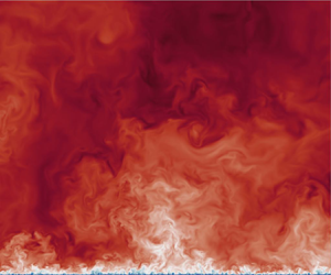
We begin by inspecting the instantaneous velocity fields in a cross-stream plane in figure 2. The figure highlights well that, as in all wall-bounded flows, the near-wall region with low-speed fluid becomes thinner as the Reynolds number increases, and finer-scale organization of the turbulent eddies is clearly visible. At the same time, large-sized towering eddies are well visible, which originate from the no-slip wall and extend up to the free surface. Despite differences in the details, the organization of the large-scale eddies seems to be similar, as will be confirmed quantitatively from the velocity spectra.
(a–f) Instantaneous streamwise velocity field (normalized by the mean free-surface velocity  $U_{FS}$) in a cross-stream plane, for the flow cases A–F, respectively, listed in table 1. Here, $y=0$ corresponds to the no-slip wall, and $y/h=1$ corresponds to the free surface. Note that only a limited part of the domain span is shown.

The flow organization in wall-parallel planes is considered in figure 3, where we show streamwise velocity contours near the no-slip wall and at the free surface, at two Reynolds numbers. The flow near the bottom wall is dominated by streaks of alternating high- and low-speed fluid, which are the hallmark of wall-bounded turbulence (Kline et al. Reference Kline, Reynolds, Schraub and Runstadler1967). Organization of the streaks on two different scales is quite apparent, with large-scale streaks whose size is similar at the two Reynolds numbers, and smaller-scale streaks whose size scales in wall units, and which hence become smaller at higher  ${{Re}}$. The large-scale streaks are the roots of the towering eddies noted previously. The imprinting of their tops is clear in the free-surface planes, which show the presence of streamwise-elongated eddies, whose spanwise size is similar at the two Reynolds numbers under scrutiny. Detailed information about the large-scale organization of the velocity field and the dynamical contributions of the large eddies can be found in the studies of Duan et al. (Reference Duan, Chen, Li and Zhong2020) and Yao et al. (Reference Yao, Chen and Hussain2022).
Instantaneous streamwise velocity fields in wall-parallel planes: (a,b) near the no-slip wall( $y^+=15$), and (c,d) at the free surface ( $y/h=1$), for (a,c) flow case C ( ${{Re}}_{\tau }=1000$), and (b,d) flow case F ( ${{Re}}_{\tau }=6000$).

Quantitative information about the flow organization can be gained from the spectral maps of  ${u}$, which are depicted in figure 4, where $k_{z}=2 {\rm \pi}/ \lambda _{z}$ is the relevant wavenumber for the spanwise direction. At low Reynolds number, a single peak is present, associated with the wall regeneration cycle (Jiménez & Pinelli Reference Jiménez and Pinelli1999). At higher Reynolds number, a secondary energetic site emerges, which is associated with outer-layer, large-scale motions (Hutchins & Marusic Reference Hutchins and Marusic2007). In between the two sites, a spectral ridge is present, corresponding to eddies with typical spanwise length scale $\lambda _{z} \sim y$, here encompassing over one decade in flow case F, which can be interpreted as the footprint of a hierarchy of wall-attached eddies as in Townsend's model (Townsend Reference Townsend1976). Although the spanwise spectra may seem noisy in the outer part, their time convergence has been checked carefully. Hence the observed undulations are rather the result of difficulties for the largest structures to be accommodated in the relatively narrow computational box. These effects are commented on in Appendix A.
(a–f) Variation of pre-multiplied spanwise spectral densities of fluctuating streamwise velocity with wall distance, for cases A–F, respectively. Wall distances and wavelengths are reported both in inner units (bottom, left axes) and in outer units (top, right axes). The dashed line denotes the channel free surface. The crosses denote the positions of the inner and outer energetic sites. Contour levels from 0.2 to 2.0 are shown, in intervals of 0.2.

The spectral maps are compared with those found in closed channel flow (Pirozzoli et al. Reference Pirozzoli, Bernardini and Orlandi2016), at matching Reynolds number ( ${{Re}}_{\tau }=2000$) in figure 5. Whereas the inner spectral peak is pretty much the same in the two flows (namely $\lambda _z^+ \approx 117$, at $y^+ \approx 13$), the outer peak is quite different. In fact, it occurs at a wavelength $\lambda _z = {\rm \pi}h / 2$, at a distance $y=0.28 h$ in the open channel, and it occurs at $\lambda _z = {\rm \pi}h / 3$, at a distance $y=0.18 h$ in the closed channel. This shows that in the open channel, the eddies that emerge from the no-slip wall can penetrate a greater distance, which also implies that the eddies are larger.
Comparison of spectral maps of fluctuating streamwise velocity in (a) open channel flow and(b) closed channel flow, at  ${{Re}}_{\tau }=2000$ (Bernardini, Pirozzoli & Orlandi Reference Bernardini, Pirozzoli and Orlandi2014). Wall distances and wavelengths are reported both in inner units (bottom, left axes) and in outer units (top, right axes). The dashed line denotes either the channel free surface or the channel centreline. Contour levels from 0.2 to 2.0 are shown, in intervals of 0.2. The second group of contours that appears in (b), for $y > h$, is the symmetric equivalence of the $y < h$ pattern, condensed visually because of use of a logarithmic scale.

Reynolds number effects on the streamwise velocity spectra are scrutinized more closely in figure 6, where we show spectral densities at the inner energy site location ( $y^+=15$), and at the outer site location ( $y/h=0.28$). Figure 6(a) clearly brings out universality of the spectra in inner units at the small scales. Additional energy appears at large scales as the Reynolds number increases, as a result of influence from the outer energy site (Marusic & Monty Reference Marusic and Monty2019). At intermediate wavelengths, there is also mild evidence for an ${E}_{u} \sim \lambda _{z}$ spectral range, which is also predicted from Townsend's attached-eddy model (Nickels et al. Reference Nickels, Marusic, Hafez and Chong2005). The inset of figure 6(a) further compares the spectrum at ${{Re}}_{\tau }=2000$ with the corresponding case of a closed channel. The figure suggests that the distribution of energy across the flow scales is very much the same in the two flows, with deviations occurring only at the largest scales, where the open channel (solid line) is found to have more energy, which results from the different outer-layer organization noticed previously, and in agreement with the results of Yao et al. (Reference Yao, Chen and Hussain2022). The spectra corresponding to the outer energy site, shown in figure 6(b), are comparatively more scattered, with change of the peak value with ${{Re}}$ and occasional peak splitting, again on account of the limited spanwise size of the box. Nevertheless, we notice a tendency for the spectra to collapse at the highest Reynolds numbers under scrutiny. This seems to be evidence that besides the well recognized universality of the inner-layer dynamics in inner units, the outer-layer dynamics also becomes universal in outer units, however only at sufficiently high Reynolds number, as argued previously by Dennis & Sogaro (Reference Dennis and Sogaro2014) for pipe flow.
Pre-multiplied spectral densities of streamwise velocity at (a)  $y^+=15$ and (b) $y/h=0.28$. The insets report a comparison with spectra in a closed channel at ${{Re}}_{\tau }=2000$ (solid lines indicate open channel, dashed lines indicate closed channel). The colour codes are as in table 1.

In figure 7, we show the inner-scaled mean velocity profiles obtained from the present DNS, which indicate agreement with a logarithmic distribution. Data fitting of the highest  ${{Re}}$ data yields $U^+ = 1/k \log y^+ + 4.21$, with Kármán constant $k=0.375$, hence smaller than reported for channel flow and in pipe flow (Lee & Moser Reference Lee and Moser2015; Pirozzoli et al. Reference Pirozzoli, Romero, Fatica, Verzicco and Orlandi2021). It is important to note that no significant deviations from the logarithmic distribution are found, also far from the wall. Detailed comparison with other internal flows at ${{Re}}_{\tau } \approx 2000$ is reported in figure 7(b), where we also show experimental data of open channel flow from Duan et al. (Reference Duan, Chen, Li and Zhong2020). The figure shows quite good agreement with experiments, and that the open channel flow has a weaker wake than the closed channel flow, which in turn has a weaker wake than pipe flow. Hence one could argue that the open channel flow is closest to the ideal situation of a wake-free flow, which is the optimal testbed to quantitatively probe the properties of the logarithmic layer. Similar observations were reported in the context of shear-free Couette–Poiseuille flow by Coleman et al. (Reference Coleman, Pirozzoli, Quadrio and Spalart2017).
(a) Inner-scaled mean velocity profiles obtained from the present DNS. (b) Comparison with the case of closed channel and pipe flow at  ${{Re}}_{\tau }=2000$. The dashed line in (a) refers to the logarithmic fit $U^+ = \log y^+ / 0.375 + 4.21$. In (b), the dashed line refers to the closed channel (Pirozzoli et al. Reference Pirozzoli, Bernardini and Orlandi2016), the dotted line to the case of pipe flow (Pirozzoli et al. Reference Pirozzoli, Romero, Fatica, Verzicco and Orlandi2021), and the blue circles to open channel experimental data at ${{Re}}_{\tau }=1903$ (Duan et al. Reference Duan, Chen, Li and Zhong2020). The colour codes are as in table 1.

More refined information on the behaviour of the mean velocity profile can be gained from inspection of the log-law diagnostic function, namely  $y^+ \, \mathrm {d} {U}^+ / \mathrm {d} y^+$, which is shown in figure 8, and whose constancy would imply the presence of a genuine logarithmic layer. The figure supports universality of the inner-scaled streamwise velocity for ${{Re}}_{\tau } \gtrsim 10^3$, up to $y^+ \approx 60$, where the diagnostic function attains a minimum. The figure also shows clear flattening of this indicator as the Reynolds number increases. At ${{Re}}_{\tau }=2000$, an extended flat region is first observed, for which the extrapolated Kármán constant is in perfect agreement with the results of Yao et al. (Reference Yao, Chen and Hussain2022), and in very good agreement with the data of Coleman et al. (Reference Coleman, Pirozzoli, Quadrio and Spalart2017) for Couette–Poiseuille flow with a zero-shear wall, from which $k \approx 0.37$ can be inferred. At higher ${{Re}}_{\tau }$ the Kármán constant seems to decrease a little, and at ${{Re}}_{\tau }=6000$ there is a well developed logarithmic layer up to $y/h=0.5$, corresponding to $k=0.375$. These values of the Kármán constant seem to differ somewhat from the commonly quoted value $k \approx 0.39$ for closed channel and pipe flow (Lee & Moser Reference Lee and Moser2015; Pirozzoli et al. Reference Pirozzoli, Romero, Fatica, Verzicco and Orlandi2021; Hoyas et al. Reference Hoyas, Oberlack, Alcántara-Ávila, Kraheberger and Laux2022). However, in those cases, significant scatter and ambiguity persist on how the fitting is carried out, in the absence of extended regions with flat diagnostic functions. In fact, systematic deviations from a logarithmic distribution are observed in internal flows, which are typically modelled through additional linear terms (Afzal Reference Afzal1982; Jiménez & Moser Reference Jiménez and Moser2007; Luchini Reference Luchini2017). In particular, the latter study attributed the occurrence of additional linear terms in the overlap layer expansion of the mean velocity profile in internal flows to the effect of the imposed pressure gradient. The case of the open channel flow, in which a pressure gradient is present, but deviations from the log law are not evident, seems to rule out such explanation. On the other hand, the present findings seem to corroborate the interpretation given by Monkewitz (Reference Monkewitz2021), that the late start of the logarithmic layer in internals flows is due to intrusions from the opposite wall, which in fact are not present in the open channel flow. Differences with other canonical wall-bounded flows are made more explicit in figure 8(b), which makes it quite clear that the log-law diagnostic function is much flatter in the present case than in other flows, and even closed channel flow at substantially higher Reynolds number (Hoyas et al. Reference Hoyas, Oberlack, Alcántara-Ávila, Kraheberger and Laux2022) exhibits a much wider range of variation.
Log-law diagnostic function for mean streamwise velocity, as a function of (a) inner-scaled and(b) outer-scaled wall distance. The dashed horizontal line denotes the inverse Kármán constant,  $1/0.375$. Lines denote present DNS data, with colour code as in table 1. Symbols denote data for closed channel flow at ${{Re}}_{\tau }=5200$ (triangles, Lee & Moser Reference Lee and Moser2015), boundary layer at ${{Re}}_{\tau }=6115$ (circles, Österlund et al. Reference Österlund, Johansson, Nagib and Hites2000), and pipe flow at ${{Re}}_{\tau }=6000$ (squares, Pirozzoli et al. Reference Pirozzoli, Romero, Fatica, Verzicco and Orlandi2021).

The structure of the wake region of the open channel is examined in detail in figure 9, where the mean velocity profiles are shown in defect form. Full outer-layer similarity is achieved even at the lowest Reynolds numbers under scrutiny, starting at  $y/h \approx 0.2$. The defect logarithmic profile
 \begin{equation} U_{FS}^+{-} U^+{=} - \frac 1k \log (y/h) + B \end{equation}
fits the data very well with  $k=0.375$, and with additive constant $B=0.128$. Deviations from the outer log law seem to be very minor, and concentrated in a narrow layer adjacent to the free surface.
Defect velocity profiles for DNS of open channel flow, in (a) linear and (b) semi-logarithmic scale. The dashed grey line marks the outer-layer logarithmic fit  $U^+_{FS}-U^+ = -0.128 - 1/0.375 \log (y/h)$.

The previous observations regarding the structure of the mean velocity field can be leveraged to deduce that the dependence of the bulk and mean free-surface velocity on the friction Reynolds number should be logarithmic. This is checked in figure 10, where we show the mean velocity at the free surface and the bulk velocity normalized by the friction velocity, as functions of the friction Reynolds number. Consistently with the case of internal flows (e.g. Monkewitz Reference Monkewitz2021), the data in fact support logarithmic increase with  ${{Re}}_{\tau }$, according to
 \begin{equation} u_{b}^+{=} \frac 1{k} \log {{Re}}_{\tau} + B_b,\quad U_{FS}^+{=} \frac 1{k_{FS}} \log {{Re}}_{\tau} + B_{FS}, \end{equation}
with data fitting suggesting  $k_{FS} \approx k=0.375$, and $B_b=1.57$, $B_{FS}=4.02$. As a result of the observed identity (or very close vicinity) of the Kármán constant for the centreline and for the bulk velocity, figure 10(b) highlights that their ratio approaches unity at large ${{Re}}$, supporting the inference that open channel flow asymptotes to plug flow in the infinite-Reynolds-number limit; see Pullin, Inoue & Saito (Reference Pullin, Inoue and Saito2013). Regarding that study, it is worthwhile noticing that one of the assumptions made in the analysis is that the wall-normal location of the onset of the logarithmic region is either finite or increases no faster than ${{Re}}_{\tau }$. Interpreting the near-wall minimum of the diagnostic function in figure 8 as the root of the (near) logarithmic layer, our data well support that assumption. However, as figure 10(b) suggests, this trend is extremely slow.
(a) Mean free surface velocity ( $U_{FS}$) and bulk velocity, and (b) their ratio, as functions of the friction Reynolds number. DNS data are shown as circle symbols, and the corresponding logarithmic fits are shown as dashed lines. Black is used for $U_{FS}$, and purple for $u_b$.

Equations (3.2a,b) can be exploited in order to determine friction relationships for flow in smooth open channels, namely
 \begin{equation} \sqrt{\frac2{C_f}}= \frac 1k \log \left( {{Re}}_b\,\sqrt{\frac{C_f}2} \right) + B_b - \frac 1k,\quad \sqrt{\frac2{c_f}}= \frac 1k \log \left( {{Re}}_{FS}\,\sqrt{\frac{c_f}2} \right) + B_{FS}, \end{equation}
whence the friction coefficient (either  $C_f = 2 \tau _w / (\rho u_b^2)$ or $c_f = 2 \tau _w / ( \rho U_{FS}^2)$) can be evaluated as an implicit function of the bulk Reynolds number, or of the Reynolds number at the free surface ( ${{Re}}_{FS}=U_{FS} h / \nu$).
The distributions of the velocity variances along the coordinate directions are shown in figure 11, in inner scaling. As is well established (Marusic & Monty Reference Marusic and Monty2019), the streamwise ( $u$) and spanwise ( $w$) velocity fluctuations show slow increase with the Reynolds number, with commonly accepted logarithmic growth as in Townsend's attached-eddy model (Townsend Reference Townsend1976). On the other hand, the wall-normal velocity fluctuations seem to level off to maximum value approximately $1.30$ (Smits et al. Reference Smits, Hultmark, Lee, Pirozzoli and Wu2021). It is remarkable that the general growth of the longitudinal and spanwise fluctuations is more evident in the outer layer, and in fact it has long been argued about the possible occurrence of a secondary peak of $\langle u^2\rangle$, besides the primary buffer-layer peak. Experiments carried out in the Superpipe (Hultmark et al. Reference Hultmark, Vallikivi, Bailey and Smits2012) and CICLoPE (Willert et al. Reference Willert, Soria, Stanislas, Klinner, Amili, Eisfelder, Cuvier, Bellani, Fiorini and Talamelli2017) facilities indeed support the occurrence of such a peak at ${{Re}}_{\tau } \gtrsim 10^4$. Whereas DNS data do not reach sufficiently high ${{Re}}_{\tau }$ to show this secondary peak, it appears that in flow case F, the streamwise velocity variance has attained a nearly horizontal inflectional point at $y^+ \approx 140$. Comparison with the data from closed channels shows generally higher values of all fluctuating velocity components, which is consistent with additional energy resulting from the more intense outer-layer eddies. This also yields higher probability that the outer-layer peaks of $\langle u^2\rangle$, if found, would occur earlier in the open channel than in the closed channel. Additional differences are related to the behaviour of the velocity variances near the free surface, where of course $\langle v^2\rangle$ must go to zero as a consequence of the rigid-lid assumption, and where the horizontal velocity variances show some pile-up and become very similar in magnitude (Nezu Reference Nezu2005). Comparison with the experimental data of Duan et al. (Reference Duan, Chen, Li and Zhong2020) in figures 11(a,b) shows generally good agreement, especially in the outer part of the flow. Differences observed towards the wall, and especially overestimation of the vertical velocity variance in the experiment, are the likely result of well-known difficulties in measuring in the vicinity of walls.
Distribution of velocity variances (a–c) and trend of peak streamwise velocity variance with Reynolds number (d). The blue circles in (a,b) denotes experimental data of Duan et al. (Reference Duan, Chen, Li and Zhong2020), at  ${{Re}}_{\tau }=1903$. The circles in (d) denote the present open channel data, and the squares the closed channel data of Lee & Moser (Reference Lee and Moser2015), at ${{Re}}_{\tau } = 550, 1000, 2000, 5200$. The dashed and dot-dashed data denote the corresponding logarithmic fits, and the dotted line the trend predicted by Chen & Sreenivasan (Reference Chen and Sreenivasan2021).

Figure 11(d) displays the trend of the streamwise velocity variance with  ${{Re}}_{\tau }$. This quantity is the subject of a lot of theoretical interest, and in particular its behaviour in the infinite- ${{Re}}$ limit. In fact, the attached-eddy model (Townsend Reference Townsend1976; Marusic & Monty Reference Marusic and Monty2019) predicts that it should be increasing logarithmically with ${{Re}}_{\tau }$, on account of influence from distant, outer-layer eddies, which would imply a violation of the strict wall scaling. On the other hand, arguments have been made recently that this peak should stay finite, as a result of saturation of growth of the turbulence kinetic energy dissipation rate at the wall (Chen & Sreenivasan Reference Chen and Sreenivasan2021). Although difference between slow logarithmic growth and attainment of an asymptotic value is quite tenuous in practice, the theoretical interest is high as in the latter case universality of wall scaling would be restored eventually. The data shown in figure 11(d) generally seem to support logarithmic growth, with slope approximately $0.63$, very close to the case of closed channel (Lee & Moser Reference Lee and Moser2015), and as suggested from a collection of DNS and experiments on boundary layers (Marusic, Baars & Hutchins Reference Marusic, Baars and Hutchins2017). At the same time, the theoretical prediction of Chen & Sreenivasan (Reference Chen and Sreenivasan2021) (see the dotted purple line of figure 11d) seems to conform well with DNS data at the highest Reynolds number achieved. Discriminating between these two trends would probably require much higher Reynolds numbers than are currently feasible in DNS of wall-bounded flows.
Whereas our DNS data cannot be used to evaluate directly the theoretical predictions owing to limited achievable Reynolds number, they can be used to better scrutinize the foundations of the theoretical arguments. The main argument made by Chen & Sreenivasan (Reference Chen and Sreenivasan2021), although not strictly justified mathematically, was that since turbulence kinetic energy production is bounded, the wall dissipation must also stay bounded. Letting  $P = - \left \langle u v \right \rangle \mathrm {d} U / \mathrm {d} y$ be the turbulence kinetic energy production rate, and $\epsilon _{11} = \nu \left \langle | \nabla u |^2 \right \rangle$ be the dissipation rate of the streamwise velocity variance, those authors argued that the wall limiting value of $\epsilon _{11}$ should scale as
 \begin{equation} {\epsilon_{11}}_w^+{=} 1/4 - \beta / {{Re}}_{\tau}^{1/4}, \end{equation}
with  $\beta$ a suitable constant. In figure 12(a), we explore deviations of ${\epsilon _{11}}_w$ and of the peak turbulence kinetic energy production, say $P_{PK}$, from their asymptotic value, namely $1/4$. According to analytical constraints (Pope Reference Pope2000), we find that production tends to its asymptotic value quite rapidly, as approximately $1/{{Re}}_{\tau }$. Consistent with (3.4), the wall dissipation rate also tends to $1/4$, more or less at the predicted rate, thus validating the first assumption empirically. The next argument advocated by Chen & Sreenivasan (Reference Chen and Sreenivasan2021) is that wall balance between viscous diffusion and dissipation and Taylor series expansion of the streamwise velocity variance near the wall yields
 \begin{equation} \langle u^2 \rangle^+{\sim} \epsilon_{{11w}}^+ {y^+}^2, \end{equation}
whence, from assumed invariance of the peak location of  $\langle u^2 \rangle$ (say, $y_{PK}^+$), saturation of growth of the peak velocity variance would follow. Figure 12(b) reports the position of the streamwise velocity variance peak position as a function of ${{Re}}_{\tau }$, as inferred from cubic spline interpolation of the DNS data. Also accounting for uncertainty associated with data interpolation, the figure suggests that this second assumption may not be valid, as the (inner-scaled) peak position shifts away from the wall at increasing ${{Re}}_{\tau }$, with non-negligible effect on the peak variance as it appears in squared form in (3.5). As a consequence, logarithmic growth of the peak velocity variance would still be possible even in the presence of saturation of the wall dissipation rate, at least based on DNS data in the currently accessible range of Reynolds numbers.
(a) Distributions of peak turbulence production ( $P_{PK}$, squares), and wall dissipation of streamwise velocity variance ( $\epsilon _{{11w}}$, circles). (b) Peak position of streamwise velocity variance. In (a), the dot-dashed and dotted lines denote fits of $P_{PK}$ and $\epsilon _{{11w}}$ in their tendency to the respective assumed asymptotic values.

It is well established that the intensity of wall pressure fluctuations in boundary layers and channels increases logarithmically with the Reynolds number, when scaled by the mean wall shear stress (Willmarth Reference Willmarth1975; Farabee & Casarella Reference Farabee and Casarella1991; Hu, Morfey & Sandham Reference Hu, Morfey and Sandham2006; Tsuji et al. Reference Tsuji, Fransson, Alfredsson and Johansson2007; Jiménez & Hoyas Reference Jiménez and Hoyas2008; Sillero, Jiménez & Moser Reference Sillero, Jiménez and Moser2013). Tsuji et al. (Reference Tsuji, Fransson, Alfredsson and Johansson2007) found a similar trend for the peak pressure variance, which occurs at approximately  $y^+=30$. Jiménez & Hoyas (Reference Jiménez and Hoyas2008) suggested that this logarithmic increment should be attributed to a growing hierarchy of self-similar wall-attached eddies (Townsend Reference Townsend1976; Hwang Reference Hwang2015; Marusic & Monty Reference Marusic and Monty2019). Pressure, like the wall-parallel velocity components, can indeed be regarded as a wall-attached quantity (Bradshaw Reference Bradshaw1967), which explains why profiles of the pressure variance also follow a logarithmic trend with respect to the wall distance. The same behaviour can, however, also be predicted based on inner/outer layer overlap arguments (Panton, Lee & Moser Reference Panton, Lee and Moser2017). Mehrez et al. (Reference Mehrez, Philip, Yamamoto and Tsuji2019) explored the DNS database of closed channel flow at friction Reynolds number up to 4000, and found that the logarithmic trend shows up only for ${{Re}}_\tau \gtrsim 500$.
The distributions of the pressure variances obtained from the present DNS are displayed in figure 13(a). These are found to remain nearly constant within the viscous sublayer (say,  $y^+ \le 5$), then increase to attain a peak value at $y^+ \approx 30$, and decrease thereafter. A region with distinctly logarithmic decrease is found from $y^+ \approx 100$ basically all the way to the free surface, with slight deviations. As the Reynolds number increases, the pressure variances at the wall and their peak values increase systematically, whereas the value at the free surface is not much affected. Compared with the variances in closed channels (dashed lines), we note that pressure fluctuations in open channels tend to be a bit less in the buffer layer, whereas they are virtually identical towards the wall and in the outer layer. When plotted against outer wall coordinates, the logarithmic portions of the pressure variance distribution collapse for ${{Re}}_\tau \gtrsim 500$, consistent with the case of closed channel flow (Mehrez et al. Reference Mehrez, Philip, Yamamoto and Tsuji2019). Expressing the outer distribution as
 \begin{equation} \langle p^2 \rangle^+ (y/h)= A_p \log \left( y/h \right) + B_p, \end{equation}
curve fitting within the range  $y = 0.02h\unicode{x2013}0.5h$ for flow case F yields the values of parameters $A_p=-2.40$ and $B_p=1.23$, with error $0.4\,\%$.
(a) Wall-normal distribution of pressure variance, and (b) wall pressure variance as a function of Reynolds number. In (a), the dashed lines correspond to closed channel flow DNS data (Lee & Moser Reference Lee and Moser2015) at  ${{Re}}_{\tau } = 180, 550, 1000, 2000, 5200$, and the grey line denotes the logarithmic fit given in (3.6). In (b), circles are used for the open channel data, and squares for the closed channel data; the dashed lines denote the logarithmic data fit given in (3.7). Refer to table 1 for colour codes.

We further report the wall pressure variances as a function of  ${{Re}}_{\tau }$ in figure 13(b). With exclusion of the lowest Reynolds number case at ${{Re}}_\tau \approx 180$, the wall pressure variances can be well characterized in terms of the log law
 \begin{equation} \langle p^2_w \rangle^+{=}2.22\log {{Re}}_\tau -8.99, \end{equation}
thus supporting theoretical inferences quite well. The logarithmic growth rate seems to be identical to that for closed channel flow.
4. Concluding comments
The study of flow in an open channel has the merit of isolating the effect of wall-imposed shear from other complicating effects, for instance due to the presence of opposing walls (as in closed channel flow) or geometrical confinement in general (as in pipe flow). Hence, despite limited practical impact, as by far most instances of open channel flow occur over rough beds, we believe that the theoretical interest of studying open channel flow is quite large. We find that flow in an open channel is a very good candidate to observe the log law of the wall in its ‘pure’ form, and in fact a clear logarithmic layer is present even at ‘modest’ Reynolds number (Yao et al. Reference Yao, Chen and Hussain2022), and in the present DNS there is a clear evidence that a genuine logarithmic layer exists, at least up to half of the channel depth. The estimated Kármán constant is found to increase a little with the Reynolds number, starting from  $k=0.363$ at ${{Re}}_{\tau }=2000$ (in perfect agreement with Yao et al. Reference Yao, Chen and Hussain2022), to arrive at $k=0.375$ at ${{Re}}_{\tau }=6000$. A certain variability of the Kármán constant was in fact noticed in previous systematic experimental studies (Nagib & Chauhan Reference Nagib and Chauhan2008), which is possibly related to finite- ${{Re}}$ effects. In any case, the scenario is much clearer than in internal flows such as closed channels and pipes. In the case of a closed channel, convincing evidence for a (small) region with flat behaviour of the log-law diagnostic function has come only recently from DNS at ${{Re}}_{\tau }=10\,000$ (Hoyas et al. Reference Hoyas, Oberlack, Alcántara-Ávila, Kraheberger and Laux2022). Otherwise, data at lower ${{Re}}$ seem to feature obvious deviations from the expected logarithmic behaviour that are traditionally modelled as additional linear terms (Jiménez & Moser Reference Jiménez and Moser2007; Luchini Reference Luchini2017), and the Kármán constant is extrapolated based on fitting those compound distributions to the DNS data (e.g. Pirozzoli et al. Reference Pirozzoli, Romero, Fatica, Verzicco and Orlandi2021). The resulting value of the Kármán constant is then $k=0.38\unicode{x2013}0.39$, hence a bit higher than found in the open channel. It is also noteworthy that Coleman et al. (Reference Coleman, Pirozzoli, Quadrio and Spalart2017) carried out numerical simulation of the Couette–Poiseuille flow (namely, channel flow with combined relative motion of the walls and imposed pressure gradient) under conditions such that one of the walls has zero shear, and found very similar behaviour, namely an extended logarithmic layer with Kármán constant $k=0.37$. In our opinion, universality of wall turbulence in the near-wall region requires universality of the Kármán constant, hence we believe that variations observed in all studies so far are related to limited Reynolds number, or to numerical and experimental uncertainties, or effects of geometrical confinement, or all of these. Study of flow in open channels has the merit of removing at least the latter contaminating effects. Regarding deviations from the log law in internal flows, Luchini (Reference Luchini2017) argued that additive linear terms should be present on account of the driving pressure gradient. However, a driving force is present in the open channel flow, but clear deviations from logarithmic behaviour are not observed. Hence it seems more reasonable to accept that deviations or late occurrence of a logarithmic behaviour in internal flows is rather due to geometric confinement effects, and specifically to influence of the opposing wall in closed channels, as argued by Monkewitz (Reference Monkewitz2021).
Study of flow in open channels also bears some interesting implications regarding interactions between the inner and outer wall layers, and their universality. Our study corroborates previous findings (Duan et al. Reference Duan, Chen, Li and Zhong2020; Yao et al. Reference Yao, Chen and Hussain2022) that large outer-layer eddies form in open channels, which are larger and more energetic than in closed channels. Here, we find evidence that these eddies also become universal at sufficiently high Reynolds number, when lengths are expressed in outer units. This would support universality of the outer-layer dynamics, in addition to the well-recognized universality of the inner-layer dynamics, as proposed by Dennis & Sogaro (Reference Dennis and Sogaro2014). The signature of wall-attached eddies is also evident in the spectral footprints, as well as in the statistics of the spanwise velocities and pressure fluctuations, which exhibit extended logarithmic layers. The imprinting of the energetic outer-layer eddies manifests itself with higher values of the velocity variances. This in turn translates to earlier occurrence of the (possible) outer-layer peak, which we believe can be observed in open channel flow at  ${{Re}}_{\tau } \approx 10^4$. Regarding the growth of the inner-layer peak of the streamwise velocity variance, available evidence seems to support logarithmic growth with ${{Re}}_{\tau }$, although firm asymptotic trends are difficult to discern. Specifically, we find empirical evidence that the turbulence kinetic energy dissipation rate at the wall reaches an asymptote, as argued by Chen & Sreenivasan (Reference Chen and Sreenivasan2021), but we also find that the peak location at which the streamwise velocity variance is maximum slowly varies with ${{Re}}_{\tau }$, which would allow for logarithmic growth of the peak value even if the growth of the wall dissipation was to saturate.
In summary, we find that, besides its intrinsic interest, open channel flow can be exploited usefully as a testbed to explore the behaviour of wall turbulence at extreme Reynolds number, and especially to disentangle various complicating effects. Follow-up studies will also include analysis of the process of exchange of mass and momentum at the free surface at computationally high Reynolds number.
Acknowledgements
We acknowledge CINECA and EuroHPC JU for awarding this project access to Leonardo supercomputing hosted at CINECA.
Funding
This research received no specific grant from any funding agency, commercial or not-for-profit sectors.
Declaration of interests
The author report no conflict of interest.
Appendix A. Box and grid sensitivity analysis
The wall-normal stretching is designed after the prescriptions set by Pirozzoli & Orlandi (Reference Pirozzoli and Orlandi2021), to resolve the steep near-wall velocity gradients and the local Kolmogorov scale away from the wall. Referring to the no-slip wall, the grid points are distributed according to
 \begin{equation} y^+(j) = \frac 1{1+(j/j_b)^2} \Biggl[ {\rm \Delta} y^+_w\,j + \left( \frac 34\,\alpha c_{\eta} j \right)^{4/3} (j/j_b)^2 \Biggr], \end{equation}
where  ${\rm \Delta} y^+_w=0.05$ is the wall distance of the first grid point, $j_b=40$ defines the grid index at which transition between the near-wall and the outer mesh stretching takes place, and $c_{\eta }=0.8$ guarantees resolution of wavenumbers up to $k_{max} \eta = 1.5$. The grid points are also more mildly clustered towards the free-slip wall to guarantee proper resolution of the free-surface layer. Based on preliminary studies, we still use the stretching function (A1), however, with $j_b=15$, $c_{\eta }=1.03$. The two distributions are smoothly connected at $y/h=0.73$, as shown in figure 14.
Distribution of wall-normal coordinate ( $y_j$, solid line) and corresponding grid spacing ( ${\rm \Delta} y$, dashed line) for flow case F, as a function of the grid index ( $j$).
$j$).

The wall-normal resolution is checked a posteriori in figure 15, where we show the grid spacing expressed in local Kolmogorov units, which is found to be no larger than  $2.6$, throughout the channel. Adequate resolution of the free-surface layer is also evident in figure 15, which shows that it is resolved with ten collocation points at least.
(a) Wall-normal grid resolution, in terms of grid spacing in local Kolmogorov units. (b) Detail of the root-mean-square spanwise vorticity near the free surface. The colour codes are as in table 1.

Sensitivity of the computed results to the computational box size and grid resolution has also been verified by carrying out additional simulations at  ${{Re}}_b = 20\,000$, as listed in table 2. As one could argue from the instantaneous flow visualizations of figure 2, spanwise confinement effects are expected, especially towards the free surface, where structures are wider. This is why flow cases C-M, C-W, C-WW were carried out, corresponding to box width up to $L_x = 5 {\rm \pi}h$. Some confinement effect is in fact noticeable in the spectral maps (see figure 16), which show some variability of the outer spectral peak position and wavelength. This is made quantitative in table 2, where the outer peak wavelength is reported. Apparently, having a wider domain allows the outer eddies to become a little larger. The effect of rearrangement of the outer part of the spectral maps is, however, quite small when it comes to the one-point statistics, which we show in figure 17. In fact, scatter in the mean and first-order statistics, shown in figure 17(a), is much less than $1\,\%$, hence within the statistical sampling error. This error is magnified when the diagnostic function is reported, as in figure 17(b). In this case, the scatter is larger, but not to the extent of modifying the results qualitatively.
Computational parameters for box and grid sensitivity study. For all cases,  ${{Re}}_b=20\,000$. Here, $N_x$, $N_y$ and $N_z$ are the numbers of grid points in the streamwise, wall-normal and spanwise directions, respectively, ${{Re}}_{\tau } = u_{\tau } h / \nu$ is the friction Reynolds number, $\lambda _{max}$ is the wavelength corresponding to the outer spectral peak, and $ETT$ is the time interval used to collect the flow statistics, in units of the eddy turnover time $h/u_{\tau }$.

Variation of pre-multiplied spanwise spectral densities of instantaneous streamwise velocity with wall distance for the flow cases listed in table 2. Wall distances and wavelengths are reported both in inner units (bottom, left axes), and in outer units (top, right axes). The dashed line denotes the channel free surface. The crosses denote the positions of the inner and outer energetic sites. Contour levels from 0.2 to 2.0 are shown, in intervals of 0.2.

Box and grid sensitivity study for one-point statistics: (a) inner-scaled mean velocity profiles and streamwise velocity variances, and (b) log-law diagnostics function. The dashed line in (a) refers to the logarithmic fit  $U^+ = \log y^+ / 0.375 + 4.21$. The dashed horizontal line in (b) denotes the inverse Kármán constant $1/0.375$. The line style is as in table 2.


 Open access