


1 Introduction
1.1 Motivation
The study of droplet–turbulence interaction is important for many industrial processes as well as for fundamental understanding of dispersed two phase flows. It has been the subject of intense research over the last few decades. However, because of its complexity, involvement of large number of influencing parameters and limitations in numerical and experimental tools, the physics of two phase flows is yet to be well understood. Broadly, the interaction between the two phases can be classified into two categories. First, the effect of droplets/particles on momentum/energy exchange between the two phases (see Squires & Eaton Reference Squires and Eaton1990; Kulick, Fessler & Eaton Reference Kulick, Fessler and Eaton1994; Boivin, Simonin & Squires Reference Boivin, Simonin and Squires1998; Sundaram & Collins Reference Sundaram and Collins1999; Ferrante & Elghobashi Reference Ferrante and Elghobashi2003; Hwang & Eaton Reference Hwang and Eaton2006, among others). Second, the dispersion of particles by the carrier phase turbulence, whose key features essentially include preferential particle concentration (Lazaro & Lasheras Reference Lazaro and Lasheras1992; Longmire & Eaton Reference Longmire and Eaton1992; Wang & Maxey Reference Wang and Maxey1993; Fessler, Kulick & Eaton Reference Fessler, Kulick and Eaton1994; Wood, Hwang & Eaton Reference Wood, Hwang and Eaton2005) and the effect of carrier phase turbulence on particle dynamics, in particular particle acceleration (Ayyalasomayajula et al. Reference Ayyalasomayajula, Gylfason, Collins, Bodenschatz and Warhaft2006; Bec et al. Reference Bec, Biferale, Boffetta, Celani, Cencini, Lanotte, Msacchio and Toschi2006) and settling velocity (Wang & Maxey Reference Wang and Maxey1993; Aliseda et al. Reference Aliseda, Cartellier, Hainaux and Lasheras2002; Yang & Shy Reference Yang and Shy2005). It is interesting to note that the turbulence of the carrier phase may disperse the particles in such a way that its consequence can in turn result in alteration of the turbulence. The turbulence modulation due to droplets in a confined polydispersed spray is considered by Sahu, Hardalupas & Taylor (Reference Sahu, Hardalupas and Taylor2014) from the perspective of the droplet–gas spatial velocity correlations specifically focusing on the role of large-scale flow structures on the interphase momentum transfer. The present paper aims at developing further understanding on the influence of turbulence on droplet dispersion in the confined spray and the role of fluctuations of droplet concentration on turbulence modulation of the carrier phase. Throughout the paper, the terms ‘particle’ and ‘droplet’ would be synonymously used.
Though the above mentioned studies have led the way for deeper understanding of the physics of particle–turbulence interaction, there exists certain other issues on droplet dispersion by turbulence which need attention: (i) the previous works have been largely based on monodisperse particles (or narrow particle size distribution) interacting with carrier phase turbulence, while in most practical as well as natural processes polydisperse particles are involved. The degree to which turbulent eddies can modify the instantaneous concentration field depends on the droplet Stokes number ( $St$
). (Stokes number is defined as the ratio of droplet response time to any suitable turbulent eddy time scale. It characterizes the response of droplets to fluid motion at the corresponding length scale.) When the droplet size distribution is broad, it is necessary to understand the influence of different Stokes number on droplet dispersion. However, only few studies have considered polydispersed droplets, for instance, see Lazaro & Lasheras (Reference Lazaro and Lasheras1992), Kiger & Lasheras (Reference Kiger and Lasheras1995), Aliseda et al. (Reference Aliseda, Cartellier, Hainaux and Lasheras2002), Ferrand et al. (Reference Ferrand, Bazile, Boree and Charnay2003), Saw et al. (Reference Saw, Shaw, Ayyalasomayajula, Chuang and Gylfason2008, Reference Saw, Salazar, Collins and Shaw2012a
,Reference Saw, Shaw, Salazar and Collins
b
). (ii) As pointed out by Fessler et al. (Reference Fessler, Kulick and Eaton1994), it is not only important to know what particle size is most preferentially concentrated but also at what scale the concentration occurs. However, it is still debatable to conclude which turbulent scale of the flow (whether the integral length scale, Yang & Le (Reference Yang and Le1998) or the Kolmogorov length scale, Wang & Maxey (Reference Wang and Maxey1993) or some other scale) plays the most important role in droplet–turbulence interaction and contradictory remarks have been reported in the literature. (iii) The influence of gravity on droplet dispersion needs further investigation since it may affect the magnitude of local droplet concentration fluctuations and this has not been quantified in detail. (iv) An important issue, which has not gained much attention, is the effect of unsteady mass loading on momentum transfer between the two phases. Due to preferential concentration, particles tend to accumulate in some regions of the flow. Thus, both dense and dilute regions of particle are created in the flow causing spatial and temporal fluctuations of particle concentration, which may alter the turbulence level in the carrier phase flow.
$St$
). (Stokes number is defined as the ratio of droplet response time to any suitable turbulent eddy time scale. It characterizes the response of droplets to fluid motion at the corresponding length scale.) When the droplet size distribution is broad, it is necessary to understand the influence of different Stokes number on droplet dispersion. However, only few studies have considered polydispersed droplets, for instance, see Lazaro & Lasheras (Reference Lazaro and Lasheras1992), Kiger & Lasheras (Reference Kiger and Lasheras1995), Aliseda et al. (Reference Aliseda, Cartellier, Hainaux and Lasheras2002), Ferrand et al. (Reference Ferrand, Bazile, Boree and Charnay2003), Saw et al. (Reference Saw, Shaw, Ayyalasomayajula, Chuang and Gylfason2008, Reference Saw, Salazar, Collins and Shaw2012a
,Reference Saw, Shaw, Salazar and Collins
b
). (ii) As pointed out by Fessler et al. (Reference Fessler, Kulick and Eaton1994), it is not only important to know what particle size is most preferentially concentrated but also at what scale the concentration occurs. However, it is still debatable to conclude which turbulent scale of the flow (whether the integral length scale, Yang & Le (Reference Yang and Le1998) or the Kolmogorov length scale, Wang & Maxey (Reference Wang and Maxey1993) or some other scale) plays the most important role in droplet–turbulence interaction and contradictory remarks have been reported in the literature. (iii) The influence of gravity on droplet dispersion needs further investigation since it may affect the magnitude of local droplet concentration fluctuations and this has not been quantified in detail. (iv) An important issue, which has not gained much attention, is the effect of unsteady mass loading on momentum transfer between the two phases. Due to preferential concentration, particles tend to accumulate in some regions of the flow. Thus, both dense and dilute regions of particle are created in the flow causing spatial and temporal fluctuations of particle concentration, which may alter the turbulence level in the carrier phase flow.
In order to address these issues, apart from examining the preferential accumulation of droplets, it is also essential to estimate the correlation between instantaneous fluctuations of droplet concentration and velocity of both dispersed and carrier phases. Such correlations can quantify the influence of large-scale flow structures of the carrier phase on droplet dispersion. In addition, these correlation terms appear in the model equation describing the turbulent kinetic energy (TKE) of the carrier phase in a droplet-laden flow as derived by Elghobashi & Abou-Arab (Reference Elghobashi and Abou-Arab1983) or Chen & Wood (Reference Chen and Wood1985) (based on Eulerian–Eulerian description of fluid–droplet phases) and used by e.g. Kulick et al. (Reference Kulick, Fessler and Eaton1994):
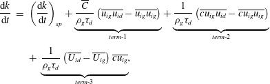 $$\begin{eqnarray}\displaystyle \frac{\text{d}k}{\text{d}t} & = & \displaystyle \left(\frac{\text{d}k}{\text{d}t}\right)_{\text{sp}}+\underbrace{\frac{\overline{C}}{{\it\rho}_{g}{\it\tau}_{d}}\left(\overline{u_{ig}u_{id}}-\overline{u_{ig}u_{ig}}\right)}_{term\text{-}1}+\underbrace{\frac{1}{{\it\rho}_{g}{\it\tau}_{d}}\left(\overline{cu_{ig}u_{id}}-\overline{cu_{ig}u_{ig}}\right)}_{term\text{-}2}\nonumber\\ \displaystyle & & \displaystyle +\,\underbrace{\frac{1}{{\it\rho}_{g}{\it\tau}_{d}}\left(\overline{U_{id}}-\overline{U_{ig}}\right)\overline{cu_{ig}}}_{term\text{-}3},\end{eqnarray}$$
where $U$
and
$U$
and $u$
denote the instantaneous and fluctuating velocity, respectively, subscripts
$u$
denote the instantaneous and fluctuating velocity, respectively, subscripts $d$
and
$d$
and $g$
refer to droplet and gas phases, respectively, and
$g$
refer to droplet and gas phases, respectively, and $i$
refers to the component of the Cartesian reference system.
$i$
refers to the component of the Cartesian reference system. $C$
and
$C$
and $c$
are the instantaneous and fluctuating droplet concentration, overbar denotes time averaging and
$c$
are the instantaneous and fluctuating droplet concentration, overbar denotes time averaging and ${\it\tau}_{d}$
is the droplet relaxation time. The quantity
${\it\tau}_{d}$
is the droplet relaxation time. The quantity $C/{\it\rho}_{g}$
is the instantaneous mass loading of droplets in the fluid flow. The first term on the right-hand side comprises the production, dissipation and transport terms in the single phase fluid. The remaining terms are denoted as ‘term-1’, ‘term-2’ and ‘term-3’ in the order of their appearance in (1.1). These terms, derived by assuming a linear drag law for droplets, represent modification of turbulent kinetic energy due to droplets depicting the interaction. An important feature of the above equation is the explicit appearance of correlations both with and without considering the fluctuations of droplet concentration. This provides an opportunity to compare different mechanisms governing the interphase energy transfer, for instance, whether it is the drag due to instantaneous slip velocity, the local mass loading, the mean slip velocity or a combination of those that plays the key role in dynamics of droplet–gas interaction. However, (1.1) does not consider the wake effects of droplets on carrier fluid, hence is valid for small droplets only (the droplet size is smaller than the smallest length scale of the carrier phase flow).
$C/{\it\rho}_{g}$
is the instantaneous mass loading of droplets in the fluid flow. The first term on the right-hand side comprises the production, dissipation and transport terms in the single phase fluid. The remaining terms are denoted as ‘term-1’, ‘term-2’ and ‘term-3’ in the order of their appearance in (1.1). These terms, derived by assuming a linear drag law for droplets, represent modification of turbulent kinetic energy due to droplets depicting the interaction. An important feature of the above equation is the explicit appearance of correlations both with and without considering the fluctuations of droplet concentration. This provides an opportunity to compare different mechanisms governing the interphase energy transfer, for instance, whether it is the drag due to instantaneous slip velocity, the local mass loading, the mean slip velocity or a combination of those that plays the key role in dynamics of droplet–gas interaction. However, (1.1) does not consider the wake effects of droplets on carrier fluid, hence is valid for small droplets only (the droplet size is smaller than the smallest length scale of the carrier phase flow).
While not much information is available on the relative magnitude of the contained terms in (1.1) as pointed out by Kulick et al. (Reference Kulick, Fessler and Eaton1994), usually, the drag between the particle and fluid phases (depicted by term-1) is implicitly considered to be the only mechanism responsible for energy exchange between the two phases. In the past, turbulence modulation due to particles have been extensively reported both by direct numerical simulations (DNS) of isotropic turbulence (e.g. Squires & Eaton Reference Squires and Eaton1990; Boivin et al.
Reference Boivin, Simonin and Squires1998; Sundaram & Collins Reference Sundaram and Collins1999; Ferrante & Elghobashi Reference Ferrante and Elghobashi2003) and experiments in various flow configurations e.g. in pipes and channels (Tsuji, Morikawa & Shiomi Reference Tsuji, Morikawa and Shiomi1984; Kulick et al.
Reference Kulick, Fessler and Eaton1994), isotropic turbulence in a chamber (Hwang & Eaton Reference Hwang and Eaton2006; Tanaka & Eaton Reference Tanaka and Eaton2010; Lian, Charalampous & Hardalupas Reference Lian, Charalampous and Hardalupas2013), jets (Hardalupas, Taylor & Whitelaw Reference Hardalupas, Taylor and Whitelaw1989, Sakakibara, Wicker & Eaton Reference Sakakibara, Wicker and Eaton1996, Ferrand et al.
Reference Ferrand, Bazile, Boree and Charnay2003) and sudden expansion flows (Hardalupas, Taylor & Whitelaw Reference Hardalupas, Taylor and Whitelaw1992; Fessler & Eaton Reference Fessler and Eaton1999; Li, Qi & You Reference Li, Qi and You2010). However, the contribution due to fluctuations of droplet concentration (as depicted by term-2 and term-3) has been considered negligible, which is true only for large particles ( $St\gg 1$
, when based on Kolmogorov time scale). For particles with
$St\gg 1$
, when based on Kolmogorov time scale). For particles with $St\approx 1$
, the correlations
$St\approx 1$
, the correlations $\overline{cu_{g}}$
and
$\overline{cu_{g}}$
and $\overline{cu_{d}}$
are no longer trivial and term-2 and term-3 can be significant in comparison to term-1; hence all three terms must be quantified.
$\overline{cu_{d}}$
are no longer trivial and term-2 and term-3 can be significant in comparison to term-1; hence all three terms must be quantified.
Considering the limitations in the modelling approach in fully resolving the flow around the particles and accounting for the polydisperse nature of the particle size, the contribution from experiments is crucial. However, measurements of $\overline{cu_{g}}$
and
$\overline{cu_{g}}$
and $\overline{cu_{d}}$
, and moreover, term-2 and term-3 have been rarely reported in literature. The lack of measurements in this direction is mainly due to the difficulties in obtaining simultaneous measurements of dispersed phase concentration and velocities of both phases. Among the few studies available, we mention Lazaro & Lasheras (Reference Lazaro and Lasheras1992) and Kiger & Lasheras (Reference Kiger and Lasheras1995), who measured fluctuations of droplet concentration in a spray-laden shear layer by light attenuation of a laser beam placed along the width of the shear layer. The cross-correlation between droplet concentration and fluid velocity indicated droplet clustering in the regions between successive vortices. However, measurements of droplet concentration (spatially averaged) and velocity (spatially resolved) were not associated with the same region of the flow. In addition, the droplet size was not known simultaneously with the other quantities. Imaging techniques have also been used for droplet concentration measurements. Longmire & Eaton (Reference Longmire and Eaton1992) used phase-locked digital imaging to measure particle velocity and number density in a pulsed jet carrying monosized glass beads. They obtained phase-averaged correlations of velocity and concentration, which could be combined to obtain a flux measurement, which explained the particle–flow interaction mechanism. Hardalupas & Horender (Reference Hardalupas and Horender2003) presented measurements of particle concentration and velocity characteristics in a shear layer laden with glass beads. The particle velocity was obtained by particle image velocimetry (PIV), and instantaneous concentration, was measured by counting the number of particles in each interrogation cell of the PIV image. They also used a discrete vortex method (DVM) to simulate the flow and found reasonable agreement with experiments for turbulent mass flux. These authors obtained cross-correlation coefficients of particle concentration and velocity fluctuations, and suggested the importance of evaluating term-2 and term-3. Horender & Hardalupas (Reference Horender and Hardalupas2010) considered an Eulerian–Lagrangian version of (1.1) to describe the fluid–particle phases and used DVM to evaluate the corresponding correlation terms, which explained the turbulence attenuation due to particles. However, an experimental evaluation is not available. Ferrand, Bazile & Boree (Reference Ferrand, Bazile and Boree2001) combined phase Doppler anemometry (PDA) and laser induced fluorescence (LIF) to measure the mean value of liquid concentration per size class in a polydispersed two phase flow jet. The same approach was used by Ferrand et al. (Reference Ferrand, Bazile, Boree and Charnay2003), who also measured the fluid–droplet velocity correlations to estimate term-1. However, being a ‘single particle’ counter instrument, PDA cannot provide both droplet and gas velocity at the same time. Thus, fluid velocity at the droplet position or the fluid velocity ‘seen’ by the droplets were obtained by reconstructing the signal of the continuous phase velocity using an interpolation scheme. Although inaccuracies with the interpolation scheme remain with this approach. Moreover, their measurement technique cannot provide instantaneous droplet concentration conditional on droplet size, which is necessary to quantify the last two terms of (1.1).
$\overline{cu_{d}}$
, and moreover, term-2 and term-3 have been rarely reported in literature. The lack of measurements in this direction is mainly due to the difficulties in obtaining simultaneous measurements of dispersed phase concentration and velocities of both phases. Among the few studies available, we mention Lazaro & Lasheras (Reference Lazaro and Lasheras1992) and Kiger & Lasheras (Reference Kiger and Lasheras1995), who measured fluctuations of droplet concentration in a spray-laden shear layer by light attenuation of a laser beam placed along the width of the shear layer. The cross-correlation between droplet concentration and fluid velocity indicated droplet clustering in the regions between successive vortices. However, measurements of droplet concentration (spatially averaged) and velocity (spatially resolved) were not associated with the same region of the flow. In addition, the droplet size was not known simultaneously with the other quantities. Imaging techniques have also been used for droplet concentration measurements. Longmire & Eaton (Reference Longmire and Eaton1992) used phase-locked digital imaging to measure particle velocity and number density in a pulsed jet carrying monosized glass beads. They obtained phase-averaged correlations of velocity and concentration, which could be combined to obtain a flux measurement, which explained the particle–flow interaction mechanism. Hardalupas & Horender (Reference Hardalupas and Horender2003) presented measurements of particle concentration and velocity characteristics in a shear layer laden with glass beads. The particle velocity was obtained by particle image velocimetry (PIV), and instantaneous concentration, was measured by counting the number of particles in each interrogation cell of the PIV image. They also used a discrete vortex method (DVM) to simulate the flow and found reasonable agreement with experiments for turbulent mass flux. These authors obtained cross-correlation coefficients of particle concentration and velocity fluctuations, and suggested the importance of evaluating term-2 and term-3. Horender & Hardalupas (Reference Horender and Hardalupas2010) considered an Eulerian–Lagrangian version of (1.1) to describe the fluid–particle phases and used DVM to evaluate the corresponding correlation terms, which explained the turbulence attenuation due to particles. However, an experimental evaluation is not available. Ferrand, Bazile & Boree (Reference Ferrand, Bazile and Boree2001) combined phase Doppler anemometry (PDA) and laser induced fluorescence (LIF) to measure the mean value of liquid concentration per size class in a polydispersed two phase flow jet. The same approach was used by Ferrand et al. (Reference Ferrand, Bazile, Boree and Charnay2003), who also measured the fluid–droplet velocity correlations to estimate term-1. However, being a ‘single particle’ counter instrument, PDA cannot provide both droplet and gas velocity at the same time. Thus, fluid velocity at the droplet position or the fluid velocity ‘seen’ by the droplets were obtained by reconstructing the signal of the continuous phase velocity using an interpolation scheme. Although inaccuracies with the interpolation scheme remain with this approach. Moreover, their measurement technique cannot provide instantaneous droplet concentration conditional on droplet size, which is necessary to quantify the last two terms of (1.1).
1.2 Scope of this paper
The above discussion lead to the conclusion that further understanding of energy exchange in dispersed two phase flows necessitates evaluation of all three correlation terms in (1.1). Comparison among those terms is necessary to determine the relative importance of different mechanisms responsible for turbulence modulation, and this is missing for monosized particles and even more for polydispersed sprays. It should be noted that (1.1) has been derived under certain assumptions. Usually, both droplet and fluid velocities appearing in the correlation terms are defined at ‘one’ point in the computations. Since this is unrealistic as the droplets occupy finite volume, the gas velocity should be evaluated very close to the droplet position. Also, the correlation terms in (1.1) refer to only one droplet size and the application of the model equation to polydispersed sprays requires evaluating those terms conditional on droplet size classes, which requires measurement of droplet size. However, planar velocity measurement, like PIV, alone is not sufficient to deliver this information, while classical ‘single-point’ techniques like PDA can provide the droplet size, but cannot easily quantify the effect of preferential concentration. In order to estimate the correlation terms, instantaneous measurements of droplet and surrounding gas velocities are essential along with droplet size and concentration simultaneously. In the present study, this is achieved by a novel approach of combining the ‘out-of-focus imaging’ technique interferometric laser imaging droplet sizing (ILIDS) for planar droplet size and velocity measurements with PIV for gas phase velocity measurements, as described by Hardalupas et al. (Reference Hardalupas, Sahu, Taylor and Zarogoulidis2010).
In this paper, we consider a water spray inside a cylindrical confinement which causes strong entrainment of the surrounding air and a recirculating flow pattern at the outer region of the spray, downstream of the nozzle. The measurement region is situated 500 mm below the nozzle and the measurement areas correspond to five different cross-stream locations beginning from the spray axis. The carrier phase turbulence is nearly isotropic at the centre of the spray while the anisotropy of the gas flow and droplet gravitational effects progressively increase towards the outer spray region, thus the respective influences on the interphase coupling could be studied.
Section 2 reviews the experimental arrangement and the measurement techniques used in this study. The mean and fluctuating characteristics of the two phases are given in § 3. The effect of turbulence on droplet dispersion is studied in § 4 by examining preferential accumulation of droplets at different measurement locations in the spray. The length scales of droplet clusters are estimated and the correlation between fluctuations of droplet concentration and velocity of both phases are obtained, conditional on droplet size classes. Section 5 presents the measurements of slip velocity between droplets and gas flow, as ‘seen’ by the droplets. Finally, the correlation terms in (1.1), i.e. term-1, term-2 and term-3 are presented for the first time. A summary of the work and conclusions can be found in § 6.
2 Description of the experiment
The fundamental principle of combining the optical arrangements of ILIDS with PIV and its application for a polydispersed spray has been described by Hardalupas et al. (Reference Hardalupas, Sahu, Taylor and Zarogoulidis2010). A brief summary is presented here for completeness.
The ILIDS technique is based on detecting the reflected and the first-order refracted light scattered from a droplet, which, at a specific forward scattering angle, interfere to produce parallel fringes on a defocused plane (Glover, Skippon & Boyle Reference Glover, Skippon and Boyle1995). The characteristic interferogram is observed with a far-field arrangement of receiving optics (Kawaguchi, Akasaka & Maeda Reference Kawaguchi, Akasaka and Maeda2002). The number of fringes present in each of the recorded fringe patterns is proportional to the droplet diameter. The droplet velocity is obtained by tracking the same droplet on two ILIDS images captured with a small and finite time interval. For the purpose of characterizing simultaneously the velocity of the air flow (in the vicinity of individual droplets) by PIV, the air surrounding the spray is seeded with micron-sized particles and the viewing area is imaged (at the same forward scattering angle) on the focal plane. With this optical system, the same droplet is imaged as a rectangular region with a superimposed fringe pattern on the ILIDS camera and as two glare points on the PIV image. The droplet positions obtained through ILIDS can be used to detect their corresponding glare points on the PIV image and associate the droplet size/velocity to the position of the glare points. The detected glare points are removed from the PIV image and the filtered PIV image, when processed, provides the gas velocity field around each droplet (Hardalupas et al. Reference Hardalupas, Sahu, Taylor and Zarogoulidis2010).
2.1 Flow and optical arrangement
All the experiments were conducted in a confined spray chamber rig. The experimental set-up (schematically shown in figure 1) was described in detail by Sahu (Reference Sahu2011). The measurement locations and the flow conditions are the same as those described in Sahu et al. (Reference Sahu, Hardalupas and Taylor2014) and so are only briefly mentioned here.
Schematic of the experimental rig (a) elevation view and (b) plan view.

The rig allowed coflowing air to enter from the top in the annulus around the atomizer, which was a custom-built air-assisted nozzle placed on the centreline of the cylindrical chamber with diameter of 0.5 m. It produced a solid cone spray with Sauter mean diameter (SMD) of the order of $50~{\rm\mu}\text{m}$
at liquid feed rates of the order of
$50~{\rm\mu}\text{m}$
at liquid feed rates of the order of $1.5\times 10^{-3}~\text{kg}~\text{s}^{-1}$
and air feed rate of the order of
$1.5\times 10^{-3}~\text{kg}~\text{s}^{-1}$
and air feed rate of the order of $0.12\times 10^{-3}~\text{kg}~\text{s}^{-1}$
. The coflowing air was seeded with aluminium oxide particles (diameter range 1–
$0.12\times 10^{-3}~\text{kg}~\text{s}^{-1}$
. The coflowing air was seeded with aluminium oxide particles (diameter range 1– $5~{\rm\mu}\text{m}$
) before entering the rig. The coflowing air flow rate, carrying the seeding particles, was
$5~{\rm\mu}\text{m}$
) before entering the rig. The coflowing air flow rate, carrying the seeding particles, was $4\times 10^{-3}~\text{kg}~\text{s}^{-1}$
, resulting in area-averaged air velocity
$4\times 10^{-3}~\text{kg}~\text{s}^{-1}$
, resulting in area-averaged air velocity $3.4\times 10^{-2}~\text{m}~\text{s}^{-1}$
around the spray. The low coflowing air velocity (corresponding Reynolds number,
$3.4\times 10^{-2}~\text{m}~\text{s}^{-1}$
around the spray. The low coflowing air velocity (corresponding Reynolds number, $Re_{coflow}\approx 11$
) and the conditioning of the inlet air flow ensured the absence of any turbulence in the coflow.
$Re_{coflow}\approx 11$
) and the conditioning of the inlet air flow ensured the absence of any turbulence in the coflow.
A frequency-doubled, double pulse Nd : YAG laser ( $120~\text{mJ}~\text{pulse}^{-1}$
at 532 nm; beam diameter 5 mm; New Wave Research) was used to illuminate the flow. The thickness of the laser sheet at the measurement location was 1 mm. Two identical cameras were used (PCO; Sensicam QE, 12 bit,
$120~\text{mJ}~\text{pulse}^{-1}$
at 532 nm; beam diameter 5 mm; New Wave Research) was used to illuminate the flow. The thickness of the laser sheet at the measurement location was 1 mm. Two identical cameras were used (PCO; Sensicam QE, 12 bit, $1040\times 1376~\text{pixels}^{2}$
) and positioned on the same side of the laser sheet. Two lenses (135 mm
$1040\times 1376~\text{pixels}^{2}$
) and positioned on the same side of the laser sheet. Two lenses (135 mm $f/2.8$
Nikon lens for ILIDS and 135 mm
$f/2.8$
Nikon lens for ILIDS and 135 mm $f/8$
Nikon lens for PIV) were used to collect the scattered light from droplets. For ILIDS operation, the choice of the field of view is a compromise between the size of the area of observation and the smallest measurable droplet diameter. Thus, in order to be able to measure at least
$f/8$
Nikon lens for PIV) were used to collect the scattered light from droplets. For ILIDS operation, the choice of the field of view is a compromise between the size of the area of observation and the smallest measurable droplet diameter. Thus, in order to be able to measure at least $20~{\rm\mu}\text{m}$
droplets, both cameras were adjusted to provide a field of view of approximately
$20~{\rm\mu}\text{m}$
droplets, both cameras were adjusted to provide a field of view of approximately $8\times 12~\text{mm}^{2}$
, which is comparatively small with respect to that of usual PIV operation. The spatial resolution was approximately
$8\times 12~\text{mm}^{2}$
, which is comparatively small with respect to that of usual PIV operation. The spatial resolution was approximately $9~{\rm\mu}\text{m}~\text{pixel}^{-1}$
in both flow directions for both cameras. In all experiments, both cameras were set at an forward scattering angle of
$9~{\rm\mu}\text{m}~\text{pixel}^{-1}$
in both flow directions for both cameras. In all experiments, both cameras were set at an forward scattering angle of ${\it\theta}=69^{\circ }$
with respect to the direction of the laser sheet, which is the optimum scattering angle for ILIDS operation with a vertically polarized laser sheet. For this purpose, the scattered light from droplets and seeding particles was divided into two parts by using a beam splitter. A pair of cylindrical lenses, introduced between the objective and the ILIDS camera (Maeda, Kawaguchi & Hishida Reference Maeda, Kawaguchi and Hishida2000), optically compresses the fringe pattern for each droplet in the vertical direction only and generates an out-of-focus image on the focal plane. The collecting angle (
${\it\theta}=69^{\circ }$
with respect to the direction of the laser sheet, which is the optimum scattering angle for ILIDS operation with a vertically polarized laser sheet. For this purpose, the scattered light from droplets and seeding particles was divided into two parts by using a beam splitter. A pair of cylindrical lenses, introduced between the objective and the ILIDS camera (Maeda, Kawaguchi & Hishida Reference Maeda, Kawaguchi and Hishida2000), optically compresses the fringe pattern for each droplet in the vertical direction only and generates an out-of-focus image on the focal plane. The collecting angle ( ${\it\alpha}$
), centred around the main angle of camera orientation, was
${\it\alpha}$
), centred around the main angle of camera orientation, was $5.35^{\circ }$
for an object distance of 300 mm, resulting in a spatial resolution
$5.35^{\circ }$
for an object distance of 300 mm, resulting in a spatial resolution ${\it\kappa}=6.28~{\rm\mu}\text{m}~\text{fringe}^{-1}$
for the ILIDS system. Both cameras were aligned under the Scheimpflug condition (Prasad & Jensen Reference Prasad and Jensen1995) in order to achieve uniform length of the fringe patterns. The delay time (
${\it\kappa}=6.28~{\rm\mu}\text{m}~\text{fringe}^{-1}$
for the ILIDS system. Both cameras were aligned under the Scheimpflug condition (Prasad & Jensen Reference Prasad and Jensen1995) in order to achieve uniform length of the fringe patterns. The delay time ( ${\rm\Delta}T$
) between the two laser pulses was chosen to be
${\rm\Delta}T$
) between the two laser pulses was chosen to be $150~{\rm\mu}\text{s}$
as a compromise between the accuracy of subpixel interpolation and minimizing the probability of droplets moving out of the plane of the laser sheet.
$150~{\rm\mu}\text{s}$
as a compromise between the accuracy of subpixel interpolation and minimizing the probability of droplets moving out of the plane of the laser sheet.
The combined ILIDS and PIV measurements are reported for five different off-axis locations, 500 mm below the nozzle exit, as presented in figure 1. This measurement location in the spray was selected so that the momentum of the spray was dissipated and the entrained air flow is mainly responsible for the droplet motion. In addition, this ensured that the contribution of the boundary conditions of the droplet motion, known as the fan-spreading effect (Hardalupas et al. Reference Hardalupas, Taylor and Whitelaw1989), was minimized and the ’ballistic’ motion of atomized droplets that strongly determines droplet motion near the atomizer (Hardalupas, Taylor & Whitelaw Reference Hardalupas, Taylor and Whitelaw1990) is attenuated far downstream of the nozzle exit. In this way, the droplet–gas interaction dominated the droplet velocity and any history effects are minimized, although probably not eliminated, if only because this is a recirculating flow. Nevertheless, we believe that some interesting aspects of the turbulence modification can be explained by droplet Stokes number and/or the ratio of droplet size to flow length scales.
Because of constraints in the optical set-up, measurements were performed at an off-axis position of 125 mm away from the spray axis measured perpendicular to the laser sheet as shown in figure 1. Thus, the phrase ‘cross-stream’ is used instead of ‘radial’ direction throughout the text. The notation ‘ $R$
’ refers to the distance from the plane passing through the injector axis and perpendicular to the laser sheet up to the beginning of a measurement area. The cross-stream measurement locations were located at
$R$
’ refers to the distance from the plane passing through the injector axis and perpendicular to the laser sheet up to the beginning of a measurement area. The cross-stream measurement locations were located at $R=0$
, 50, 100, 150 and 185 mm, respectively, from the nozzle axis. We note that our choice of the off-axis measurement plane restricts us to obtain the two phase flow information only beyond the inner spray region corresponding to the radial location greater than half of the spray radius. However, according to previous experiments and simulations on confined jets (see Akselvoll & Moin Reference Akselvoll and Moin1996; Risso & Fabre Reference Risso and Fabre1997), for far downstream locations from the jet exit, the radial variation of mean and fluctuations of fluid velocity within the inner jet region are not significant.
$R=0$
, 50, 100, 150 and 185 mm, respectively, from the nozzle axis. We note that our choice of the off-axis measurement plane restricts us to obtain the two phase flow information only beyond the inner spray region corresponding to the radial location greater than half of the spray radius. However, according to previous experiments and simulations on confined jets (see Akselvoll & Moin Reference Akselvoll and Moin1996; Risso & Fabre Reference Risso and Fabre1997), for far downstream locations from the jet exit, the radial variation of mean and fluctuations of fluid velocity within the inner jet region are not significant.
For each measurement location, 1700 image pairs were captured through each of the cameras. Since the integral time scale of the air flow turbulence was approximately 0.2 s (as estimated later in this section), the repetition rate of the laser was set to 1 Hz, so that the acquired images remained statistically independent. The mass loading ( ${\it\phi}_{m}$
) and the volume loading (
${\it\phi}_{m}$
) and the volume loading ( ${\it\phi}_{v}$
) for any measurement location (corresponding to the measurement volume
${\it\phi}_{v}$
) for any measurement location (corresponding to the measurement volume ${\approx}8\times 12\times 1~\text{mm}^{3}$
) were obtained by considering the average number of droplets detected on the PIV image, and were about 5 % and 0.006 %, respectively. This ensured that the spray is dilute at the considered measurement locations to avoid droplet collisions. The mass and the volume loading, when calculated on the basis of the total mass flow rates of liquid and air supplied to the injector, are approximately 36 % and 0.035 %, respectively. We note that our measurement of volume loading was based on the nominal thickness of the laser sheet (i.e. 1 mm): the mass loading was derived from this. Although the Gaussian distribution of light intensity across the laser sheet gives rise to well-known variations, as a function of droplet size, in the ‘detectable’ depth of the laser sheet and in this case we expect this effect to at least half the observable depth for the largest particles and smaller values with decreasing droplet diameter (because the observable depth is roughly proportional to the surface area of a droplet). Thus, the overestimation of the depth of the laser sheet by about a factor of two, in combination with validation rates in image processing can justify the large discrepancy.
${\approx}8\times 12\times 1~\text{mm}^{3}$
) were obtained by considering the average number of droplets detected on the PIV image, and were about 5 % and 0.006 %, respectively. This ensured that the spray is dilute at the considered measurement locations to avoid droplet collisions. The mass and the volume loading, when calculated on the basis of the total mass flow rates of liquid and air supplied to the injector, are approximately 36 % and 0.035 %, respectively. We note that our measurement of volume loading was based on the nominal thickness of the laser sheet (i.e. 1 mm): the mass loading was derived from this. Although the Gaussian distribution of light intensity across the laser sheet gives rise to well-known variations, as a function of droplet size, in the ‘detectable’ depth of the laser sheet and in this case we expect this effect to at least half the observable depth for the largest particles and smaller values with decreasing droplet diameter (because the observable depth is roughly proportional to the surface area of a droplet). Thus, the overestimation of the depth of the laser sheet by about a factor of two, in combination with validation rates in image processing can justify the large discrepancy.
At any given measurement location, the notations ‘ $x$
’ and ‘
$x$
’ and ‘ $y$
’ refer to the local axial and cross-stream directions, respectively, both lying on the plane of the laser sheet. The corresponding instantaneous velocities are denoted by ‘
$y$
’ refer to the local axial and cross-stream directions, respectively, both lying on the plane of the laser sheet. The corresponding instantaneous velocities are denoted by ‘ $U$
’ and ‘
$U$
’ and ‘ $V$
’ and velocity fluctuations by ‘
$V$
’ and velocity fluctuations by ‘ $u$
’ and ‘
$u$
’ and ‘ $v$
’, respectively. Similarly the instantaneous droplet concentration is denoted by ‘
$v$
’, respectively. Similarly the instantaneous droplet concentration is denoted by ‘ $C$
’ and, its fluctuations by ‘
$C$
’ and, its fluctuations by ‘ $c$
’. Throughout the text, subscripts ‘
$c$
’. Throughout the text, subscripts ‘ $d$
’ and ‘
$d$
’ and ‘ $g$
’ denote droplet and gas, respectively. Similarly ‘overbar’ over any quantity indicates time-averaging and the subscript ‘
$g$
’ denote droplet and gas, respectively. Similarly ‘overbar’ over any quantity indicates time-averaging and the subscript ‘ $r$
’ denotes root mean square (r.m.s.) of that quantity.
$r$
’ denotes root mean square (r.m.s.) of that quantity.
2.2 Image processing
The algorithm for image processing is illustrated for a pair of ILIDS and PIV images in figure 2. The details can be found in Hardalupas et al. (Reference Hardalupas, Sahu, Taylor and Zarogoulidis2010) and Sahu (Reference Sahu2011).
Illustration of the image processing details of the combined ILIDS and PIV technique. Boundaries of the removed glare points from the PIV image are shown as dotted circles. In the plot of simultaneous droplet and gas velocities, the circles represent droplets and the associated bold vectors represent droplet velocity.

Step 1: A pair of typical ILIDS and PIV images of the spray with ‘seeding’ particles is shown in figure 2. The ILIDS images were processed to detect the fringe pattern and obtain the droplet size, velocity and number density thereafter.
Step 2: The PIV images were processed to detect the droplet glare points. The droplets are identified by applying continuous wavelet transform (CWT) along each horizontal line of the image by selecting appropriate scales of the mother wavelet or wavelet basis. The discrimination between droplet glare points and seeding particle is achieved by selecting a suitable threshold for the wavelet spectrum.
Step 3: According to Hardalupas et al. (Reference Hardalupas, Sahu, Taylor and Zarogoulidis2010), straightforward combination of the ILIDS and PIV optical arrangements results in a discrepancy in the location of the geometric centre of a droplet, when imaging through ILIDS and PIV techniques. In the present work, the droplet centre discrepancies in both $x$
and
$x$
and $y$
directions are quantified from the measurements of droplets in a dilute region of the spray (without seeding particles in the surrounding air flow), which was subtracted from the position of the droplet centres identified in ILIDS images from the polydispersed spray with ‘seeding’ particles. This reduced the discrepancy between PIV and ILIDS droplet centres from approximately
$y$
directions are quantified from the measurements of droplets in a dilute region of the spray (without seeding particles in the surrounding air flow), which was subtracted from the position of the droplet centres identified in ILIDS images from the polydispersed spray with ‘seeding’ particles. This reduced the discrepancy between PIV and ILIDS droplet centres from approximately $1000~{\rm\mu}\text{m}$
to approximately
$1000~{\rm\mu}\text{m}$
to approximately $100~{\rm\mu}\text{m}$
(in terms of pixels, from approximately 100–10 pixels) and hence increased the probability of finding corresponding fringe patterns on the ILIDS image and glare points on the PIV image.
$100~{\rm\mu}\text{m}$
(in terms of pixels, from approximately 100–10 pixels) and hence increased the probability of finding corresponding fringe patterns on the ILIDS image and glare points on the PIV image.
Step 4: For each fringe pattern (belonging to the ILIDS image), the corresponding glare points are identified in the PIV image and associated with the droplet size and velocity obtained from that fringe pattern. Then, the glare points are filtered out of the PIV images following a method based on wavelet transform described by Hardalupas et al. (Reference Hardalupas, Sahu, Taylor and Zarogoulidis2010). Figure 2 shows the PIV image after removal of the glare points, the boundaries of which are shown as the dotted circles.
Step 5: The PIV images after the removal of droplets are processed to obtain the gas velocity. A modified PIV algorithm, based on evaluation of the direct correlation via FFT (Ronneberger, Raffel & Kompenhans Reference Ronneberger, Raffel and Kompenhans1998) in conjunction with a digital mask technique (Gui, Wereley & Kim Reference Gui, Wereley and Kim2003), was found to result in higher accuracy for the considered non-ideal PIV images compared to the conventional FFT-based approach. For an elaborated discussion, the readers are directed to Sahu (Reference Sahu2011). The interrogation window size for PIV processing was $32\times 32~\text{pixel}^{2}$
with 50 % overlapping. The spatial resolution of the instantaneous velocity measurements was approximately 0.3 mm in both directions, larger than the droplet sizes considered here and of the same order as the Kolmogorov length scale, which was of the order of
$32\times 32~\text{pixel}^{2}$
with 50 % overlapping. The spatial resolution of the instantaneous velocity measurements was approximately 0.3 mm in both directions, larger than the droplet sizes considered here and of the same order as the Kolmogorov length scale, which was of the order of $300~{\rm\mu}\text{m}$
, as estimated in the following section. Due to 50 % overlapping, the distance between the adjacent gas velocity vectors was 0.15 mm. However, since the laser sheet thickness was approximately 1 mm, the measurements are averaged across the depth of the laser sheet. Although, due to the Gaussian distribution of the light intensity along the laser sheet thickness, the averaging may be occurring over two Kolmogorov scales, which is expected to have small influence on the presented results. However, to authors knowledge, only Tanaka & Eaton (Reference Tanaka and Eaton2010) have reported sub-Kolmogorov scale resolution PIV measurement of gas velocity around large monosized particles (
$300~{\rm\mu}\text{m}$
, as estimated in the following section. Due to 50 % overlapping, the distance between the adjacent gas velocity vectors was 0.15 mm. However, since the laser sheet thickness was approximately 1 mm, the measurements are averaged across the depth of the laser sheet. Although, due to the Gaussian distribution of the light intensity along the laser sheet thickness, the averaging may be occurring over two Kolmogorov scales, which is expected to have small influence on the presented results. However, to authors knowledge, only Tanaka & Eaton (Reference Tanaka and Eaton2010) have reported sub-Kolmogorov scale resolution PIV measurement of gas velocity around large monosized particles ( $St>$
100, when based on Kolmogorov scale) to study the TKE dissipation due to particles. Although the camera viewing area in their experiments is about one-fourth of the viewing area considered in the present work, which considers polydispersed droplets.
$St>$
100, when based on Kolmogorov scale) to study the TKE dissipation due to particles. Although the camera viewing area in their experiments is about one-fourth of the viewing area considered in the present work, which considers polydispersed droplets.
Step 6: The results from the ILIDS and PIV measurements are combined to obtain the individual droplet size and velocity and simultaneously the gas velocities around each droplet as shown in the vector plot of figure 2. Due to various validation criteria imposed to detect the droplets, while processing the ILIDS and PIV images, it is not always possible to find the corresponding pairs of fringe patterns and glare points. Hence, the validation rate in the combined technique is low (about 30 %), which necessitates acquisition of large number of image samples to minimize statistical uncertainty. (Here the validation rate is defined as the ratio of the number of droplet glare points on the PIV image for which the corresponding fringe patterns on the ILIDS image could be found to the total number of the droplet glare points detected on the PIV image.)
We should mention here that, in order to obtain droplet concentration or number density measurements of the spray, the ILIDS images are used instead of the corresponding focused (PIV) images, since the latter cannot provide the droplet size. The PIV images are considered for droplet counting only in order to obtain the droplet cluster dimensions independent of droplet size, as will be discussed in the following section. It should be noted that, in any instantaneous ILIDS image, the validation procedure of the image processing does not reject preferentially some droplet sizes. Therefore, the relative droplet number counts of different size classes remain the same compared to the case when all droplets in an image are considered. The droplet concentration was measured by counting the number of detected droplets in the ILIDS image, which corresponds to a volume of $8\times 12\times 1~\text{mm}^{3}$
in the present case (thickness of the laser sheet
$8\times 12\times 1~\text{mm}^{3}$
in the present case (thickness of the laser sheet ${\approx}1$
mm).
${\approx}1$
mm).
3 Two phase measurements in the confined spray
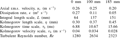
Table 1 shows the turbulent characteristics of the gas flow at the measurement locations $R=0$
, 100 and 185 mm. For any measurement location, the integral length scale (
$R=0$
, 100 and 185 mm. For any measurement location, the integral length scale ( $L$
) of the gas flow turbulence is obtained from the two-point axial velocity correlation coefficient (
$L$
) of the gas flow turbulence is obtained from the two-point axial velocity correlation coefficient ( $R_{u_{g}u_{g}}$
) as reported in our paper (Sahu et al.
Reference Sahu, Hardalupas and Taylor2014). The magnitude of
$R_{u_{g}u_{g}}$
) as reported in our paper (Sahu et al.
Reference Sahu, Hardalupas and Taylor2014). The magnitude of $L$
at
$L$
at $R=0$
mm agrees well with the estimated value as one-fifth of the spray radius
$R=0$
mm agrees well with the estimated value as one-fifth of the spray radius ${\approx}50$
mm (Kavounides Reference Kavounides2006). The characteristic time scale of the entrained air flow by the spray (
${\approx}50$
mm (Kavounides Reference Kavounides2006). The characteristic time scale of the entrained air flow by the spray ( ${\it\tau}_{g}$
) is chosen as the ratio of the integral length scale to the axial r.m.s. velocity of the air flow (
${\it\tau}_{g}$
) is chosen as the ratio of the integral length scale to the axial r.m.s. velocity of the air flow ( $u_{gr}$
). In order to examine the response of the droplets to the smallest motion of the flow, the magnitude of the Kolmogorov length and time scales (
$u_{gr}$
). In order to examine the response of the droplets to the smallest motion of the flow, the magnitude of the Kolmogorov length and time scales ( ${\it\eta}$
and
${\it\eta}$
and ${\it\tau}_{k}$
) should be known. Hence,
${\it\tau}_{k}$
) should be known. Hence, ${\it\eta}$
and
${\it\eta}$
and ${\it\tau}_{k}$
were calculated via dissipation rate (
${\it\tau}_{k}$
were calculated via dissipation rate ( ${\it\epsilon}$
), which in turn was estimated by the dimensional analysis (Tennekes & Lumley Reference Tennekes and Lumley1972), according to which
${\it\epsilon}$
), which in turn was estimated by the dimensional analysis (Tennekes & Lumley Reference Tennekes and Lumley1972), according to which ${\it\epsilon}=u_{gr}^{3}/L$
. The Kolmogorov length and time scales at
${\it\epsilon}=u_{gr}^{3}/L$
. The Kolmogorov length and time scales at $R=0$
mm location, were of the order of
$R=0$
mm location, were of the order of $300~{\rm\mu}\text{m}$
and 6 ms, respectively. The turbulent Reynolds number of the gas flow, calculated based on the integral length scale (
$300~{\rm\mu}\text{m}$
and 6 ms, respectively. The turbulent Reynolds number of the gas flow, calculated based on the integral length scale ( $Re={\it\rho}_{g}u_{gr}L/{\it\mu}_{g}$
,
$Re={\it\rho}_{g}u_{gr}L/{\it\mu}_{g}$
, ${\it\rho}_{g}$
is the density of the fluid), was 1280 for the location
${\it\rho}_{g}$
is the density of the fluid), was 1280 for the location $R=0$
mm. It can be observed in table 1 that the turbulent length and time scales increase away from the spray centre, and this results in reduction in droplet Stokes number of the considered size classes.
$R=0$
mm. It can be observed in table 1 that the turbulent length and time scales increase away from the spray centre, and this results in reduction in droplet Stokes number of the considered size classes.
Turbulent characteristics of the flow at the measurement locations $R=0$
, 100 and 185 mm.
$R=0$
, 100 and 185 mm.
We emphasize that although the spatial resolution of our PIV measurement is of the order of the Kolmogorov length scale, it is not good enough to obtain the Taylor length scale through parabolic fitting of the $R_{u_{g}u_{g}}$
curve at the ‘zero lag’ (
$R_{u_{g}u_{g}}$
curve at the ‘zero lag’ ( ${\it\delta}x=0$
). This is evident from the fact that the gradient of
${\it\delta}x=0$
). This is evident from the fact that the gradient of $R_{u_{g}u_{g}}$
at
$R_{u_{g}u_{g}}$
at ${\it\delta}x=0$
is negative (see figure 15; Sahu et al.
Reference Sahu, Hardalupas and Taylor2014), which should be zero ideally. Hence, this approach would not be suitable. The other approach to estimate
${\it\delta}x=0$
is negative (see figure 15; Sahu et al.
Reference Sahu, Hardalupas and Taylor2014), which should be zero ideally. Hence, this approach would not be suitable. The other approach to estimate ${\it\lambda}$
from the dissipation rate (
${\it\lambda}$
from the dissipation rate ( ${\it\epsilon}$
), which is obtained based on the velocity derivatives such that
${\it\epsilon}$
), which is obtained based on the velocity derivatives such that ${\it\epsilon}=15~{\it\mu}_{g}\overline{(\partial u/\partial x)^{2}}{\it\rho}_{g}$
. However, this approach is sensitive to the numerical scheme used to evaluate the velocity derivative. It always leads to overestimation of
${\it\epsilon}=15~{\it\mu}_{g}\overline{(\partial u/\partial x)^{2}}{\it\rho}_{g}$
. However, this approach is sensitive to the numerical scheme used to evaluate the velocity derivative. It always leads to overestimation of ${\it\epsilon}$
due to the error in derivative approximations by finite differences and for the spatial filtering of PIV data (de Jong et al.
Reference de Jong, Cao, Woodward, Salazar, Collins and Meng2009). Moreover, in our case PIV images are ‘non-ideal’, since the images contain ‘holes’ after droplet filtering. In such cases, the calculation of velocity derivatives, especially close to droplet position, will be erroneous. Hence, we rely on estimating the turbulent quantities using the scaling arguments in an order of magnitude sense only.
${\it\epsilon}$
due to the error in derivative approximations by finite differences and for the spatial filtering of PIV data (de Jong et al.
Reference de Jong, Cao, Woodward, Salazar, Collins and Meng2009). Moreover, in our case PIV images are ‘non-ideal’, since the images contain ‘holes’ after droplet filtering. In such cases, the calculation of velocity derivatives, especially close to droplet position, will be erroneous. Hence, we rely on estimating the turbulent quantities using the scaling arguments in an order of magnitude sense only.
Probability of droplet size in the measurement region at the cross-stream location (a) $R=0$
mm (
$R=0$
mm ( $\text{AMD}=36.4~{\rm\mu}\text{m}$
,
$\text{AMD}=36.4~{\rm\mu}\text{m}$
, $\text{SMD}=48.5~{\rm\mu}\text{m}$
), (b)
$\text{SMD}=48.5~{\rm\mu}\text{m}$
), (b) $R=100$
mm (
$R=100$
mm ( $\text{AMD}=34.4~{\rm\mu}\text{m}$
,
$\text{AMD}=34.4~{\rm\mu}\text{m}$
, $\text{SMD}=45.2~{\rm\mu}\text{m}$
), (c)
$\text{SMD}=45.2~{\rm\mu}\text{m}$
), (c) $R=185$
mm (
$R=185$
mm ( $\text{AMD}=33.0~{\rm\mu}\text{m}$
,
$\text{AMD}=33.0~{\rm\mu}\text{m}$
, $\text{SMD}=43.1~{\rm\mu}\text{m}$
).
$\text{SMD}=43.1~{\rm\mu}\text{m}$
).

3.1 Droplet size distribution in the spray
The probability of the measured droplet size distribution (from ILIDS) is shown in figure 3 for the measurement locations at $R=0$
mm, 100 mm and 185 mm respectively. The minimum measurable droplet size was
$R=0$
mm, 100 mm and 185 mm respectively. The minimum measurable droplet size was $20~{\rm\mu}\text{m}$
as determined by the limitations in the optical set-up and ILIDS image processing, Sahu (Reference Sahu2011). The size distributions show that most droplets are in the range of 20–
$20~{\rm\mu}\text{m}$
as determined by the limitations in the optical set-up and ILIDS image processing, Sahu (Reference Sahu2011). The size distributions show that most droplets are in the range of 20– $40~{\rm\mu}\text{m}$
. It can be also observed that away from the axis of the spray, the probability of small droplets (20–
$40~{\rm\mu}\text{m}$
. It can be also observed that away from the axis of the spray, the probability of small droplets (20– $30~{\rm\mu}\text{m}$
) increases slightly while that of the larger droplets (
$30~{\rm\mu}\text{m}$
) increases slightly while that of the larger droplets ( ${>}50~{\rm\mu}\text{m}$
) decreases, although the change is small. Thus, away from the central spray region, the arithmetic mean diameter (AMD) and SMD of the drop size distribution decreases slightly. However, considering the accuracy of the droplet size measurement for the present case (
${>}50~{\rm\mu}\text{m}$
) decreases, although the change is small. Thus, away from the central spray region, the arithmetic mean diameter (AMD) and SMD of the drop size distribution decreases slightly. However, considering the accuracy of the droplet size measurement for the present case ( $\pm 3.25~{\rm\mu}\text{m}$
), the AMD and SMD of the drop size distribution at any measurement location can be considered to be of the order of
$\pm 3.25~{\rm\mu}\text{m}$
), the AMD and SMD of the drop size distribution at any measurement location can be considered to be of the order of $35~{\rm\mu}\text{m}$
and
$35~{\rm\mu}\text{m}$
and $45~{\rm\mu}\text{m}$
, respectively. All the statistical quantities of the spray were calculated for three droplet size classes (denoted by notation ‘
$45~{\rm\mu}\text{m}$
, respectively. All the statistical quantities of the spray were calculated for three droplet size classes (denoted by notation ‘ $D$
’). The size classes were 20–
$D$
’). The size classes were 20– $35~{\rm\mu}\text{m}$
, 35–
$35~{\rm\mu}\text{m}$
, 35– $50~{\rm\mu}\text{m}$
and 50–
$50~{\rm\mu}\text{m}$
and 50– $65~{\rm\mu}\text{m}$
respectively. The size width (
$65~{\rm\mu}\text{m}$
respectively. The size width ( ${\rm\Delta}D$
) of
${\rm\Delta}D$
) of $15~{\rm\mu}\text{m}$
for each size class was selected as a compromise between higher statistical uncertainty (with smaller
$15~{\rm\mu}\text{m}$
for each size class was selected as a compromise between higher statistical uncertainty (with smaller ${\rm\Delta}D$
) and obtaining size-averaged information (with larger
${\rm\Delta}D$
) and obtaining size-averaged information (with larger ${\rm\Delta}D$
).
${\rm\Delta}D$
).
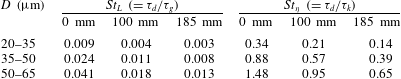
Droplet Stokes number of various size classes based on integral scale, $St_{L}$
(
$St_{L}$
( $=\,{\it\tau}_{d}/{\it\tau}_{g}$
) and Kolmogorov scale,
$=\,{\it\tau}_{d}/{\it\tau}_{g}$
) and Kolmogorov scale, $St_{{\it\eta}}$
(
$St_{{\it\eta}}$
( $=\,{\it\tau}_{d}/{\it\tau}_{k}$
) for the cross-stream measurement locations,
$=\,{\it\tau}_{d}/{\it\tau}_{k}$
) for the cross-stream measurement locations, $R=0$
mm, 100 mm and 185 mm, respectively.
$R=0$
mm, 100 mm and 185 mm, respectively.
The Stokes number ( $St$
) of a droplet size class is defined as the ratio of the droplet aerodynamic time constant or the ‘droplet relaxation time’ (
$St$
) of a droplet size class is defined as the ratio of the droplet aerodynamic time constant or the ‘droplet relaxation time’ ( ${\it\tau}_{d}$
) over an appropriate turbulent time scale of the flow.
${\it\tau}_{d}$
) over an appropriate turbulent time scale of the flow. ${\it\tau}_{d}$
is obtained based on the assumption of Stokes flow around the droplet, which is justified since the Reynolds number of the droplets based on mean slip velocity was very small in the present case (
${\it\tau}_{d}$
is obtained based on the assumption of Stokes flow around the droplet, which is justified since the Reynolds number of the droplets based on mean slip velocity was very small in the present case ( ${\approx}0.1$
). The average of maximum and minimum droplet sizes of each size class (for instance
${\approx}0.1$
). The average of maximum and minimum droplet sizes of each size class (for instance $27.5~{\rm\mu}\text{m}$
for 20–
$27.5~{\rm\mu}\text{m}$
for 20– $35~{\rm\mu}\text{m}$
droplet size class) is considered for calculation of
$35~{\rm\mu}\text{m}$
droplet size class) is considered for calculation of ${\it\tau}_{d}$
. Based on the characteristic time of the entrained air flow by the spray, the values of Stokes number, denoted as
${\it\tau}_{d}$
. Based on the characteristic time of the entrained air flow by the spray, the values of Stokes number, denoted as $St_{L}$
(
$St_{L}$
( $={\it\tau}_{d}/{\it\tau}_{g}$
), for the three droplet size classes were calculated for different droplet sizes classes and found to be of the order of 0.01 for different measurement locations (table 2). These values suggest good response of all droplet sizes to the corresponding large-scale fluid motion. The size of all of the droplets in the spray was smaller than the Kolmogorov length scale of the flow. The Stokes numbers based on the Kolmogorov time scale,
$={\it\tau}_{d}/{\it\tau}_{g}$
), for the three droplet size classes were calculated for different droplet sizes classes and found to be of the order of 0.01 for different measurement locations (table 2). These values suggest good response of all droplet sizes to the corresponding large-scale fluid motion. The size of all of the droplets in the spray was smaller than the Kolmogorov length scale of the flow. The Stokes numbers based on the Kolmogorov time scale, $St_{{\it\eta}}$
(
$St_{{\it\eta}}$
( $={\it\tau}_{d}/{\it\tau}_{k}$
), for the 20–
$={\it\tau}_{d}/{\it\tau}_{k}$
), for the 20– $35~{\rm\mu}\text{m}$
, 35–
$35~{\rm\mu}\text{m}$
, 35– $50~{\rm\mu}\text{m}$
and 50–
$50~{\rm\mu}\text{m}$
and 50– $65~{\rm\mu}\text{m}$
droplet size classes were of the order of 0.34, 0.88 and 1.48, respectively for the
$65~{\rm\mu}\text{m}$
droplet size classes were of the order of 0.34, 0.88 and 1.48, respectively for the $R=0$
mm location, which decreases towards the spray edge (see table 2). These values signify partial response of the droplets to the smallest length scale of the flow.
$R=0$
mm location, which decreases towards the spray edge (see table 2). These values signify partial response of the droplets to the smallest length scale of the flow.
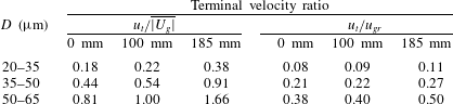
In order to estimate the gravitational influence on the droplet motion in comparison to the inertial effects, the terminal velocity ratio of the droplets is estimated, which is defined as the ratio of terminal velocity of droplets to a characteristic velocity of the gas flow. The terminal velocity, $u_{t}$
(
$u_{t}$
( $={\it\tau}_{d}g$
), were calculated and found to be of the order of 0.02
$={\it\tau}_{d}g$
), were calculated and found to be of the order of 0.02 $\text{m}~\text{s}^{-1}$
,
$\text{m}~\text{s}^{-1}$
, $0.05~\text{m}~\text{s}^{-1}$
and
$0.05~\text{m}~\text{s}^{-1}$
and $0.1~\text{m}~\text{s}^{-1}$
for the three droplet size classes respectively. The terminal velocity ratio based on axial mean gas velocity (
$0.1~\text{m}~\text{s}^{-1}$
for the three droplet size classes respectively. The terminal velocity ratio based on axial mean gas velocity ( $u_{t}/\overline{|U_{g}|}$
), and based on axial gas r.m.s. velocity (
$u_{t}/\overline{|U_{g}|}$
), and based on axial gas r.m.s. velocity ( $u_{t}/u_{gr}$
) for the three droplet size classes are presented in table 3 for the measurement locations at
$u_{t}/u_{gr}$
) for the three droplet size classes are presented in table 3 for the measurement locations at $R=0$
, 100 and 185 mm. Table 3 shows that, except for the smaller droplets (20–
$R=0$
, 100 and 185 mm. Table 3 shows that, except for the smaller droplets (20– $35~{\rm\mu}\text{m}$
), the gravitational influence on the motion of larger droplet size classes cannot be considered negligible, and it increases relative to the inertial effects towards the outer spray region. At
$35~{\rm\mu}\text{m}$
), the gravitational influence on the motion of larger droplet size classes cannot be considered negligible, and it increases relative to the inertial effects towards the outer spray region. At $R=185$
mm, the ratio of
$R=185$
mm, the ratio of $u_{t}$
to the cross-stream gas r.m.s. velocity (
$u_{t}$
to the cross-stream gas r.m.s. velocity ( $v_{gr}$
) for the three droplet size classes are of the order of 0.2, 0.5 and 0.9, which further signifies the important role of gravity at the spray edge.
$v_{gr}$
) for the three droplet size classes are of the order of 0.2, 0.5 and 0.9, which further signifies the important role of gravity at the spray edge.
Terminal velocity ratio of various droplet sizes based on axial mean gas velocity ( $u_{t}/\overline{|U_{g}|}$
) and axial gas r.m.s. velocity (
$u_{t}/\overline{|U_{g}|}$
) and axial gas r.m.s. velocity ( $u_{t}/u_{gr}$
) for the cross-stream measurement locations,
$u_{t}/u_{gr}$
) for the cross-stream measurement locations, $R=0$
mm, 100 mm and 185 mm respectively.
$R=0$
mm, 100 mm and 185 mm respectively.
3.2 Mean flow properties
3.2.1 Droplet and gas velocity
The method of estimating mean and r.m.s. velocity, and the corresponding uncertainties were discussed in detail in Sahu et al. (Reference Sahu, Hardalupas and Taylor2014) and is not repeated here. The mean velocity of droplets of a given size class and the mean gas velocity for both axial and cross-stream velocity components at any measurement location were observed to be quasi-uniform across the measuring area. The corresponding r.m.s. of velocity fluctuations also followed a similar trend. This is possibly because of the small size of the viewing area ( $8\times 12~\text{mm}^{2}$
in the present case), as compared to the length scales of the large eddies of the flow, which were approximately 50 mm. Figure 4(a,b) show the variation of the area-averaged mean and r.m.s. velocity in both axial and cross-stream directions for droplet size class of 20–
$8\times 12~\text{mm}^{2}$
in the present case), as compared to the length scales of the large eddies of the flow, which were approximately 50 mm. Figure 4(a,b) show the variation of the area-averaged mean and r.m.s. velocity in both axial and cross-stream directions for droplet size class of 20– $35~{\rm\mu}\text{m}$
and gas flow for various measurement positions,
$35~{\rm\mu}\text{m}$
and gas flow for various measurement positions, $R$
. The droplets, away from the centre of the spray, tend to move upwards (negative velocity) i.e. ‘towards the top of the spraying tower’. This occurs due to the motion of the entrained air flow in the spray, which has a recirculating flow pattern at the outer region (figure 4
a) in order to conserve mass and momentum, similar to the schematic shown in figure 1(a). Towards the outer spray, the droplets are prevented from drifting downward under the action of gravity, as might be expected, by the upward motion of the gas velocity. This explains the small decrease in the probability of large droplets (
$R$
. The droplets, away from the centre of the spray, tend to move upwards (negative velocity) i.e. ‘towards the top of the spraying tower’. This occurs due to the motion of the entrained air flow in the spray, which has a recirculating flow pattern at the outer region (figure 4
a) in order to conserve mass and momentum, similar to the schematic shown in figure 1(a). Towards the outer spray, the droplets are prevented from drifting downward under the action of gravity, as might be expected, by the upward motion of the gas velocity. This explains the small decrease in the probability of large droplets ( ${>}50~{\rm\mu}\text{m}$
) at
${>}50~{\rm\mu}\text{m}$
) at $R=185$
mm in figure 3.
$R=185$
mm in figure 3.
Area-averaged (a) mean velocity and (b) r.m.s. of velocity fluctuations, for droplet (size class 20– $35~{\rm\mu}\text{m}$
) and gas flow for various cross-stream measurement locations,
$35~{\rm\mu}\text{m}$
) and gas flow for various cross-stream measurement locations, $R$
. Note that the positive mean velocity is at the lower section of the vertical axis in order to demonstrate the flow motion along the direction of gravity.
$R$
. Note that the positive mean velocity is at the lower section of the vertical axis in order to demonstrate the flow motion along the direction of gravity.

The fluctuating velocities of both droplets and gas decreased away from the spray axis implying reduction of the turbulent kinetic energy in the outer spray region (figure 4
b). However, compared to the axial direction, considerable reduction in r.m.s. velocity in the cross-stream direction (approximately 50 %) was observed from $R=0$
to 185 mm. Thus, the flow was nearly isotropic close to the spray centre (the ratio
$R=0$
to 185 mm. Thus, the flow was nearly isotropic close to the spray centre (the ratio $u_{gr}/v_{gr}\approx 1$
at the location
$u_{gr}/v_{gr}\approx 1$
at the location $R=0$
mm). This is further confirmed from the
$R=0$
mm). This is further confirmed from the $x$
-velocity spectra as shown in figure 5, which is obtained by taking Fourier transform of the two-point correlation coefficients of axial gas velocity fluctuations (
$x$
-velocity spectra as shown in figure 5, which is obtained by taking Fourier transform of the two-point correlation coefficients of axial gas velocity fluctuations ( $R_{u_{g}u_{g}}$
). However, as the measurement window dimensions are approximately five to six times smaller than the integral length scale of the turbulent carrier phase flow, so we had to extrapolate
$R_{u_{g}u_{g}}$
). However, as the measurement window dimensions are approximately five to six times smaller than the integral length scale of the turbulent carrier phase flow, so we had to extrapolate $R_{u_{g}u_{g}}$
to ‘zero’ (following Sahu et al.
Reference Sahu, Hardalupas and Taylor2014). Since nearly 90 % of the overall data is contributed by the extrapolated exponential curve fit, the resulting length scale is sensitive to the fitting parameters and any error they contain. Hence, the spectral data seems to be free from uncertainty and the wavenumbers span a large range. However, we observed a basic agreement between the calculated integral length scale (as derived from the area under the extrapolated
$R_{u_{g}u_{g}}$
to ‘zero’ (following Sahu et al.
Reference Sahu, Hardalupas and Taylor2014). Since nearly 90 % of the overall data is contributed by the extrapolated exponential curve fit, the resulting length scale is sensitive to the fitting parameters and any error they contain. Hence, the spectral data seems to be free from uncertainty and the wavenumbers span a large range. However, we observed a basic agreement between the calculated integral length scale (as derived from the area under the extrapolated $R_{u_{g}u_{g}}$
curve, denoted as, effective length scale
$R_{u_{g}u_{g}}$
curve, denoted as, effective length scale $L_{eff}$
) and the estimated value of
$L_{eff}$
) and the estimated value of $L$
(
$L$
( ${\sim}50$
mm, as mentioned earlier). The calculated
${\sim}50$
mm, as mentioned earlier). The calculated $L_{eff}$
was approximately 65 mm, which is close to
$L_{eff}$
was approximately 65 mm, which is close to $L$
. Thus, the extrapolation procedure has some basis, at least as a first approximation. Figure 5 indicates isotropic turbulence is established for the location
$L$
. Thus, the extrapolation procedure has some basis, at least as a first approximation. Figure 5 indicates isotropic turbulence is established for the location $R=0$
mm, while the anisotropy increases towards the edge of the spray (
$R=0$
mm, while the anisotropy increases towards the edge of the spray ( $u_{gr}/v_{gr}\approx 1.8$
for the location
$u_{gr}/v_{gr}\approx 1.8$
for the location $R=185$
mm).
$R=185$
mm).
One-dimensional axial velocity spectra ( $E_{uu}$
) with respect to different wavenumbers
$E_{uu}$
) with respect to different wavenumbers $k_{u}=2{\rm\pi}/{\it\delta}x$
for the measurement locations
$k_{u}=2{\rm\pi}/{\it\delta}x$
for the measurement locations $R=0$
, 100, 185 mm. The straight line represents the model spectra according to
$R=0$
, 100, 185 mm. The straight line represents the model spectra according to $E_{uu}\propto k_{u}^{-5/3}$
.
$E_{uu}\propto k_{u}^{-5/3}$
.

In our experiments, at any measurement location, the r.m.s. of the velocity fluctuations in the axial direction was about two times larger than the mean velocity (figure 4). Similar observations in the trends of mean and r.m.s. velocities have been reported by Risso & Fabre (Reference Risso and Fabre1997) in their single phase turbulence measurements of a confined axisymmetric water jet far from the nozzle. These features are typical to the confined flow systems and have been also reported by Boree, Ishima & Flour (Reference Boree, Ishima and Flour2001). In our measurement locations, since the mean velocity and its gradients in both directions were small, it is also expected that there is negligible turbulence production due to the shear layer. This is confirmed by low values of normalized Reynolds stress ( $\overline{u_{g}v_{g}}/{u_{r}}^{2}<0.2$
) obtained at different measurement locations (see figure 9 in Sahu et al. (Reference Sahu, Hardalupas and Taylor2014)). We reported the two-point spatial correlation coefficient between droplet–gas, and gas velocity fluctuations (
$\overline{u_{g}v_{g}}/{u_{r}}^{2}<0.2$
) obtained at different measurement locations (see figure 9 in Sahu et al. (Reference Sahu, Hardalupas and Taylor2014)). We reported the two-point spatial correlation coefficient between droplet–gas, and gas velocity fluctuations ( $R_{dg}$
and
$R_{dg}$
and $R_{gg}$
, respectively) for different velocity components and also measurement locations (figure 12; Sahu et al. (Reference Sahu, Hardalupas and Taylor2014)). The spatial evolution of
$R_{gg}$
, respectively) for different velocity components and also measurement locations (figure 12; Sahu et al. (Reference Sahu, Hardalupas and Taylor2014)). The spatial evolution of $R_{gg}$
at all measurement locations implied strong correlation of the gas velocity field with itself (
$R_{gg}$
at all measurement locations implied strong correlation of the gas velocity field with itself ( $R_{u_{g}u_{g}}>0.8$
and
$R_{u_{g}u_{g}}>0.8$
and $R_{v_{g}v_{g}}$ ${>}0.6$
). The magnitude of
${>}0.6$
). The magnitude of $R_{gg}$
for both axial and cross-stream velocity remained nearly constant for different lags since the measurement window size is about an order of magnitude smaller than the large-scale eddies. In addition, for all measurement locations our proper orthogonal decomposition (POD) analysis of the gas velocity (see figures 16 and 17 in Sahu et al. (Reference Sahu, Hardalupas and Taylor2014)) signified the dominance of large-scale eddies in the flow dynamics (first three POD modes contributes about 50 % of total TKE of the gas flow). We find that the spatial correlation between droplet and gas axial velocity is also high (the normalized droplet–gas velocity correlation,
$R_{gg}$
for both axial and cross-stream velocity remained nearly constant for different lags since the measurement window size is about an order of magnitude smaller than the large-scale eddies. In addition, for all measurement locations our proper orthogonal decomposition (POD) analysis of the gas velocity (see figures 16 and 17 in Sahu et al. (Reference Sahu, Hardalupas and Taylor2014)) signified the dominance of large-scale eddies in the flow dynamics (first three POD modes contributes about 50 % of total TKE of the gas flow). We find that the spatial correlation between droplet and gas axial velocity is also high (the normalized droplet–gas velocity correlation, $\overline{u_{d}u_{g}}/u_{dr}u_{gr}>0.8$
), and the first POD mode is solely responsible for the strong coupling between droplet and gas phase velocity in axial direction, while contribution of other modes are negligible. This suggests that the fluctuating motion, not the mean velocity, plays a central role in the two phase flow dynamics in the considered measurement locations within the spray.
$\overline{u_{d}u_{g}}/u_{dr}u_{gr}>0.8$
), and the first POD mode is solely responsible for the strong coupling between droplet and gas phase velocity in axial direction, while contribution of other modes are negligible. This suggests that the fluctuating motion, not the mean velocity, plays a central role in the two phase flow dynamics in the considered measurement locations within the spray.
3.2.2 Droplet concentration
The normalized mean and r.m.s. of the droplet concentration are plotted in figure 6 for the three drop size classes. Normalization was based on the corresponding mean values at $R=0$
mm. Away from the spray axis, the mean droplet concentration of the smallest droplet size class of 20–
$R=0$
mm. Away from the spray axis, the mean droplet concentration of the smallest droplet size class of 20– $35~{\rm\mu}\text{m}$
remains approximately constant, while that of larger size classes decrease. Also, considering the mean velocity of the entrained gas flow (figure 4
a), which implies the presence of a vortical pattern of the mean gas flow, it can be argued that further away from the spray axis, the small droplets (having good response to the integral scale of the flow and negligible gravitational effects) are carried easily towards the top of the tower. This results in their uniform distribution across the spray and smaller fluctuations of droplet concentration (about 30 %) compared to the mean (figure 6
b). Thus, the concentration of smaller droplets is mainly controlled by the convective fluid motion. Due to their partial response to the gas flow and the higher gravitational influence (table 3), the larger droplets resist the upward motion of the gas flow. Hence the corresponding mean droplet concentration consistently decreases towards the spray edge, and no additional influence of the shear layer at
$35~{\rm\mu}\text{m}$
remains approximately constant, while that of larger size classes decrease. Also, considering the mean velocity of the entrained gas flow (figure 4
a), which implies the presence of a vortical pattern of the mean gas flow, it can be argued that further away from the spray axis, the small droplets (having good response to the integral scale of the flow and negligible gravitational effects) are carried easily towards the top of the tower. This results in their uniform distribution across the spray and smaller fluctuations of droplet concentration (about 30 %) compared to the mean (figure 6
b). Thus, the concentration of smaller droplets is mainly controlled by the convective fluid motion. Due to their partial response to the gas flow and the higher gravitational influence (table 3), the larger droplets resist the upward motion of the gas flow. Hence the corresponding mean droplet concentration consistently decreases towards the spray edge, and no additional influence of the shear layer at $R=100$
mm location is observed. Though more measurements at additional cross-stream locations would strengthen our argument but we believe that our results provide enough evidence to support the arguments for the suggested observations. The larger droplets show larger relative fluctuations of drop concentration (
$R=100$
mm location is observed. Though more measurements at additional cross-stream locations would strengthen our argument but we believe that our results provide enough evidence to support the arguments for the suggested observations. The larger droplets show larger relative fluctuations of drop concentration ( ${\approx}50\,\%$
of the respective mean) compared to the 20–
${\approx}50\,\%$
of the respective mean) compared to the 20– $35~{\rm\mu}\text{m}$
droplets, which can be attributed to preferential concentration of the large droplets due to their partial response to fluid flow turbulence (i.e.
$35~{\rm\mu}\text{m}$
droplets, which can be attributed to preferential concentration of the large droplets due to their partial response to fluid flow turbulence (i.e. $St_{{\it\eta}}\approx 1$
) as described in the following section.
$St_{{\it\eta}}\approx 1$
) as described in the following section.
Normalized (a) mean droplet concentration and (b) r.m.s. of droplet concentration fluctuations for the three droplet size classes for various cross-stream measurement locations, $R$
. Normalization was based on the respective mean value at
$R$
. Normalization was based on the respective mean value at $R=0$
mm.
$R=0$
mm.

4 Influence of gas flow turbulence on droplet concentration
It is known that in a particle-laden flow, the semiorganized or coherent structures in turbulence may disperse particles in an organized manner (Lazaro & Lasheras Reference Lazaro and Lasheras1992; Longmire & Eaton Reference Longmire and Eaton1992) and are likely to produce instantaneous concentration fluctuations even if the particles are initially uniformly distributed. Particles with $St$
(based on Kolmogorov time scale) of the order of ‘one’ tend to disperse away from vortex cores of the flow and, in many cases, collect in regions surrounding the vortices (Wang & Maxey Reference Wang and Maxey1993; Fessler et al.
Reference Fessler, Kulick and Eaton1994; Wood et al.
Reference Wood, Hwang and Eaton2005). Eaton & Fessler (Reference Eaton and Fessler1994) have reviewed the experimental and numerical studies, which demonstrate this phenomenon of preferential concentration in a wide variety of flows. In their recent review, Monchaux, Bourgoin & Cartellier (Reference Monchaux, Bourgoin and Cartellier2012) summarized the different techniques available to quantitatively investigate the preferential concentration and clustering. The present section evaluates the presence of preferential concentration of droplets in a spray using two independent approaches, and estimates the dimensions of droplet clusters conditional on droplet size for the first time. The link between fluctuations of droplet concentration and velocity of both phases is also established, for the first time, conditional on droplet size, by calculating the corresponding correlation coefficients.
$St$
(based on Kolmogorov time scale) of the order of ‘one’ tend to disperse away from vortex cores of the flow and, in many cases, collect in regions surrounding the vortices (Wang & Maxey Reference Wang and Maxey1993; Fessler et al.
Reference Fessler, Kulick and Eaton1994; Wood et al.
Reference Wood, Hwang and Eaton2005). Eaton & Fessler (Reference Eaton and Fessler1994) have reviewed the experimental and numerical studies, which demonstrate this phenomenon of preferential concentration in a wide variety of flows. In their recent review, Monchaux, Bourgoin & Cartellier (Reference Monchaux, Bourgoin and Cartellier2012) summarized the different techniques available to quantitatively investigate the preferential concentration and clustering. The present section evaluates the presence of preferential concentration of droplets in a spray using two independent approaches, and estimates the dimensions of droplet clusters conditional on droplet size for the first time. The link between fluctuations of droplet concentration and velocity of both phases is also established, for the first time, conditional on droplet size, by calculating the corresponding correlation coefficients.
4.1 Scale of droplet clustering
4.1.1 The ‘droplet counting in a cell’ approach
In order to obtain the characteristic dimensions of droplet clusters in the flow, the probability density function (PDF) of the local concentration is compared with that arising from a purely random process (Fessler et al.
Reference Fessler, Kulick and Eaton1994; Aliseda et al.
Reference Aliseda, Cartellier, Hainaux and Lasheras2002). For this purpose, at first, the instantaneous droplet concentration was obtained from the two-dimensional focused (PIV) images of the flow at the different measurement locations. However, the droplet sizing technique (ILIDS) was not used for this purpose because it is not possible to identify all droplets appearing on the ILIDS image due to the imposed image processing criteria. At any given instant, the PDF of the droplet concentration was obtained by dividing an image into cells of a certain size and counting the number of droplets inside each cell. If $C$
is the total number of detected droplets and
$C$
is the total number of detected droplets and $N_{b}$
is the total number of cells, then the probability of finding
$N_{b}$
is the total number of cells, then the probability of finding $n$
droplets per cell is obtained as the ratio of the sum of the number of droplets in the cells containing ‘
$n$
droplets per cell is obtained as the ratio of the sum of the number of droplets in the cells containing ‘ $n$
’ droplets and the total number of droplets in all of the cells (
$n$
’ droplets and the total number of droplets in all of the cells ( $C$
). The PDF averaged over all images was obtained and compared with the distribution of droplets in cells for a random process, given by a binomial distribution:
$C$
). The PDF averaged over all images was obtained and compared with the distribution of droplets in cells for a random process, given by a binomial distribution:
 $$\begin{eqnarray}\displaystyle P_{binomial}(n)=\binom{\bar{C}}{n}\left(\frac{1}{N_{b}}\right)^{n}\left(1-\frac{1}{N_{b}}\right)^{\bar{C}-n}, & & \displaystyle\end{eqnarray}$$
where $\bar{C}$
is the mean number of detected droplets (averaged over all sample images). The comparison between the PDF found for a given cell size and that for a random process provides an indication of how turbulence modifies the droplet concentration field.
$\bar{C}$
is the mean number of detected droplets (averaged over all sample images). The comparison between the PDF found for a given cell size and that for a random process provides an indication of how turbulence modifies the droplet concentration field.
Comparison of PDF of the measured number of droplets per cell with a binomial distribution, representing a random process, for the cross-stream measurement location at $R=0$
mm for six different box sizes with dimensions (a)
$R=0$
mm for six different box sizes with dimensions (a) $1~\text{mm}\times 1~\text{mm}$
, (b)
$1~\text{mm}\times 1~\text{mm}$
, (b) $2~\text{mm}\times 2~\text{mm}$
, (c)
$2~\text{mm}\times 2~\text{mm}$
, (c) $4~\text{mm}\times 4~\text{mm}$
, (d)
$4~\text{mm}\times 4~\text{mm}$
, (d) $4~\text{mm}\times 6~\text{mm}$
, (e)
$4~\text{mm}\times 6~\text{mm}$
, (e) $8~\text{mm}\times 6~\text{mm}$
and (f)
$8~\text{mm}\times 6~\text{mm}$
and (f) $4~\text{mm}\times 12~\text{mm}$
, while the measurement area is
$4~\text{mm}\times 12~\text{mm}$
, while the measurement area is $8~\text{mm}\times 12~\text{mm}$
.
$8~\text{mm}\times 12~\text{mm}$
.

The length scale at which preferential concentration is most effective can be identified by computing these statistics for cells of different sizes. Figure 7 shows the PDF comparison for different cell sizes. Considering the horizontal and vertical dimensions of the measurement area ( $=8~\text{mm}\times 12~\text{mm}$
), sizes of cells were chosen to be approximately
$=8~\text{mm}\times 12~\text{mm}$
), sizes of cells were chosen to be approximately $1~\text{mm}\times 1~\text{mm}$
,
$1~\text{mm}\times 1~\text{mm}$
, $2~\text{mm}\times 2~\text{mm}$
,
$2~\text{mm}\times 2~\text{mm}$
, $4~\text{mm}\times 4~\text{mm}$
,
$4~\text{mm}\times 4~\text{mm}$
, $4~\text{mm}\times 6~\text{mm}$
,
$4~\text{mm}\times 6~\text{mm}$
, $8~\text{mm}\times 6~\text{mm}$
and
$8~\text{mm}\times 6~\text{mm}$
and $4~\text{mm}\times 12~\text{mm}$
, respectively, while larger cell sizes were considered to avoid cell overlapping. It can be observed from figure 7 that for the larger boxes, the PDF of the number of droplets per cell substantially deviates from the corresponding random distribution. This indicates that the length scale of droplet clusters is at least of the order of the dimensions of the measurement area.
$4~\text{mm}\times 12~\text{mm}$
, respectively, while larger cell sizes were considered to avoid cell overlapping. It can be observed from figure 7 that for the larger boxes, the PDF of the number of droplets per cell substantially deviates from the corresponding random distribution. This indicates that the length scale of droplet clusters is at least of the order of the dimensions of the measurement area.
In order to quantify the deviation of the measured PDF of droplet number density from the random distribution two parameters were used. The first one, $D_{1}$
, was introduced by Fessler et al. (Reference Fessler, Kulick and Eaton1994), and is the difference between the standard deviation of the two distributions (
$D_{1}$
, was introduced by Fessler et al. (Reference Fessler, Kulick and Eaton1994), and is the difference between the standard deviation of the two distributions ( ${\it\sigma}$
and
${\it\sigma}$
and ${\it\sigma}_{binomial}$
):
${\it\sigma}_{binomial}$
):
 $$\begin{eqnarray}\displaystyle D_{1}=\frac{{\it\sigma}-{\it\sigma}_{binomial}}{{\it\mu}}, & & \displaystyle\end{eqnarray}$$
where ${\it\mu}$
is the mean number of particles per cell. Positive values of this parameter indicate the presence of concentrated regions, while zero values represent a quasi-uniform concentration field. The second parameter,
${\it\mu}$
is the mean number of particles per cell. Positive values of this parameter indicate the presence of concentrated regions, while zero values represent a quasi-uniform concentration field. The second parameter, $D_{2}$
, was used by Wang & Maxey (Reference Wang and Maxey1993) which represents the square of the difference of probabilities given by the two distributions, and is always positive or zero:
$D_{2}$
, was used by Wang & Maxey (Reference Wang and Maxey1993) which represents the square of the difference of probabilities given by the two distributions, and is always positive or zero:
 $$\begin{eqnarray}\displaystyle D_{2}=\mathop{\sum }_{1}^{C}(P(n)-P_{binom}(n))^{2}. & & \displaystyle\end{eqnarray}$$
The parameters $D_{1}$
and
$D_{1}$
and $D_{2}$
for the different cell sizes corresponding to figure 7.
$D_{2}$
for the different cell sizes corresponding to figure 7.
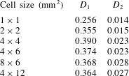
The variation in $D_{1}$
for the cell size of
$D_{1}$
for the cell size of $4~\text{mm}\times 4~\text{mm}$
at different measurement locations,
$4~\text{mm}\times 4~\text{mm}$
at different measurement locations, $R$
. The error bar indicates the uncertainty in
$R$
. The error bar indicates the uncertainty in $D_{1}$
with 95 % confidence interval.
$D_{1}$
with 95 % confidence interval.

In the present case the values of $D_{1}$
and
$D_{1}$
and $D_{2}$
were calculated for the different cell sizes and are presented in table 4. As expected from figure 7, both values increase initially with the cell size and then decreases afterwards. Considering that the statistical uncertainty for
$D_{2}$
were calculated for the different cell sizes and are presented in table 4. As expected from figure 7, both values increase initially with the cell size and then decreases afterwards. Considering that the statistical uncertainty for $D_{2}$
was higher (approximately
$D_{2}$
was higher (approximately $\pm 25\,\%$
compared to
$\pm 25\,\%$
compared to $\pm 5\,\%$
for
$\pm 5\,\%$
for $D_{1}$
), the cell size for which
$D_{1}$
), the cell size for which $D_{1}$
is maximum i.e.
$D_{1}$
is maximum i.e. $4~\text{mm}\times 4~\text{mm}$
is considered to correspond to the order of length scale of droplet clusters. Similar results were observed for other measurement locations. Figure 8 shows the evolution of
$4~\text{mm}\times 4~\text{mm}$
is considered to correspond to the order of length scale of droplet clusters. Similar results were observed for other measurement locations. Figure 8 shows the evolution of $D_{1}$
for the cell size of
$D_{1}$
for the cell size of $4~\text{mm}\times 4~\text{mm}$
at various measurement locations.
$4~\text{mm}\times 4~\text{mm}$
at various measurement locations. $D_{1}$
appears to increase with cross-stream distance
$D_{1}$
appears to increase with cross-stream distance $R$
implying greater tendency of droplets to form clusters near the spray edge compared to the central spray region. Again due to larger statistical uncertainty for
$R$
implying greater tendency of droplets to form clusters near the spray edge compared to the central spray region. Again due to larger statistical uncertainty for $D_{2}$
, comparison between the corresponding values at different measurement locations could not be made.
$D_{2}$
, comparison between the corresponding values at different measurement locations could not be made.
The values of $D_{1}$
for the cell size of 4 mm (
$D_{1}$
for the cell size of 4 mm ( ${\approx}13{\it\eta}$
,
${\approx}13{\it\eta}$
, ${\it\eta}$
is the Kolmogorov length scale of the gas flow) are comparable to the maximum value of
${\it\eta}$
is the Kolmogorov length scale of the gas flow) are comparable to the maximum value of $D_{1}$
for monosized particle laden air flow in a channel as reported by Fessler et al. (Reference Fessler, Kulick and Eaton1994) for
$D_{1}$
for monosized particle laden air flow in a channel as reported by Fessler et al. (Reference Fessler, Kulick and Eaton1994) for $St\approx 0.74$
and 2.2. However, Aliseda et al. (Reference Aliseda, Cartellier, Hainaux and Lasheras2002) have reported lower values of
$St\approx 0.74$
and 2.2. However, Aliseda et al. (Reference Aliseda, Cartellier, Hainaux and Lasheras2002) have reported lower values of $D_{1}$
in their experiments with polydispersed droplets. These authors argued that, in case of monodispersed distributions, either all droplets (with
$D_{1}$
in their experiments with polydispersed droplets. These authors argued that, in case of monodispersed distributions, either all droplets (with $St_{{\it\eta}}\approx 1$
) tend to preferentially accumulate or all tend towards a random distribution (when
$St_{{\it\eta}}\approx 1$
) tend to preferentially accumulate or all tend towards a random distribution (when $St_{{\it\eta}}\ll 1$
or
$St_{{\it\eta}}\ll 1$
or $St_{{\it\eta}}\gg 1$
). For the case of polydispersed distributions, droplets with
$St_{{\it\eta}}\gg 1$
). For the case of polydispersed distributions, droplets with $St_{{\it\eta}}\approx 1$
form clusters which entrain droplets of all other size classes. This results in lowering the values of
$St_{{\it\eta}}\approx 1$
form clusters which entrain droplets of all other size classes. This results in lowering the values of $D_{1}$
. However, the droplet size distribution in the experiments by Aliseda et al. (Reference Aliseda, Cartellier, Hainaux and Lasheras2002) was narrow and the smaller droplets (
$D_{1}$
. However, the droplet size distribution in the experiments by Aliseda et al. (Reference Aliseda, Cartellier, Hainaux and Lasheras2002) was narrow and the smaller droplets ( ${\approx}10~{\rm\mu}\text{m}$
) dominated the size distribution with probability of occurrence of nearly 40 %. Also, only few droplets with Stokes number of the order of 1 were present. In the present experimental conditions, the droplet size distribution is broader, and most droplets respond partially to the smallest scales of the gas flow, which justifies larger deviation from random distribution and, therefore, higher values of
${\approx}10~{\rm\mu}\text{m}$
) dominated the size distribution with probability of occurrence of nearly 40 %. Also, only few droplets with Stokes number of the order of 1 were present. In the present experimental conditions, the droplet size distribution is broader, and most droplets respond partially to the smallest scales of the gas flow, which justifies larger deviation from random distribution and, therefore, higher values of $D_{1}$
.
$D_{1}$
.
For a polydispersed spray, the scale of the droplet clustering can vary for droplets of different sizes, which cannot be distinguished by the presented droplet counting method, which considers PIV images (PIV cannot provide droplet size). In order to quantify the influence of droplet size on the length scale of droplet clusters, the estimation of the radial distribution functions (RDF) for each droplet size is essential, and this has not been reported before. From literature, we mention Saw et al. (Reference Saw, Shaw, Ayyalasomayajula, Chuang and Gylfason2008, Reference Saw, Shaw, Salazar and Collins2012b
) who studied a polydispersed spray in wind tunnel using PDA and measured one-dimensional RDF for different droplet size classes in the spray. They adopted a method equivalent to Taylor’s frozen turbulence hypothesis to convert the time series to droplet spatial distribution along the mean flow direction. However, the hypothesis is valid only for very low turbulent intensities ( $u_{gr}/\overline{U_{g}}\ll 1$
), and this approach is certainly not suitable for the present experiments where turbulent fluctuations are about two times the mean velocity (see figure 4).
$u_{gr}/\overline{U_{g}}\ll 1$
), and this approach is certainly not suitable for the present experiments where turbulent fluctuations are about two times the mean velocity (see figure 4).
4.1.2 Radial distribution function (RDF) of droplet concentration
RDF is a statistical measure of droplet clustering (Sundaram & Collins Reference Sundaram and Collins1999, Salazar et al.
Reference Salazar, de Jong, Cao, Woodward, Meng and Collins2008). It is defined as the probability of finding a second droplet at a given separation distance from a reference droplet compared to a case where the droplets are homogeneously distributed. The RDF is computed from a field of $M$
droplets by ‘binning’ the droplet pairs according to their separation distance, and calculating the function
$M$
droplets by ‘binning’ the droplet pairs according to their separation distance, and calculating the function
 $$\begin{eqnarray}\displaystyle \text{RDF}(r_{i})=\frac{N_{i}/{\it\delta}V_{i}}{N/V}, & & \displaystyle\end{eqnarray}$$
where $N_{i}$
is the number of droplet pairs separated by a distance
$N_{i}$
is the number of droplet pairs separated by a distance $r_{i}\pm {\it\delta}r/2$
,
$r_{i}\pm {\it\delta}r/2$
, ${\it\delta}V_{i}$
is the volume of the discrete shell located at
${\it\delta}V_{i}$
is the volume of the discrete shell located at $r_{i}$
,
$r_{i}$
, $N=M(M-1)/2$
is the total number of pairs and
$N=M(M-1)/2$
is the total number of pairs and $V$
is the total volume of the system. Since the present experimental technique is planar, the RDF measurement is restricted to two dimensions only. Thus, in the above equation the discrete volumetric shell is replaced by an annular area with radius
$V$
is the total volume of the system. Since the present experimental technique is planar, the RDF measurement is restricted to two dimensions only. Thus, in the above equation the discrete volumetric shell is replaced by an annular area with radius $r_{i}$
. This method is similar to the estimation of droplet–gas spatial velocity correlation for different radius of separation,
$r_{i}$
. This method is similar to the estimation of droplet–gas spatial velocity correlation for different radius of separation, $r_{i}$
, as explained in figure 10 of Sahu et al. (Reference Sahu, Hardalupas and Taylor2014). The two-dimensional RDF was calculated using the droplet positions obtained from ILIDS images, the advantage being the ability to obtain
$r_{i}$
, as explained in figure 10 of Sahu et al. (Reference Sahu, Hardalupas and Taylor2014). The two-dimensional RDF was calculated using the droplet positions obtained from ILIDS images, the advantage being the ability to obtain $\text{RDF}(r_{i})$
for different size classes. The increment in
$\text{RDF}(r_{i})$
for different size classes. The increment in $r_{i}$
and,
$r_{i}$
and, ${\it\delta}r$
were chosen to be 1 mm and 2 mm respectively as a compromise between losing the spatial resolution and having enough droplets to obtain appropriate statistics. Holtzer & Collins (Reference Holtzer and Collins2002) have identified that the lower-dimensional RDFs attenuate the measured values at separations below a characteristic length of the measurement (in the present case, thickness of the laser sheet
${\it\delta}r$
were chosen to be 1 mm and 2 mm respectively as a compromise between losing the spatial resolution and having enough droplets to obtain appropriate statistics. Holtzer & Collins (Reference Holtzer and Collins2002) have identified that the lower-dimensional RDFs attenuate the measured values at separations below a characteristic length of the measurement (in the present case, thickness of the laser sheet ${\approx}3{\it\eta}$
). However, for the purpose of estimating the cluster dimension (which is expected to be at least an order of magnitude larger than
${\approx}3{\it\eta}$
). However, for the purpose of estimating the cluster dimension (which is expected to be at least an order of magnitude larger than ${\it\eta}$
, see for example, Fessler et al. (Reference Fessler, Kulick and Eaton1994), Aliseda et al. (Reference Aliseda, Cartellier, Hainaux and Lasheras2002), Yang & Shy (Reference Yang and Shy2005)) and relative affinity of droplets of different sizes for preferential accumulation, two-dimensional RDF can be reliably used.
${\it\eta}$
, see for example, Fessler et al. (Reference Fessler, Kulick and Eaton1994), Aliseda et al. (Reference Aliseda, Cartellier, Hainaux and Lasheras2002), Yang & Shy (Reference Yang and Shy2005)) and relative affinity of droplets of different sizes for preferential accumulation, two-dimensional RDF can be reliably used.
Evaluation of RDF for the cross-stream measurement locations at (a) $R=0$
mm (
$R=0$
mm ( ${\it\eta}=0.30$
mm), (b)
${\it\eta}=0.30$
mm), (b) $R=100$
mm (
$R=100$
mm ( ${\it\eta}=0.37$
mm) and (c)
${\it\eta}=0.37$
mm) and (c) $R=185$
mm (
$R=185$
mm ( ${\it\eta}=0.45$
mm) conditional on droplet size.
${\it\eta}=0.45$
mm) conditional on droplet size.

Figure 9 shows the RDF calculated at three different measurement locations $R=0$
, 100 and 185 mm. The RDFs are plotted for different
$R=0$
, 100 and 185 mm. The RDFs are plotted for different $r_{i}$
values normalized with the local Kolmogorov length scale,
$r_{i}$
values normalized with the local Kolmogorov length scale, ${\it\eta}$
, which is larger towards the spray edge (table 2). The values of RDF
${\it\eta}$
, which is larger towards the spray edge (table 2). The values of RDF ${<}1$
indicate the presence of voids in the flow, i.e. the local concentration becomes lower than the average across the total area of the image. For values of
${<}1$
indicate the presence of voids in the flow, i.e. the local concentration becomes lower than the average across the total area of the image. For values of $\text{RDF}>1$
, droplet clustering occurs. Thus, when
$\text{RDF}>1$
, droplet clustering occurs. Thus, when $\text{RDF}=1$
, the droplet distribution is random, and the corresponding radial separation distance between droplets,
$\text{RDF}=1$
, the droplet distribution is random, and the corresponding radial separation distance between droplets, $r_{i}$
, can be considered as statistical description of the length scale of droplet clusters (termed as ‘
$r_{i}$
, can be considered as statistical description of the length scale of droplet clusters (termed as ‘ $L_{c}$
’). Considering the distribution of RDFs of figure 9, the following trends can be observed.
$L_{c}$
’). Considering the distribution of RDFs of figure 9, the following trends can be observed.
A sample PIV image containing droplets without seeding particles. The image also depicts a droplet cluster and the order of the associated length scale.

-
(1) At any measurement location, the length scales of the clusters, i.e. the values of $L_{c}$
, increase for higher droplet size classes, and are approximately 3–6 mm. This is in accordance with the cell size of
$4~\text{mm}\times 4~\text{mm}$
(as evaluated by the droplet counting in cell approach) for which the
$D_{1}$
factor was maximum at all measurement locations. The cluster dimensions in the present case are approximately
$5{\it\eta}$
–
$15{\it\eta}$
compared to
$10{\it\eta}$
in cases of both Fessler et al. (Reference Fessler, Kulick and Eaton1994) and Aliseda et al. (Reference Aliseda, Cartellier, Hainaux and Lasheras2002). Hence, similar to both of the previous studies, in the present experiments the size of the droplet clusters are expected to be mostly influenced by the viscous effects (at smallest scale) rather than inertial effects (at large scales). A sample PIV image containing droplets without seeding particles is shown in figure 10, which also includes a schematic of a droplet cluster and its associated length scale. The original PIV image was not shown as it contains droplets as well as seeding particles, and so visual evidence of preferential accumulation of droplets is difficult.
$L_{c}$
, increase for higher droplet size classes, and are approximately 3–6 mm. This is in accordance with the cell size of
$4~\text{mm}\times 4~\text{mm}$
(as evaluated by the droplet counting in cell approach) for which the
$D_{1}$
factor was maximum at all measurement locations. The cluster dimensions in the present case are approximately
$5{\it\eta}$
–
$15{\it\eta}$
compared to
$10{\it\eta}$
in cases of both Fessler et al. (Reference Fessler, Kulick and Eaton1994) and Aliseda et al. (Reference Aliseda, Cartellier, Hainaux and Lasheras2002). Hence, similar to both of the previous studies, in the present experiments the size of the droplet clusters are expected to be mostly influenced by the viscous effects (at smallest scale) rather than inertial effects (at large scales). A sample PIV image containing droplets without seeding particles is shown in figure 10, which also includes a schematic of a droplet cluster and its associated length scale. The original PIV image was not shown as it contains droplets as well as seeding particles, and so visual evidence of preferential accumulation of droplets is difficult. -
(2) At any measurement location
$R$
and for any radius of separation
$r_{i}$
, RDF increases for larger droplet size classes, i.e. with increasing
$St_{{\it\eta}}$
of the droplets. So more clustering is evident for 50–
$65~{\rm\mu}\text{m}$
droplets, which correspond to
$St_{{\it\eta}}$
of the order of 1. Saw et al. (Reference Saw, Shaw, Ayyalasomayajula, Chuang and Gylfason2008) have also shown increased peak value of RDF with increasing
$St_{{\it\eta}}$
. However, the present results are in contrast to Wood et al. (Reference Wood, Hwang and Eaton2005), who measured the two-dimensional RDF for monosized particles in homogeneous and isotropic turbulence within a box. These authors found nearly overlapping RDFs for particles with Kolmogorov Stokes number of the order of one (
$St_{{\it\eta}}=0.57$
, 1.06 and 1.33). However, unlike Wood et al. (Reference Wood, Hwang and Eaton2005), gravitational influence on droplets cannot be considered as negligible in our experiments (see table 3). Since, in the present case, clustering is observed at dissipative scales and the Kolmogorov time scale is of similar order as the time required for droplets to fall over a distance
${\it\eta}$
with terminal velocity (
${\it\tau}_{k}\approx {\it\eta}/u_{t}$
), gravity plays a role in clustering and is expected to enhance the preferential accumulation of droplets in the gravitational direction. Similar observation of gravitational influence on preferential concentration has also been reported by Ferrante & Elghobashi (Reference Ferrante and Elghobashi2003) and Yang & Shy (Reference Yang and Shy2005). -
(3) Figure 9 also shows that from
$R=0$
to 185 mm, the values of the RDF for closer separation distances increase, especially for the larger droplet size classes, indicating that towards the edge of the spray, where the gravitational influence on droplets is higher, the droplets show greater tendency to preferentially accumulate. This appears more prominently when the
$r_{i}$
are not normalized with
${\it\eta}$
(not shown here). The above mentioned trend in RDFs agrees with the increasing value of factor
$D_{1}$
from
$R=0$
to 185 mm, as discussed in the previous section. The consequence of this is larger cluster dimensions (
$L_{c}$
) at
$R=185$
mm.


We note here that considering a smaller area within the image (for instance, half of the horizontal and vertical dimensions of the original image) for RDF calculation consequently reduces the number of samples for a given separation distance between droplets. This results in higher statistical uncertainty of the measured RDF, which means larger uncertainty in estimating the droplet cluster length scale. We calculated RDF for a smaller window size of $4~\text{mm}\times 6~\text{mm}$
, and for the same separation distances (
$4~\text{mm}\times 6~\text{mm}$
, and for the same separation distances ( $r_{i}$
) and annular separation (
$r_{i}$
) and annular separation ( ${\it\delta}r$
) as for the full window size. The trends in the RDFs (not shown here) for different droplet size classes were found to be similar for both cases, although some differences in the values were observed. The uncertainty was higher for the smaller window though not significantly. However, the uncertainty in estimation of droplet cluster length scale was higher as one has to extrapolate till the value of
${\it\delta}r$
) as for the full window size. The trends in the RDFs (not shown here) for different droplet size classes were found to be similar for both cases, although some differences in the values were observed. The uncertainty was higher for the smaller window though not significantly. However, the uncertainty in estimation of droplet cluster length scale was higher as one has to extrapolate till the value of $\text{RDF}=1$
.
$\text{RDF}=1$
.
4.2 Correlation between fluctuations of droplet concentration and droplet/gas velocity
In order to quantify the consequences of the effect of preferential concentration, it is essential to estimate the correlation between fluctuations of droplet concentration and velocities of droplet and gas flow. As mentioned before, such correlation terms appear in the equation for modification of TKE of the carrier phase (1.1) and represent the possibility of turbulence modification due to fluctuations of dispersed phase concentration. Also, the correlation between fluctuations of concentration of different droplet size classes is an important quantity, which can shed light on the relative dispersion of different droplet sizes. In this section, the spatial correlation coefficients are estimated between fluctuations of droplet concentration for different size classes ( $R_{c_{_{I}}\ast c_{_{J}}}$
), and between fluctuations of droplet concentration and droplet velocity (
$R_{c_{_{I}}\ast c_{_{J}}}$
), and between fluctuations of droplet concentration and droplet velocity ( $R_{c\ast u_{id}}$
) and gas velocity (
$R_{c\ast u_{id}}$
) and gas velocity ( $R_{c\ast u_{ig}}$
). Here ‘
$R_{c\ast u_{ig}}$
). Here ‘ $i$
’ refers to the component of the Cartesian coordinate system. All the correlations are calculated conditional on droplet size class, which are not available in the literature. While
$i$
’ refers to the component of the Cartesian coordinate system. All the correlations are calculated conditional on droplet size class, which are not available in the literature. While $R_{c_{_{I}}\ast c_{_{J}}}$
and
$R_{c_{_{I}}\ast c_{_{J}}}$
and $R_{c\ast u_{id}}$
are obtained from ILIDS measurements only, estimation of
$R_{c\ast u_{id}}$
are obtained from ILIDS measurements only, estimation of $R_{c\ast u_{ig}}$
required the simultaneous measurement of the gas velocity from PIV measurement.
$R_{c\ast u_{ig}}$
required the simultaneous measurement of the gas velocity from PIV measurement.
It should be noted that the instantaneous droplet concentration ( $C$
) is measured by counting droplets in ILIDS images (corresponding to the measurement volume
$C$
) is measured by counting droplets in ILIDS images (corresponding to the measurement volume $8\times 12\times 1~\text{mm}^{3}$
) at each measurement location (
$8\times 12\times 1~\text{mm}^{3}$
) at each measurement location ( $R$
) in the spray. For any image sample, the local values of concentration for all droplets (of same size class) are assumed to be same and equal to the value of
$R$
) in the spray. For any image sample, the local values of concentration for all droplets (of same size class) are assumed to be same and equal to the value of $C$
of that size class. For the calculation of
$C$
of that size class. For the calculation of $R_{c\ast u_{id}}$
and
$R_{c\ast u_{id}}$
and $R_{c\ast u_{ig}}$
for each droplet size class, the correlations
$R_{c\ast u_{ig}}$
for each droplet size class, the correlations $cu_{id}$
and
$cu_{id}$
and $cu_{ig}$
, evaluated for each droplet (of that size class), are averaged over the measurement area and for all image samples. From the previous section, we know that the length scales of the droplet clusters (
$cu_{ig}$
, evaluated for each droplet (of that size class), are averaged over the measurement area and for all image samples. From the previous section, we know that the length scales of the droplet clusters ( $5{\it\eta}$
–
$5{\it\eta}$
– $15{\it\eta}$
) and the dimensions of the measurement area (
$15{\it\eta}$
) and the dimensions of the measurement area ( $30{\it\eta}$
–
$30{\it\eta}$
– $40{\it\eta}$
) are of similar order. Thus, considering
$40{\it\eta}$
) are of similar order. Thus, considering $C$
in the evaluation of the above mentioned correlations would lead to spatial averaging of both random and non-random fluctuations of droplet concentration, which would consequently lower the magnitude of the correlations. In order to avoid this,
$C$
in the evaluation of the above mentioned correlations would lead to spatial averaging of both random and non-random fluctuations of droplet concentration, which would consequently lower the magnitude of the correlations. In order to avoid this, $C$
should be measured in a smaller area (in comparison to the present measurement area). However, this would in turn lead to higher uncertainty due to the low number of droplets. Since our purpose is to study the relative evolution of the correlations at different measurement locations in the spray, hence, spatial averaging of droplet concentration measurement is accepted as the best option available, while compromising on the magnitude of the correlations. However, the spatial averaging is not of concern for droplet/gas velocity correlation. As mentioned before, the velocity field of the gas is dominated by the large eddies, which is much larger than the dimensions of the viewing area for each experiment (see table 1). Thus, the spatial averaging is expected to filter out velocity fluctuations at the small scales, which are not significant here. This is also reasonable since the mean and r.m.s. of both droplet and gas velocities were nearly uniform across the viewing area. We justify the above discussion in the following section where we present the comparison of the absolute correlations appearing in (1.1) for the current window size and a smaller window.
$C$
should be measured in a smaller area (in comparison to the present measurement area). However, this would in turn lead to higher uncertainty due to the low number of droplets. Since our purpose is to study the relative evolution of the correlations at different measurement locations in the spray, hence, spatial averaging of droplet concentration measurement is accepted as the best option available, while compromising on the magnitude of the correlations. However, the spatial averaging is not of concern for droplet/gas velocity correlation. As mentioned before, the velocity field of the gas is dominated by the large eddies, which is much larger than the dimensions of the viewing area for each experiment (see table 1). Thus, the spatial averaging is expected to filter out velocity fluctuations at the small scales, which are not significant here. This is also reasonable since the mean and r.m.s. of both droplet and gas velocities were nearly uniform across the viewing area. We justify the above discussion in the following section where we present the comparison of the absolute correlations appearing in (1.1) for the current window size and a smaller window.
The mathematical expression for the spatial correlation of droplet concentration ( $R_{c_{_{I}}\ast c_{_{J}}}$
) for droplet size classes
$R_{c_{_{I}}\ast c_{_{J}}}$
) for droplet size classes $D_{I}$
and
$D_{I}$
and $D_{J}$
, can be written as:
$D_{J}$
, can be written as:
 $$\begin{eqnarray}\displaystyle R_{c_{I}\ast c_{J}}={\displaystyle \frac{\overline{c_{t_{k},I}(D_{I})\times c_{t_{k},J}(D_{J})}}{c_{Ir}(D_{I})\times c_{Jr}(D_{J})}}, & & \displaystyle\end{eqnarray}$$
where the overbar denotes the averaging operation; $c_{t_{k},I}$
and
$c_{t_{k},I}$
and $c_{t_{k},J}$
denote the fluctuations of droplet concentration of the two size classes
$c_{t_{k},J}$
denote the fluctuations of droplet concentration of the two size classes $D_{I}$
and
$D_{I}$
and $D_{J}$
, respectively, at time instant
$D_{J}$
, respectively, at time instant $t_{k}$
;
$t_{k}$
; $c_{Ir}$
and
$c_{Ir}$
and $c_{Jr}$
are the corresponding root mean square values. Only those
$c_{Jr}$
are the corresponding root mean square values. Only those $t_{k}$
are considered for which both
$t_{k}$
are considered for which both $C_{t_{k},I}$
and
$C_{t_{k},I}$
and $C_{t_{k},J}>$
0 so that any effect of droplet rejection due to ILIDS image processing can be avoided.
$C_{t_{k},J}>$
0 so that any effect of droplet rejection due to ILIDS image processing can be avoided.
The mathematical expression for the spatial correlation of droplet concentration and droplet velocity, and gas velocity ( $R_{c\ast u_{id}}$
and
$R_{c\ast u_{id}}$
and $R_{c\ast u_{ig}}$
, respectively) for any droplet size class
$R_{c\ast u_{ig}}$
, respectively) for any droplet size class $D$
can be written as:
$D$
can be written as:
 $$\begin{eqnarray}\displaystyle R_{c\ast u_{id}}(D)=\frac{\overline{c_{t_{k},j}(D)\times u_{t_{k},j,id}(D)}}{c_{r}(D)\times u_{idr}(D)}, & & \displaystyle\end{eqnarray}$$
 $$\begin{eqnarray}\displaystyle R_{c\ast u_{ig}}(D)=\frac{\overline{c_{t_{k},j}(D)\times u_{t_{k},j,ig}(D)}}{c_{r}(D)\times u_{igr}(D)}, & & \displaystyle\end{eqnarray}$$
where $c_{t_{k},j}$
and
$c_{t_{k},j}$
and $u_{t_{k},j,id}$
are the instantaneous fluctuations of droplet concentration and velocity for a droplet at location ‘
$u_{t_{k},j,id}$
are the instantaneous fluctuations of droplet concentration and velocity for a droplet at location ‘ $j$
’ in the image at time instant
$j$
’ in the image at time instant $t_{k}$
;
$t_{k}$
; $u_{t_{k},j,ig}$
is the gas velocity fluctuations ‘seen’ by the droplet at location
$u_{t_{k},j,ig}$
is the gas velocity fluctuations ‘seen’ by the droplet at location $j$
;
$j$
; $c_{r}$
,
$c_{r}$
, $u_{idr}$
and
$u_{idr}$
and $u_{igr}$
are the corresponding r.m.s. values. As mentioned before,
$u_{igr}$
are the corresponding r.m.s. values. As mentioned before, $c_{t_{k},j}=c_{t_{k}}$
for all
$c_{t_{k},j}=c_{t_{k}}$
for all $j$
at the time instant
$j$
at the time instant $t_{k}$
, and only those
$t_{k}$
, and only those $t_{k}$
are considered for which
$t_{k}$
are considered for which $C_{t_{k}}>0$
.
$C_{t_{k}}>0$
.
The correlation coefficient between fluctuations of droplet concentration of different size classes, $R_{c_{_{I}}\ast c_{_{J}}}$
, at different measurement locations,
$R_{c_{_{I}}\ast c_{_{J}}}$
, at different measurement locations, $R$
. The error bars indicate statistical uncertainty in
$R$
. The error bars indicate statistical uncertainty in $R_{c_{_{I}}\ast c_{_{J}}}$
with 95 % confidence interval. The subscripts 1, 2 and 3 refer to the droplet size classes of 20–
$R_{c_{_{I}}\ast c_{_{J}}}$
with 95 % confidence interval. The subscripts 1, 2 and 3 refer to the droplet size classes of 20– $35~{\rm\mu}\text{m}$
, 35–
$35~{\rm\mu}\text{m}$
, 35– $50~{\rm\mu}\text{m}$
and 50–
$50~{\rm\mu}\text{m}$
and 50– $65~{\rm\mu}\text{m}$
, respectively.
$65~{\rm\mu}\text{m}$
, respectively.

Figure 11 shows the correlation between fluctuations of droplet concentration of different size classes, $R_{c_{_{I}}\ast c_{_{J}}}$
. The corresponding uncertainty is relatively high (approximately
$R_{c_{_{I}}\ast c_{_{J}}}$
. The corresponding uncertainty is relatively high (approximately $\pm 0.07$
with 95 % confidence interval) compared to the measured correlation coefficients. Because the correlation is defined only for those time instants at which the droplet concentration of the two size classes are non-zero, the sample size is reduced (compared to the total number image samples of 1700). Large positive values of
$\pm 0.07$
with 95 % confidence interval) compared to the measured correlation coefficients. Because the correlation is defined only for those time instants at which the droplet concentration of the two size classes are non-zero, the sample size is reduced (compared to the total number image samples of 1700). Large positive values of $R_{c_{_{I}}\ast c_{_{J}}}$
signify that any increase or decrease in droplet concentration of one size class is accompanied with a similar variation in the other, which means that droplets belonging to both size classes respond similarly to the gas motion and, therefore, may both contribute to droplet clustering. When the droplet response times differ,
$R_{c_{_{I}}\ast c_{_{J}}}$
signify that any increase or decrease in droplet concentration of one size class is accompanied with a similar variation in the other, which means that droplets belonging to both size classes respond similarly to the gas motion and, therefore, may both contribute to droplet clustering. When the droplet response times differ, $R_{c_{_{I}}\ast c_{_{J}}}$
tends to be low. In figure 11, the magnitude of
$R_{c_{_{I}}\ast c_{_{J}}}$
tends to be low. In figure 11, the magnitude of $R_{c_{_{I}}\ast c_{_{J}}}$
is always low (
$R_{c_{_{I}}\ast c_{_{J}}}$
is always low ( ${<}0.3$
) indicating varying degree of droplet response to the gas flow turbulence, which in turn is evident from the range of Stokes numbers of the droplets (
${<}0.3$
) indicating varying degree of droplet response to the gas flow turbulence, which in turn is evident from the range of Stokes numbers of the droplets ( $St_{{\it\eta}}\approx$
0.4–2.0). It can be observed that the correlation between droplets of size 20–35 and 50–
$St_{{\it\eta}}\approx$
0.4–2.0). It can be observed that the correlation between droplets of size 20–35 and 50– $65~{\rm\mu}\text{m}$
,
$65~{\rm\mu}\text{m}$
, $R_{c_{1}\ast c_{3}}$
, is very low at all measurement locations. This is due to the greater tendency of larger droplets to preferentially accumulate at certain length scales of the flow (as shown by the RDF plots in figure 9), while the smaller droplets follow the fluid flow better, and thus the correlation between the corresponding variations of droplet concentration is lost. This effect is more pronounced further away from the spray axis in agreement with earlier observations. Therefore,
$R_{c_{1}\ast c_{3}}$
, is very low at all measurement locations. This is due to the greater tendency of larger droplets to preferentially accumulate at certain length scales of the flow (as shown by the RDF plots in figure 9), while the smaller droplets follow the fluid flow better, and thus the correlation between the corresponding variations of droplet concentration is lost. This effect is more pronounced further away from the spray axis in agreement with earlier observations. Therefore, $R_{c_{1}\ast c_{2}}$
is higher close to the spray axis. Since the 35–50 and 50–
$R_{c_{1}\ast c_{2}}$
is higher close to the spray axis. Since the 35–50 and 50– $65~{\rm\mu}\text{m}$
droplets demonstrate partial response to gas motion, their correlation
$65~{\rm\mu}\text{m}$
droplets demonstrate partial response to gas motion, their correlation $R_{c_{2}\ast c_{3}}$
remains relatively high, which agrees with the trends of their respective RDFs. This also implies that the time scale of cluster formation for the droplets of the two size classes are of similar order. These observations suggest that the process causing droplet clustering leads to a redistribution of droplets according to their size in addition to redistribution in space. This means that the instantaneous droplet size distribution in clusters will be different than the average, which can have consequences for industrial process, e.g. evaporation of fuel droplets.
$R_{c_{2}\ast c_{3}}$
remains relatively high, which agrees with the trends of their respective RDFs. This also implies that the time scale of cluster formation for the droplets of the two size classes are of similar order. These observations suggest that the process causing droplet clustering leads to a redistribution of droplets according to their size in addition to redistribution in space. This means that the instantaneous droplet size distribution in clusters will be different than the average, which can have consequences for industrial process, e.g. evaporation of fuel droplets.
Spatial correlation coefficient between fluctuations of (a) droplet concentration and droplet velocity, $R_{c\ast u_{d}}$
, and (b) droplet concentration and gas velocity,
$R_{c\ast u_{d}}$
, and (b) droplet concentration and gas velocity, $R_{c\ast u_{g}}$
in axial direction for various droplet size classes at different measurement locations,
$R_{c\ast u_{g}}$
in axial direction for various droplet size classes at different measurement locations, $R$
.
$R$
.

The spatial correlation coefficients $R_{c\ast u_{d}}$
and
$R_{c\ast u_{d}}$
and $R_{c\ast u_{g}}$
for axial component of velocity are shown in figure 12 for different measurement locations and droplet size classes. They provide an indication of the degree of coupling between fluctuations of droplet concentration, and droplet and gas velocity in axial direction of the flow. The statistical uncertainties (with 95 % confidence interval) are larger for
$R_{c\ast u_{g}}$
for axial component of velocity are shown in figure 12 for different measurement locations and droplet size classes. They provide an indication of the degree of coupling between fluctuations of droplet concentration, and droplet and gas velocity in axial direction of the flow. The statistical uncertainties (with 95 % confidence interval) are larger for $R_{c\ast u_{d}}$
(
$R_{c\ast u_{d}}$
( $\pm 0.02$
–0.05) compared to that for
$\pm 0.02$
–0.05) compared to that for $R_{c\ast u_{g}}$
(
$R_{c\ast u_{g}}$
( $\pm 0.005$
–0.02 %). This is primarily due to the decrease in the sample record size because the number of validated droplet velocity in any image was much less than the number of validated gas velocity vectors (the ratio being about 10 : 4000 in any image). Also, the uncertainty was larger for higher droplet size classes due to low probability of occurrence. Figure 12 shows that for any droplet size class both correlation coefficients are small (close to zero) near the spray centre, but become negative away from the spray axis. The negative correlation increases towards the edge of the spray, which is supported by the progressive increase of the RDF deviation from the value of 1 for droplets of any size class from
$\pm 0.005$
–0.02 %). This is primarily due to the decrease in the sample record size because the number of validated droplet velocity in any image was much less than the number of validated gas velocity vectors (the ratio being about 10 : 4000 in any image). Also, the uncertainty was larger for higher droplet size classes due to low probability of occurrence. Figure 12 shows that for any droplet size class both correlation coefficients are small (close to zero) near the spray centre, but become negative away from the spray axis. The negative correlation increases towards the edge of the spray, which is supported by the progressive increase of the RDF deviation from the value of 1 for droplets of any size class from $R=0$
to 185 mm (figure 9).
$R=0$
to 185 mm (figure 9).
In general, as far as transport of small droplets ( $St_{L}\sim 0.01$
, as in our case) by the large eddies is concerned, no correlation is expected between droplet concentration and gas velocity since the droplets (like flow tracers) are expected to be randomly distributed. However, when droplet clusters are formed as a consequence of interaction of partially responding droplets with small eddies, non-random distribution of droplets results in a correlation. Transport of the droplet clusters by turbulent eddies leads to local fluctuations of droplet concentration, and its correlation with gas velocity. Hence, the trends in figure 12 are attributed to preferential accumulation of droplets, which has been signified in our measurements by the
$St_{L}\sim 0.01$
, as in our case) by the large eddies is concerned, no correlation is expected between droplet concentration and gas velocity since the droplets (like flow tracers) are expected to be randomly distributed. However, when droplet clusters are formed as a consequence of interaction of partially responding droplets with small eddies, non-random distribution of droplets results in a correlation. Transport of the droplet clusters by turbulent eddies leads to local fluctuations of droplet concentration, and its correlation with gas velocity. Hence, the trends in figure 12 are attributed to preferential accumulation of droplets, which has been signified in our measurements by the $D$
parameter and RDF, as mentioned before. The observed negative correlation between the droplet concentration and velocity of either phases can be explained as follows. According to Maxey (Reference Maxey1987), as a consequence of preferential concentration, the divergence of particle velocity is positive in the regions of low strain rate and high vorticity. Thus, large number of droplets with low velocity are expected to accumulate at the peripheral regions of vortices. When such a vortex sweeps across the measurement area, either the droplet concentration increases and the corresponding droplet/gas velocity is low (
$D$
parameter and RDF, as mentioned before. The observed negative correlation between the droplet concentration and velocity of either phases can be explained as follows. According to Maxey (Reference Maxey1987), as a consequence of preferential concentration, the divergence of particle velocity is positive in the regions of low strain rate and high vorticity. Thus, large number of droplets with low velocity are expected to accumulate at the peripheral regions of vortices. When such a vortex sweeps across the measurement area, either the droplet concentration increases and the corresponding droplet/gas velocity is low ( $c>0$
,
$c>0$
, $u_{d}<0$
and
$u_{d}<0$
and $u_{g}<0$
), or a smaller number of droplets with high velocity remain (
$u_{g}<0$
), or a smaller number of droplets with high velocity remain ( $c<0$
,
$c<0$
, $u_{d}>0$
and
$u_{d}>0$
and $u_{g}>0$
). Thus, the correlation is negative.
$u_{g}>0$
). Thus, the correlation is negative.
However, as pointed out by a referee, the RDFs for the smallest and intermediate size classes are similar in the spray centre and in its edge (figure 9) and yet this family size also shows negative cross-correlation values in figure 12. Thus an alternative explanation is that the negative values of the cross-correlation could also be linked to the alternate passage of large scale, upward moving structures transporting fluid from the spray centre which exhibit relatively large droplet concentrations and downward moving structures transporting fluid from the recirculating region which is partially depleted from droplets as a result of gravitational settling acting in regions of weak velocities and large residence times. However, as a counter argument, even if the RDFs for 20–35 and 35– $50~{\rm\mu}\text{m}$
droplets are not significantly different for measurement locations (and so also the corresponding absolute length scale of the droplet clusters) as shown in figure 9, the magnitude of the correlations can vary (figure 12), while, for 50–
$50~{\rm\mu}\text{m}$
droplets are not significantly different for measurement locations (and so also the corresponding absolute length scale of the droplet clusters) as shown in figure 9, the magnitude of the correlations can vary (figure 12), while, for 50– $65~{\rm\mu}\text{m}$
droplets, the RDF increases towards the spray edge and also the correlations are higher. Which of the two views is correct is probably resolvable with time series measurements, which are not available in the current experiments.
$65~{\rm\mu}\text{m}$
droplets, the RDF increases towards the spray edge and also the correlations are higher. Which of the two views is correct is probably resolvable with time series measurements, which are not available in the current experiments.
The correlation between fluctuations of droplet concentration and cross-stream velocity components of droplet/gas velocity was found to be negligibly low and is not presented here. This is supported by the low correlation between droplet axial and cross-stream velocity fluctuations and low values of Reynolds stress in the gas flow at different measurement locations, as presented by Sahu et al. (Reference Sahu, Hardalupas and Taylor2014). Hardalupas & Horender (Reference Hardalupas and Horender2003) measured $R_{c\ast u_{id}}$
in a horizontal plane shear layer (low-speed air stream on top) laden with glass beads injected at the low-speed side. The correlation was higher for streamwise velocity compared to the cross-stream velocity similar to the present work although in their work gravity acted in cross-stream direction. They found positive values of
$R_{c\ast u_{id}}$
in a horizontal plane shear layer (low-speed air stream on top) laden with glass beads injected at the low-speed side. The correlation was higher for streamwise velocity compared to the cross-stream velocity similar to the present work although in their work gravity acted in cross-stream direction. They found positive values of $R_{c\ast u_{id}}$
in the low-speed side, while negative values were observed in the high-speed side of the flow. The maximum value of magnitude of correlation coefficient was approximately 0.2–0.3 on either side. Thus, the sign of the correlations
$R_{c\ast u_{id}}$
in the low-speed side, while negative values were observed in the high-speed side of the flow. The maximum value of magnitude of correlation coefficient was approximately 0.2–0.3 on either side. Thus, the sign of the correlations $\overline{cu_{id}}$
and
$\overline{cu_{id}}$
and $\overline{cu_{ig}}$
is not universal, since it depends on a particular flow configuration and gravitational influence on particle dispersion.
$\overline{cu_{ig}}$
is not universal, since it depends on a particular flow configuration and gravitational influence on particle dispersion.
We emphasize that the correlations are calculated by considering fluctuations of different quantities after subtracting the respective mean values. Also, the mean flow is weak compared to turbulence for all measurement locations. Hence, the observed correlations are not expected as a consequence of the mean flow. Let us consider the outer edge location $R=185$
mm. The mean axial gas velocity is
$R=185$
mm. The mean axial gas velocity is $-0.08~\text{m}~\text{s}^{-1}$
while the corresponding r.m.s. velocity is
$-0.08~\text{m}~\text{s}^{-1}$
while the corresponding r.m.s. velocity is $0.2~\text{m}~\text{s}^{-1}$
. Thus, the instantaneous axial gas velocity varies around
$0.2~\text{m}~\text{s}^{-1}$
. Thus, the instantaneous axial gas velocity varies around $-0.08\pm 0.2$
. Since,
$-0.08\pm 0.2$
. Since, $R_{c\ast u_{g}}<$
0 at this location, it is possible that a positive fluctuation of gas velocity, leading to downward gas motion or reduced upward motion of the gas flow, would be accompanied by local depletion of droplet concentration. This cannot be explained by considering mean gas velocity, which is always upward, and thus
$R_{c\ast u_{g}}<$
0 at this location, it is possible that a positive fluctuation of gas velocity, leading to downward gas motion or reduced upward motion of the gas flow, would be accompanied by local depletion of droplet concentration. This cannot be explained by considering mean gas velocity, which is always upward, and thus $R_{c\ast u_{g}}$
is considered as a consequence of preferential accumulation of droplets due to interaction with turbulent eddies.
$R_{c\ast u_{g}}$
is considered as a consequence of preferential accumulation of droplets due to interaction with turbulent eddies.
We point out here that for the present measurement locations within the spray, the droplet volume loading was 0.006 %. Since this is much lower than 0.3 %, droplet–droplet interactions are not expected (Hardalupas et al. Reference Hardalupas, Taylor and Whitelaw1989). Although the interdroplet spacing reduces as a consequence of preferential accumulation of droplets, droplet collision and coalescence are very rare, and so, this does not affect the droplet/gas measurement by the combined technique.
5 Effect of dispersed phase on carrier phase turbulence modulation
The previous section pointed out that the interaction between droplets and turbulent gas flow in the spray can substantially affect droplet dispersion, which can in turn influence the fluid velocity fluctuations. Thus, it is essential to investigate the consequence of such interactions on the momentum and energy exchange between the two phases in the spray and study its importance relative to other energy transfer mechanisms.
In the TKE equation of the carrier phase of (1.1), the last three terms at the right-hand side, i.e. term-1, term-2 and term-3, represent the modification of turbulent kinetic energy due to droplets interaction with the gas flow. The rate of energy transfer depicted by each of these three terms is respectively expressed as:
 $$\begin{eqnarray}\displaystyle & \displaystyle T_{Eu_{i}1}=\frac{\overline{C}}{{\it\rho}_{g}{\it\tau}_{d}}\left(\overline{u_{id}u_{ig}}-\overline{u_{ig}u_{ig}}\right)=\frac{\overline{C}}{{\it\rho}_{g}{\it\tau}_{d}}\overline{u_{ig}(u_{id}-u_{ig})}, & \displaystyle\end{eqnarray}$$
 $$\begin{eqnarray}\displaystyle & \displaystyle T_{Eu_{i}2}=\frac{1}{{\it\rho}_{g}{\it\tau}_{d}}\left(\overline{cu_{ig}u_{id}}-\overline{cu_{ig}u_{ig}}\right)=\frac{1}{{\it\rho}_{g}{\it\tau}_{d}}\overline{c(u_{id}-u_{ig})u_{ig}}, & \displaystyle\end{eqnarray}$$
 $$\begin{eqnarray}\displaystyle & \displaystyle T_{Eu_{i}3}=\frac{1}{{\it\rho}_{g}{\it\tau}_{d}}\left(\overline{U_{id}}-\overline{U_{ig}}\right)\overline{cu_{ig}}. & \displaystyle\end{eqnarray}$$
The first term $T_{Eu_{i}1}$
involves correlations of fluctuations of droplet and gas velocities, and mean droplet concentration. The second term,
$T_{Eu_{i}1}$
involves correlations of fluctuations of droplet and gas velocities, and mean droplet concentration. The second term, $T_{Eu_{i}2}$
, involves triple correlation among fluctuations of droplet concentration and gas and/or droplet velocity, while the third term,
$T_{Eu_{i}2}$
, involves triple correlation among fluctuations of droplet concentration and gas and/or droplet velocity, while the third term, $T_{Eu_{i}3}$
, requires estimation of mean slip velocity apart from the correlation between droplet concentration and gas velocity. The different correlation terms in the above equations, defined similar to the correlation coefficients in the previous section, are mentioned below:
$T_{Eu_{i}3}$
, requires estimation of mean slip velocity apart from the correlation between droplet concentration and gas velocity. The different correlation terms in the above equations, defined similar to the correlation coefficients in the previous section, are mentioned below:
 $$\begin{eqnarray}\displaystyle & \displaystyle \overline{u_{id}u_{ig}}(D)=\overline{u_{t_{k},j,id}(D)\times u_{t_{k},j,ig}(D)}, & \displaystyle\end{eqnarray}$$
 $$\begin{eqnarray}\displaystyle & \displaystyle \overline{u_{ig}u_{ig}}(D)=\overline{{u_{t_{k},j,ig}(D)}^{2}}, & \displaystyle\end{eqnarray}$$
 $$\begin{eqnarray}\displaystyle & \displaystyle \overline{cu_{id}u_{ig}}(D)=\overline{c_{t_{k},j}(D)\times u_{t_{k},j,id}(D)\times u_{t_{k},j,ig}(D)}, & \displaystyle\end{eqnarray}$$
 $$\begin{eqnarray}\displaystyle & \displaystyle \overline{cu_{ig}u_{ig}}(D)=\overline{c_{t_{k},j}(D)\times {u_{t_{k},j,ig}(D)}^{2}}, & \displaystyle\end{eqnarray}$$
 $$\begin{eqnarray}\displaystyle & \displaystyle \overline{cu_{ig}}(D)=\overline{c_{t_{k},j}(D)\times u_{t_{k},j,ig}(D)}, & \displaystyle\end{eqnarray}$$
where $c_{t_{k},j}$
and
$c_{t_{k},j}$
and $u_{t_{k},j,id}$
are the instantaneous fluctuations of droplet concentration and velocity for a droplet at location ‘
$u_{t_{k},j,id}$
are the instantaneous fluctuations of droplet concentration and velocity for a droplet at location ‘ $j$
’ in the image at time instant
$j$
’ in the image at time instant $t_{k}$
;
$t_{k}$
; $u_{t_{k},j,ig}$
is the gas velocity fluctuations ‘seen’ by the droplet at location
$u_{t_{k},j,ig}$
is the gas velocity fluctuations ‘seen’ by the droplet at location $j$
, and is obtained by considering average of the nearest gas velocity vectors in the vicinity of each droplet, which are at a distance less than the Kolmogorov length scale of the gas flow. Here,
$j$
, and is obtained by considering average of the nearest gas velocity vectors in the vicinity of each droplet, which are at a distance less than the Kolmogorov length scale of the gas flow. Here, $c_{t_{k},j}$
=
$c_{t_{k},j}$
= $c_{t_{k}}$
for all
$c_{t_{k}}$
for all $j$
at the time instant
$j$
at the time instant $t_{k}$
, and only those
$t_{k}$
, and only those $t_{k}$
are considered for which
$t_{k}$
are considered for which $C_{t_{k}}>$
0. For a given droplet size class, the above correlations are calculated for each droplet in an image, and then averaged for all droplets (of that size class) and all images.
$C_{t_{k}}>$
0. For a given droplet size class, the above correlations are calculated for each droplet in an image, and then averaged for all droplets (of that size class) and all images.
Here we recall that the TKE equation is based on the two fluid model (Chen & Wood Reference Chen and Wood1985) such that both particle and fluid are defined at each ‘points’ which are large enough to contain many droplets and fluid molecules so that each phase can be considered continuous. In our case, the correlations are defined for the measurement window size ( $=\,8\times 12~\text{mm}^{2}$
) such that the instantaneous correlations are spatially averaged. This choice is justified because of the following. Firstly, our measurement window size is much smaller than the large eddies of the carrier flow, which principally govern the flow dynamics in comparison to small-scale eddies (as confirmed from the POD analysis as mentioned before). As also mentioned before, at any measurement location, the mean and standard deviation of droplet and gas velocity remain spatially invariant. Secondly, we compared various correlations appearing in (1.1) for a smaller window size of
$=\,8\times 12~\text{mm}^{2}$
) such that the instantaneous correlations are spatially averaged. This choice is justified because of the following. Firstly, our measurement window size is much smaller than the large eddies of the carrier flow, which principally govern the flow dynamics in comparison to small-scale eddies (as confirmed from the POD analysis as mentioned before). As also mentioned before, at any measurement location, the mean and standard deviation of droplet and gas velocity remain spatially invariant. Secondly, we compared various correlations appearing in (1.1) for a smaller window size of $4\times 6~\text{mm}^{2}$
with its centre coinciding with the original window. As an example, the results are presented in figure 13 for axial velocity correlations for the three droplet size classes for the measurement location
$4\times 6~\text{mm}^{2}$
with its centre coinciding with the original window. As an example, the results are presented in figure 13 for axial velocity correlations for the three droplet size classes for the measurement location $R=185$
mm. It can be observed that for the smaller window the result does not change within experimental uncertainty. The statistical uncertainty relative to the calculated correlation is higher for the smaller window and also higher droplet size classes as the number of identified droplets reduces. Hence, the spatial averaging does not filter out the effect of the flow field.
$R=185$
mm. It can be observed that for the smaller window the result does not change within experimental uncertainty. The statistical uncertainty relative to the calculated correlation is higher for the smaller window and also higher droplet size classes as the number of identified droplets reduces. Hence, the spatial averaging does not filter out the effect of the flow field.
Various correlations (corresponding to axial velocity component) appearing in (1.1) for two different window sizes i.e. original measurement window of $8\times 12~\text{mm}^{2}$
and window size of
$8\times 12~\text{mm}^{2}$
and window size of $4\times 6~\text{mm}^{2}$
with its centre coinciding with the original window for measurement locations,
$4\times 6~\text{mm}^{2}$
with its centre coinciding with the original window for measurement locations, $R=185$
mm, and for droplet size class of (a) 20–
$R=185$
mm, and for droplet size class of (a) 20– $35~{\rm\mu}\text{m}$
, (b) 35–
$35~{\rm\mu}\text{m}$
, (b) 35– $50~{\rm\mu}\text{m}$
and (c) 50–
$50~{\rm\mu}\text{m}$
and (c) 50– $65~{\rm\mu}\text{m}$
.
$65~{\rm\mu}\text{m}$
.

The equations (5.1)–(5.3) indicate that non-zero slip velocity between the droplet and the gas phases is crucial for turbulence modification of the gas phase by the droplets. Equations (5.1) and (5.2) contain the slip velocity ( $u_{id}-u_{ig}$
) between fluctuations of droplet velocity and gas velocity ‘seen’ by the droplets, which is different from the mean slip velocity (
$u_{id}-u_{ig}$
) between fluctuations of droplet velocity and gas velocity ‘seen’ by the droplets, which is different from the mean slip velocity ( $\overline{U_{id}}-\overline{U_{ig}}$
) contained in (5.3), when the droplets are partially responsive to the gas velocity fluctuations.
$\overline{U_{id}}-\overline{U_{ig}}$
) contained in (5.3), when the droplets are partially responsive to the gas velocity fluctuations. $T_{Eu_{i}1}$
(term-1) shows that the correlation between the gas velocity fluctuations and
$T_{Eu_{i}1}$
(term-1) shows that the correlation between the gas velocity fluctuations and $u_{d}-u_{g}$
, which determines whether the gas phase turbulence should increase or decrease due to interaction with droplets, while the magnitude of turbulence modulation is governed by the mean droplet concentration or average mass loading (
$u_{d}-u_{g}$
, which determines whether the gas phase turbulence should increase or decrease due to interaction with droplets, while the magnitude of turbulence modulation is governed by the mean droplet concentration or average mass loading ( $\overline{C}$
). In the literature, the mechanism depicted by term-1 has been considered as the only source of interphase momentum transfer, while the contribution of fluctuations of droplet concentration (
$\overline{C}$
). In the literature, the mechanism depicted by term-1 has been considered as the only source of interphase momentum transfer, while the contribution of fluctuations of droplet concentration ( $c$
) or unsteady mass loading (term-2 and term-3) has not been quantified and often neglected. However, terms 2 and 3 become significant when
$c$
) or unsteady mass loading (term-2 and term-3) has not been quantified and often neglected. However, terms 2 and 3 become significant when $c$
tends to correlate with either the instantaneous slip velocity (5.2) or local fluctuations of gas velocity (5.3). Such situation is possible when the droplets tend to organize themselves in certain regions of the flow due to the effect of preferential concentration. In such cases, relative comparison among the three terms is important to conclude which one of those should be considered for modelling droplet–turbulence interaction. However, before presenting the comparison between the terms, we present the slip velocity between the droplet and gas phases in the current flow conditions for different size classes and measurement locations. This is important, and has been reported by few researchers in past (see Kiger & Pan Reference Kiger and Pan2002; Khalitov & Longmire Reference Khalitov and Longmire2003; Carlier, Khalij & Oesterl Reference Carlier, Khalij and Oesterl2005) due to challenges in simultaneous measurement of both phases, and also appropriate spatial resolution requirement. For instance, in their fully developed channel flow (carrying monosized glass particles) experiment, Khalitov & Longmire (Reference Khalitov and Longmire2003) used two phase PIV to measure velocity of particles and gas flow around particles simultaneously. They computed the ‘unperturbed’ gas velocity by interpolating from the four nearest grid points to the particle locations, which was used for calculation of particle–gas slip velocity. However, for a polydispersed spray, the slip velocity must be calculated conditional on droplet size. In the present work, the slip velocity was calculated by considering average of the nearest gas velocity vectors in the vicinity of each droplet. The gas velocity vector spacing was approximately
$c$
tends to correlate with either the instantaneous slip velocity (5.2) or local fluctuations of gas velocity (5.3). Such situation is possible when the droplets tend to organize themselves in certain regions of the flow due to the effect of preferential concentration. In such cases, relative comparison among the three terms is important to conclude which one of those should be considered for modelling droplet–turbulence interaction. However, before presenting the comparison between the terms, we present the slip velocity between the droplet and gas phases in the current flow conditions for different size classes and measurement locations. This is important, and has been reported by few researchers in past (see Kiger & Pan Reference Kiger and Pan2002; Khalitov & Longmire Reference Khalitov and Longmire2003; Carlier, Khalij & Oesterl Reference Carlier, Khalij and Oesterl2005) due to challenges in simultaneous measurement of both phases, and also appropriate spatial resolution requirement. For instance, in their fully developed channel flow (carrying monosized glass particles) experiment, Khalitov & Longmire (Reference Khalitov and Longmire2003) used two phase PIV to measure velocity of particles and gas flow around particles simultaneously. They computed the ‘unperturbed’ gas velocity by interpolating from the four nearest grid points to the particle locations, which was used for calculation of particle–gas slip velocity. However, for a polydispersed spray, the slip velocity must be calculated conditional on droplet size. In the present work, the slip velocity was calculated by considering average of the nearest gas velocity vectors in the vicinity of each droplet. The gas velocity vector spacing was approximately $150~{\rm\mu}\text{m}$
, which is less than the Kolmogorov length scale of the gas flow. Considering that the droplet Reynolds number (based on mean slip velocity) was low (
$150~{\rm\mu}\text{m}$
, which is less than the Kolmogorov length scale of the gas flow. Considering that the droplet Reynolds number (based on mean slip velocity) was low ( $Re\approx 0.2$
), the Oseen’s solution for flow around a sphere gives the extent of the flow disturbance as about three times the droplet diameter from the droplet surface (Kundu & Cohen Reference Kundu and Cohen2004). Thus, the perturbation to fluid velocity by a droplet can be considered relatively small. Hence, for the considered droplet sizes (20–
$Re\approx 0.2$
), the Oseen’s solution for flow around a sphere gives the extent of the flow disturbance as about three times the droplet diameter from the droplet surface (Kundu & Cohen Reference Kundu and Cohen2004). Thus, the perturbation to fluid velocity by a droplet can be considered relatively small. Hence, for the considered droplet sizes (20– $65~{\rm\mu}\text{m}$
), the average gas velocity, calculated by considering the nearest gas velocity vectors around a droplet, can be at least approximated as unperturbed, and hence was used to obtain the droplet–gas slip velocity.
$65~{\rm\mu}\text{m}$
), the average gas velocity, calculated by considering the nearest gas velocity vectors around a droplet, can be at least approximated as unperturbed, and hence was used to obtain the droplet–gas slip velocity.
Normalized mean slip velocity between droplet and gas flow for (a) axial and (b) cross-stream components of velocity for the three droplet size classes at different measurement locations, $R$
. Normalization is done by the corresponding r.m.s. of gas velocity fluctuations at different measurement locations.
$R$
. Normalization is done by the corresponding r.m.s. of gas velocity fluctuations at different measurement locations.

5.1 Droplet–gas slip velocity
Figure 14 shows the variation of the mean slip velocity (for both velocity components) between the droplets and the gas flow for different size classes and measurement locations in the spray. The absolute values of the droplet and gas mean velocities are considered for both velocity components ( $|\overline{U}|$
and
$|\overline{U}|$
and $|\overline{V}|$
) since we intend to evaluate whether the average droplet motion lag or lead the average gas velocity. In order to signify the importance of slip velocity relative to gas velocity fluctuations, the mean slip velocity is normalized by the respective r.m.s. of gas velocity fluctuations (
$|\overline{V}|$
) since we intend to evaluate whether the average droplet motion lag or lead the average gas velocity. In order to signify the importance of slip velocity relative to gas velocity fluctuations, the mean slip velocity is normalized by the respective r.m.s. of gas velocity fluctuations ( $u_{igr}$
) at each measurement location. The uncertainty (with 95 % confidence interval) of the normalized mean slip velocity is estimated to be approximately
$u_{igr}$
) at each measurement location. The uncertainty (with 95 % confidence interval) of the normalized mean slip velocity is estimated to be approximately $\pm 0.07$
–0.12, and is higher for larger droplet size class. It can be observed in figure 14(a) that the average axial droplet–gas slip velocity is low compared to the gas velocity fluctuations. The axial mean slip velocity is positive at the inner spray locations (where gravitational effect on droplets is low) implying that the droplets always precede the downward gas flow (see figure 4
a) due to their finite inertia, while it is negative at the outer spray, i.e. droplets lag the upward gas flow (see figure 4
a) due to higher gravitational contribution. The statistical uncertainty in slip velocity is higher to make comparison between droplets of different size classes. However, the axial slip velocity of 20–
$\pm 0.07$
–0.12, and is higher for larger droplet size class. It can be observed in figure 14(a) that the average axial droplet–gas slip velocity is low compared to the gas velocity fluctuations. The axial mean slip velocity is positive at the inner spray locations (where gravitational effect on droplets is low) implying that the droplets always precede the downward gas flow (see figure 4
a) due to their finite inertia, while it is negative at the outer spray, i.e. droplets lag the upward gas flow (see figure 4
a) due to higher gravitational contribution. The statistical uncertainty in slip velocity is higher to make comparison between droplets of different size classes. However, the axial slip velocity of 20– $35~{\rm\mu}\text{m}$
droplets is consistently smaller than that for larger droplets for all measurement locations. Due to higher uncertainty for larger droplets (as a result of reduction in sample record size), comparison of trends of 30–
$35~{\rm\mu}\text{m}$
droplets is consistently smaller than that for larger droplets for all measurement locations. Due to higher uncertainty for larger droplets (as a result of reduction in sample record size), comparison of trends of 30– $45~{\rm\mu}\text{m}$
and 50–
$45~{\rm\mu}\text{m}$
and 50– $65~{\rm\mu}\text{m}$
is difficult. However, due to to very good response of droplets of all sizes to large-scale gas flow structures (
$65~{\rm\mu}\text{m}$
is difficult. However, due to to very good response of droplets of all sizes to large-scale gas flow structures ( $St_{L}\approx 0.01$
, table 2), in general, the difference in average axial slip velocity is not significant.
$St_{L}\approx 0.01$
, table 2), in general, the difference in average axial slip velocity is not significant.
Towards the spray boundary, the normalized cross-stream slip velocity is higher for the smaller droplet size class (figure 14
b). At the outer spray region, the average gas and droplet flow are largely axial and upward, while the mean cross-stream velocity is small and slightly negative (oriented away from the spray boundary) as shown in figure 4(a). For 20– $35~{\rm\mu}\text{m}$
droplets the mean cross stream velocity is larger (
$35~{\rm\mu}\text{m}$
droplets the mean cross stream velocity is larger ( ${\sim}-0.03~\text{m}~\text{s}^{-1}$
) in comparison to that for larger droplets and gas velocity, which are very small (
${\sim}-0.03~\text{m}~\text{s}^{-1}$
) in comparison to that for larger droplets and gas velocity, which are very small ( ${\sim}-0.005~\text{m}~\text{s}^{-1}$
). However, the 20–
${\sim}-0.005~\text{m}~\text{s}^{-1}$
). However, the 20– $35~{\rm\mu}\text{m}$
droplets are expected to follow the gas flow since their Stokes number is small. But the above trend is also evident in the mean velocity vector plots in our earlier publication (figure 6; Sahu et al.
Reference Sahu, Hardalupas and Taylor2014), where a very consistent trend can be observed across the cross-stream direction. We cannot find evidence of any source of measurement error (suchas noise).
$35~{\rm\mu}\text{m}$
droplets are expected to follow the gas flow since their Stokes number is small. But the above trend is also evident in the mean velocity vector plots in our earlier publication (figure 6; Sahu et al.
Reference Sahu, Hardalupas and Taylor2014), where a very consistent trend can be observed across the cross-stream direction. We cannot find evidence of any source of measurement error (suchas noise).
Figure 15 presents the PDF of the normalized slip velocity between fluctuations of droplets and gas velocities ( $u_{d}-u_{g}$
and
$u_{d}-u_{g}$
and $v_{d}-v_{g}$
) for different size classes at the measurement locations
$v_{d}-v_{g}$
) for different size classes at the measurement locations $R=0$
and 185 mm. The PDFs at other measurement locations are similar, and not shown here. The probability distributions clearly indicate the presence of non-zero slip between droplets and gas velocity. A narrow probability distribution implies that droplets are able to follow well the gas velocity fluctuations, while asymmetry of the PDF suggest the direction of momentum transfer between the two phases. As shown in figure 15, the PDFs are broader for the cross-stream slip velocity compared to the axial velocity, which is due to poor droplet response in cross-stream direction. While no significant difference is present at the PDFs for different droplet sizes at
$R=0$
and 185 mm. The PDFs at other measurement locations are similar, and not shown here. The probability distributions clearly indicate the presence of non-zero slip between droplets and gas velocity. A narrow probability distribution implies that droplets are able to follow well the gas velocity fluctuations, while asymmetry of the PDF suggest the direction of momentum transfer between the two phases. As shown in figure 15, the PDFs are broader for the cross-stream slip velocity compared to the axial velocity, which is due to poor droplet response in cross-stream direction. While no significant difference is present at the PDFs for different droplet sizes at $R=0$
mm, the PDFs for axial velocity become broader for larger droplets at
$R=0$
mm, the PDFs for axial velocity become broader for larger droplets at $R=185$
mm. In general, the PDFs were found to be somewhat positively skewed, which means higher probability of negative slip or droplets lag the gas velocity fluctuations. This indicates that locally the drag between the two phases cause turbulent energy transfer from the gas to the droplets. We note here that some of the pdfs shown in the above figure are positively skewed (for example 50–
$R=185$
mm. In general, the PDFs were found to be somewhat positively skewed, which means higher probability of negative slip or droplets lag the gas velocity fluctuations. This indicates that locally the drag between the two phases cause turbulent energy transfer from the gas to the droplets. We note here that some of the pdfs shown in the above figure are positively skewed (for example 50– $65~{\rm\mu}\text{m}$
droplets for locations
$65~{\rm\mu}\text{m}$
droplets for locations $R=0$
and 185 mm). This is due to few erroneous measurement of large droplet velocity, which however has nearly zero probability. However, we have verified that the mean of the instantaneous slip velocity is nearly ‘zero’.
$R=0$
and 185 mm). This is due to few erroneous measurement of large droplet velocity, which however has nearly zero probability. However, we have verified that the mean of the instantaneous slip velocity is nearly ‘zero’.
Probability density functions of slip between fluctuations of droplet and gas velocity for axial (a,c,e,g,i,k) and cross-stream (b,d,f,h,j,l) components of velocity for the three droplet size classes at (a–f) $R=0$
mm and (g–l)
$R=0$
mm and (g–l) $R=185$
mm. Slip velocity is normalized by the corresponding r.m.s. of gas velocity fluctuations at different measurement locations. (a,b,g,h) 20–
$R=185$
mm. Slip velocity is normalized by the corresponding r.m.s. of gas velocity fluctuations at different measurement locations. (a,b,g,h) 20– $35~{\rm\mu}\text{m}$
; (c,d,i,j) 35–
$35~{\rm\mu}\text{m}$
; (c,d,i,j) 35– $50~{\rm\mu}\text{m}$
; (e,f,k,l) 50–
$50~{\rm\mu}\text{m}$
; (e,f,k,l) 50– $65~{\rm\mu}\text{m}$
.
$65~{\rm\mu}\text{m}$
.

5.2 Comparison of droplet–gas correlation terms in the TKE equation of the carrier phase
This section presents the comparison of the terms depicting turbulent energy transfer between the droplet and the gas phases (as described by (5.1)–(5.3)) for different measurement locations in the spray. These terms are calculated from different correlations in (1.1) as described previously. It should be noted that for a polydisperse spray, the above terms must be evaluated separately for different droplet size classes. Despite the low validation ratio of the combined technique ( ${\approx}30\,\%$
), the magnitude of all three terms defined in (5.1)–(5.3) would proportionately decrease due to the rejected droplets. Hence the present approach is suitable for relative comparison between
${\approx}30\,\%$
), the magnitude of all three terms defined in (5.1)–(5.3) would proportionately decrease due to the rejected droplets. Hence the present approach is suitable for relative comparison between $T_{Eu_{i}1}$
,
$T_{Eu_{i}1}$
, $T_{Eu_{i}2}$
and
$T_{Eu_{i}2}$
and $T_{Eu_{i}3}$
.
$T_{Eu_{i}3}$
.
Comparison of various terms in TKE equation (i.e. $T_{Eu_{i}1}$
,
$T_{Eu_{i}1}$
, $T_{Eu_{i}2}$
and
$T_{Eu_{i}2}$
and $T_{Eu_{i}3}$
) of the carrier phase for both axial (a,c,e) and cross-stream (b,d,f) velocity components evaluated for three droplet size classes (a,b) 20–
$T_{Eu_{i}3}$
) of the carrier phase for both axial (a,c,e) and cross-stream (b,d,f) velocity components evaluated for three droplet size classes (a,b) 20– $35~{\rm\mu}\text{m}$
, (c,d) 35–
$35~{\rm\mu}\text{m}$
, (c,d) 35– $50~{\rm\mu}\text{m}$
and (e,f) 50–
$50~{\rm\mu}\text{m}$
and (e,f) 50– $65~{\rm\mu}\text{m}$
for different measurement locations,
$65~{\rm\mu}\text{m}$
for different measurement locations, $R$
. The error bars indicate statistical uncertainty with 95 % confidence interval.
$R$
. The error bars indicate statistical uncertainty with 95 % confidence interval.

Figure 16 shows the terms $T_{Eu_{i}1}$
,
$T_{Eu_{i}1}$
, $T_{Eu_{i}2}$
and
$T_{Eu_{i}2}$
and $T_{Eu_{i}3}$
evaluated for both axial and cross-stream components of velocity for different droplet size classes. The corresponding statistical uncertainties with 95 % confidence interval (indicated by error bars in figure 16) were calculated by considering the uncertainties in individual statistical quantities involved in different terms. Since the uncertainties in the correlation terms (e.g.
$T_{Eu_{i}3}$
evaluated for both axial and cross-stream components of velocity for different droplet size classes. The corresponding statistical uncertainties with 95 % confidence interval (indicated by error bars in figure 16) were calculated by considering the uncertainties in individual statistical quantities involved in different terms. Since the uncertainties in the correlation terms (e.g. $\overline{u_{id}u_{ig}}$
,
$\overline{u_{id}u_{ig}}$
, $\overline{cu_{id}u_{ig}}$
etc.) were higher than other quantities such as
$\overline{cu_{id}u_{ig}}$
etc.) were higher than other quantities such as $\overline{C}$
,
$\overline{C}$
, $\overline{U}$
,
$\overline{U}$
, $\overline{V}$
, and the term
$\overline{V}$
, and the term $T_{Eu_{i}3}$
involves only one correlation quantity (i.e.
$T_{Eu_{i}3}$
involves only one correlation quantity (i.e. $\overline{cu_{ig}}$
), the corresponding uncertainty was less than that of the other two terms. The results are shown for all five cross-stream measurement locations. The following observations are identified.
$\overline{cu_{ig}}$
), the corresponding uncertainty was less than that of the other two terms. The results are shown for all five cross-stream measurement locations. The following observations are identified.
-
(1) For all measurement locations and droplet size classes, the gas velocity was found to correlate better with itself compared to the droplet velocity (
$\overline{u_{ig}u_{ig}}>\overline{u_{id}u_{ig}}$
). So,
$T_{Eu_{i}1}$
is negative and depicts attenuation of the gas phase turbulence. This also means that on average the droplets tend to lag behind the gas motion (if
$u_{ig}>0$
,
$u_{id}-u_{ig}<0\rightarrow u_{id}<u_{ig}$
, and if
$u_{ig}<0$
,
$u_{id}-u_{ig}>0\rightarrow u_{id}<u_{ig}$
), which is supported by the positively skewed PDFs of droplet–gas slip velocity in figure 15.Figure 17.Correlation terms (a) (
$\overline{u_{d}u_{g}}-\overline{u_{g}u_{g}}$
) and (b) (
$\overline{v_{d}v_{g}}-\overline{v_{g}v_{g}}$
) for the three droplet size classes and different measurement locations,
$R$
.Figure 17(a,b) show the term (
$\overline{u_{id}u_{ig}}-\overline{u_{ig}u_{ig}}$
) for different droplet size classes and measurement locations. The statistical uncertainties, shown as error bars, were about
$\pm 0.002$
–0.005, and larger for larger droplet size classes. It can be observed that the magnitude of these terms is higher for 50–
$65~{\rm\mu}\text{m}$
droplets although comparison of trends between 20–35 and 35–
$50~{\rm\mu}\text{m}$
droplets is not always possible due to larger uncertainties. Since large droplets have poor response to the gas velocity fluctuations, the corresponding droplet–gas velocity correlation is reduced. So, the difference (
$\overline{u_{id}u_{ig}}-\overline{u_{ig}u_{ig}}$
) increases with droplet size since
$\overline{u_{ig}u_{ig}}>$
0, and the gas velocity ‘seen’ by the droplets was found to be nearly independent of the droplet size (not shown here). This effect is marginal for axial velocity, while more pronounced for cross-stream velocity component, and also towards the edge of the spray where gravitational influence on droplets is larger. However, the magnitude of
$T_{Eu_{i}1}$
for a given droplet size class is proportional to the corresponding mean droplet concentration (
$\overline{C}$
) and the inverse of droplet relaxation time
$(1/{\it\tau}_{d})$
, both of which are smaller for larger droplet sizes. Hence, comparing figure 16(a–c), it can be observed that the term
$T_{Eu_{i}1}$
corresponding to drop size class of 20–
$35~{\rm\mu}\text{m}$
is around 5 and 15 times larger compared to that of 35–
$50~{\rm\mu}\text{m}$
and 50–
$65~{\rm\mu}\text{m}$
droplets, respectively.Since the mean droplet concentration decreases away from the central spray region (especially for larger droplets, see figure 6), a corresponding reduction in
$T_{Eu_{i}1}$
can be observed. However, this variation is not significant for axial velocity. Since towards the spray edge, the cross-stream gas velocity fluctuations reduce (figure 4
b), and also the slip velocity,
$(v_{d}-v_{g})_{r}$
, was found to decrease, the corresponding magnitude of
$T_{Ev_{1}}$
is low at the measurement locations
$R=150$
mm and 185 mm. -
(2) For all measurement locations and droplet size classes, the term-2 for axial component of velocity was found to be negative, i.e.
$T_{Eu2}<0$
. This implies that this term, similar to term-1, causes turbulence reduction although the magnitude of
$T_{Eu2}$
is less than that of
$T_{Eu1}$
for all droplet size classes. The magnitude of
$T_{Eu2}$
increases from
$R=0$
to 185 mm. This is in agreement with the increasing trends of RDF (figure 9) and the magnitudes of
$R_{c\ast u_{d}}$
and
$R_{c\ast u_{g}}$
(figure 12) from spray axis towards the outer spray locations, and indicates the effect of preferential droplet accumulation on energy transfer from the gas to the droplets. For locations
$R=150$
mm and 185 mm and droplets of size classes 35–
$50~{\rm\mu}\text{m}$
and 50–
$65~{\rm\mu}\text{m}$
,
$T_{Eu2}$
is about half the value of
$T_{Eu1}$
since the larger droplets show greater tendency to form clusters as depicted by the trends of RDF in figure 9, while for 20–
$35~{\rm\mu}\text{m}$
droplets
$T_{Eu2}$
is approximately 10 times smaller than
$T_{Eu1}$
. Hence, even for moderate mass loading cases (such as the present experimental condition), term-2 cannot be considered negligible in comparison to term-1. For the cross-stream direction,
$T_{Ev2}$
is always negligibly low, which is expected. Since
$\overline{cv_{g}}\approx 0$
, and the droplet and gas velocities are well correlated (
$\overline{v_{d}v_{g}}>0$
), hence both triple correlation terms (
$\overline{cv_{d}v_{g}}$
and
$\overline{cv_{g}v_{g}}$
) in (5.2) are close to zero for the cross-stream velocity. -
(3) The third term in TKE equation,
$T_{Eu_{i}3}$
, shows the significance of drag between average droplet and gas velocity for interphase momentum transfer in addition to the role of fluctuations of droplet concentration and gas velocity. Since the slip in droplet–gas mean velocity is smaller than the slip in the fluctuations of the respective velocities, it is expected that the contribution of
$T_{Eu_{i}3}$
would be less than the other two terms. For cross-stream direction, the correlation
$\overline{cv_{g}}\approx$
0, hence, as shown in figure 16,
$T_{Ev_{3}}$
is always negligible, even though the mean slip velocity is considerably larger compared to the gas velocity fluctuations for 20–
$35~{\rm\mu}\text{m}$
droplets (figure 14
b). For similar reasons, in axial direction,
$T_{Eu_{3}}$
is close to zero at the inner spray measurement locations. However, at the outer spray locations and larger droplets,
$T_{Eu_{3}}$
is negative implying attenuation of fluid turbulence and its magnitude is comparable to
$T_{Eu_{2}}$
, although always
$|T_{Eu_{2}}|>$
$|T_{Eu_{3}}|$
. This is attributed again to preferential accumulation of the larger droplets resulting in increased
$\overline{cu_{g}}$
near the spray edge. Thus, the contribution from term-3 cannot be neglected.


Considering the contributions from all three terms, as described above, it is concluded that droplets tend to attenuate the gas phase turbulence at the present measurement locations in the spray. Since in the current experiments, the ratio of droplet size to the integral length scale of the flow was approximately 0.0005–0.001, this agrees with Gore & Crowe (Reference Gore and Crowe1989), who reviewed previous experimental research on particle-laden flows in pipes and channels, and found that turbulence attenuation occurs when the ratio of particle size to a characteristic length scale of the carrier phase flow is below 0.1. A number of previous experimental studies have observed turbulence attenuation by small particles (particle size ${\sim}O({\it\eta})$
) at various flow configurations, for instance, Tsuji & Morikawa (Reference Tsuji and Morikawa1982), Tsuji et al. (Reference Tsuji, Morikawa, Tanaka, Karimine and Nishida1988), Kulick et al. (Reference Kulick, Fessler and Eaton1994), Kussin & Sommerfeld (Reference Kussin and Sommerfeld2002), Hwang & Eaton (Reference Hwang and Eaton2006), among others. In those studies the particle
${\sim}O({\it\eta})$
) at various flow configurations, for instance, Tsuji & Morikawa (Reference Tsuji and Morikawa1982), Tsuji et al. (Reference Tsuji, Morikawa, Tanaka, Karimine and Nishida1988), Kulick et al. (Reference Kulick, Fessler and Eaton1994), Kussin & Sommerfeld (Reference Kussin and Sommerfeld2002), Hwang & Eaton (Reference Hwang and Eaton2006), among others. In those studies the particle $St_{{\it\eta}}$
was much greater than 1, so preferential concentration of particles (or contributions from term-2 and term-3) was assumed to be negligible. Also, the droplet–gas velocity correlation (
$St_{{\it\eta}}$
was much greater than 1, so preferential concentration of particles (or contributions from term-2 and term-3) was assumed to be negligible. Also, the droplet–gas velocity correlation ( $\overline{u_{d}u_{g}}$
) in term-1 is assumed to be close to zero since large droplets are expected to show poor response to the fluid velocity fluctuations. However, the critical value of
$\overline{u_{d}u_{g}}$
) in term-1 is assumed to be close to zero since large droplets are expected to show poor response to the fluid velocity fluctuations. However, the critical value of $St_{{\it\eta}}$
for which such assumptions are valid is still unknown. For instance, in their channel flow experiments, Fessler et al. (Reference Fessler, Kulick and Eaton1994) observed clustering for
$St_{{\it\eta}}$
for which such assumptions are valid is still unknown. For instance, in their channel flow experiments, Fessler et al. (Reference Fessler, Kulick and Eaton1994) observed clustering for $50~{\rm\mu}\text{m}$
particles of
$50~{\rm\mu}\text{m}$
particles of $St_{{\it\eta}}=8$
and even (up to a certain extent) for
$St_{{\it\eta}}=8$
and even (up to a certain extent) for $90~{\rm\mu}\text{m}$
particles of
$90~{\rm\mu}\text{m}$
particles of $St_{{\it\eta}}=19$
. The degrees of preferential concentration, quantified as the
$St_{{\it\eta}}=19$
. The degrees of preferential concentration, quantified as the $D$
parameter, are approximately 0.27 and 0.12 for the mentioned particle sizes, respectively, not significantly less than the value of
$D$
parameter, are approximately 0.27 and 0.12 for the mentioned particle sizes, respectively, not significantly less than the value of $D=0.38$
for the
$D=0.38$
for the $25~{\rm\mu}\text{m}$
particles of
$25~{\rm\mu}\text{m}$
particles of $St_{{\it\eta}}=0.74$
. Hence, for such cases, the consequences of particle clustering on turbulence modulation cannot be simply discarded. This may be even more important for higher particle mass loading, for example, in the experiments of Kulick et al. (Reference Kulick, Fessler and Eaton1994).
$St_{{\it\eta}}=0.74$
. Hence, for such cases, the consequences of particle clustering on turbulence modulation cannot be simply discarded. This may be even more important for higher particle mass loading, for example, in the experiments of Kulick et al. (Reference Kulick, Fessler and Eaton1994).
Experimental studies of turbulence modulation by particles exhibiting the tendency to preferentially accumulate are not abundant. We mention Prevost et al. (Reference Prevost, Boree, Nuclisch and Charnay1996), Sakakibara et al. (Reference Sakakibara, Wicker and Eaton1996) and Ferrand et al. (Reference Ferrand, Bazile, Boree and Charnay2003), who observed preferential accumulation of particles in their particle-laden jet experiments, however, reported turbulence attenuation by considering term-1 only. In their experiments in a fan stirred homogeneous and isotropic turbulence laden with particles ( $St_{{\it\eta}}\approx 1$
and particle size
$St_{{\it\eta}}\approx 1$
and particle size ${\leqslant}{\it\eta}$
), Yang & Shy (Reference Yang and Shy2005) observed augmentation of carrier phase turbulence especially for higher wavenumbers beyond Taylor’s scale. While, these authors did not quantify the correlation terms of (1.1), it can be argued that due to poor response of particles to the smallest eddies, at the dissipative scales,
${\leqslant}{\it\eta}$
), Yang & Shy (Reference Yang and Shy2005) observed augmentation of carrier phase turbulence especially for higher wavenumbers beyond Taylor’s scale. While, these authors did not quantify the correlation terms of (1.1), it can be argued that due to poor response of particles to the smallest eddies, at the dissipative scales, $\overline{u_{id}u_{ig}}$
must be less than
$\overline{u_{id}u_{ig}}$
must be less than $\overline{u_{ig}u_{ig}}$
, which means turbulence attenuation due to term-1. So, the observed turbulence augmentation must be due to larger positive contributions from term-2 and/or term-3. This is supported by the measurements of Yang & Shy (Reference Yang and Shy2005), who found significant increase of the particle settling rate because of preferential accumulation of particles, which aligned with the flow vortices increasing the fluid turbulence. Hardalupas et al. (Reference Hardalupas, Sahu, Taylor and Zarogoulidis2010) used DVM to simulate the particle and fluid flow characteristics in a particle-laden shear layer with Stokes number (based on large eddy time scale) from 1.0 to 4.5. They obtained the correlation terms of Eulerian–Lagrangian form of (1.1), where the last two terms combined as one single term and what is expressed as particle concentration fluctuations is contained in the conditional averaging of the flow variables. They found turbulence enhancement due to preferential concentration, which was, however, much smaller than the turbulence attenuation. Thus, term-1 was dominant, similar to the present work.
$\overline{u_{ig}u_{ig}}$
, which means turbulence attenuation due to term-1. So, the observed turbulence augmentation must be due to larger positive contributions from term-2 and/or term-3. This is supported by the measurements of Yang & Shy (Reference Yang and Shy2005), who found significant increase of the particle settling rate because of preferential accumulation of particles, which aligned with the flow vortices increasing the fluid turbulence. Hardalupas et al. (Reference Hardalupas, Sahu, Taylor and Zarogoulidis2010) used DVM to simulate the particle and fluid flow characteristics in a particle-laden shear layer with Stokes number (based on large eddy time scale) from 1.0 to 4.5. They obtained the correlation terms of Eulerian–Lagrangian form of (1.1), where the last two terms combined as one single term and what is expressed as particle concentration fluctuations is contained in the conditional averaging of the flow variables. They found turbulence enhancement due to preferential concentration, which was, however, much smaller than the turbulence attenuation. Thus, term-1 was dominant, similar to the present work.
We conclude this subsection with two remarks. The first is that our comments and discussion relate to identifying the effects of clustering in a particular example. Apart from critical dimensionless parameters such as the Stokes numbers, it goes without saying (as noted by a referee) that history effects on the gas turbulent kinetic energy budget are relevant in general. This is particularly relevant for flows such as the one studied, where the gas turbulence is first produced by the spray itself. Thus, close to the injector, the presence of the droplets are certain to be a source in the budget for gas turbulent kinetic energy, whereas further downstream the droplets act as a sink. Where gas turbulent kinetic energy production or attenuation by the droplets takes places in general depends on the flow history and its evolution, and therefore the Stokes number at a particular measurement location is not the only parameter involved in whether the gas turbulent kinetic energy will be augmented or attenuated by the droplets. Here, any history effects are taken into account to some extent by using the measured gas phase turbulence. The second remark is that the actual magnitude of modification of TKE of the unladen gas flow cannot be quantified in the present work. This is because: (i) we cannot have the corresponding single phase flow data as the gas flow is induced by the spray, and (ii) limitation in the ILIDS technique to validate all imaged droplets, as mentioned before. However, considering the low droplet mass loading in the present experimental flow conditions (about 5 %), the amount of TKE modification due to droplets is expected to be low. This is also supported by Sahu et al. (Reference Sahu, Hardalupas and Taylor2014), who obtained, for the present flow conditions, spatial correlation coefficients of droplet–gas velocity fluctuations ( $R_{dg}$
) conditional on droplet size and gas velocity fluctuations (
$R_{dg}$
) conditional on droplet size and gas velocity fluctuations ( $R_{gg}$
). By comparing
$R_{gg}$
). By comparing $R_{gg}$
and
$R_{gg}$
and $R_{dg}$
for different distances of separation from a reference droplet, which were close to each other (though
$R_{dg}$
for different distances of separation from a reference droplet, which were close to each other (though $R_{gg}>R_{dg}$
), the authors qualitatively predicted low turbulence attenuation.
$R_{gg}>R_{dg}$
), the authors qualitatively predicted low turbulence attenuation.
6 Conclusions
The effect of turbulence on dispersion of droplets at downstream locations of a polydispersed spray was studied with emphasis on its consequence on turbulence modification due to fluctuations of droplet concentration. Application of a novel experimental technique (Hardalupas et al.
Reference Hardalupas, Sahu, Taylor and Zarogoulidis2010) allowed simultaneous planar measurements of droplet size, velocity and concentration, and gas velocity around individual droplets. The two phase measurements are reported for five different cross-stream locations within the spray. The droplets were smaller than the Kolmogorov length scale of the carrier phase turbulence. The stokes number, $St_{{\it\eta}}$
, of the considered droplet size classes, 20–
$St_{{\it\eta}}$
, of the considered droplet size classes, 20– $35~{\rm\mu}\text{m}$
, 35–
$35~{\rm\mu}\text{m}$
, 35– $50~{\rm\mu}\text{m}$
, and 50–
$50~{\rm\mu}\text{m}$
, and 50– $65~{\rm\mu}\text{m}$
, were of the order of 0.4, 0.9 and 1.4 respectively, and found to be smaller towards the edge of the spray. The findings are as follows.
$65~{\rm\mu}\text{m}$
, were of the order of 0.4, 0.9 and 1.4 respectively, and found to be smaller towards the edge of the spray. The findings are as follows.
-
(1) While the concentration of 20–
$35~{\rm\mu}\text{m}$
droplets did not vary across the width of the spray, the number of droplets of larger size classes was found to decrease from the central spray region towards the outer spray locations. The fluctuations of droplet concentration (relative to the mean values) were higher for larger drop size classes than for small droplets of 20–
$35~{\rm\mu}\text{m}$
. This is due to similar time scale of droplet response of larger droplets compared to the Kolmogorov time scale of the fluid flow. So the fluctuations of droplet concentration of larger droplets were governed by random turbulence in contrast to the smaller droplets, which are controlled by convective fluid flow. -
(2) The preferential accumulation of droplets in the spray was examined, at first, by comparing the probability of droplet number counts with a corresponding binomial random distribution for cells of various sizes, and, secondly, by estimating the RDF. Both methods indicated the presence of preferential concentration of droplets and estimated the droplet cluster size, which was of the order of 5–15 times the Kolmogorov scale implying greater influence of the viscous length scales of the fluid flow on cluster formation compared to large eddies. The RDFs for different drop size classes revealed that the cluster dimension increases by a factor of 2 for larger droplets and, also for measurement locations towards the spray edge, where the gravitational influence on droplets was higher compared to inertial effects. Thus, gravity causes the cluster dimension to increase.
-
(3) The correlation coefficients between fluctuations of droplet concentration and axial droplet velocity (
$R_{c\ast u_{d}}$
) and axial gas velocity (
$R_{c\ast u_{g}}$
) were close to zero near the spray axis and became negative
$({\approx}-0.3)$
towards the spray edge. This is attributed to preferential accumulation of droplets and signifies the influence of large-scale eddies of the gas flow on droplet dispersion away from the spray axis. However, the corresponding correlations for cross-stream velocity were negligibly small. -
(4) The PDFs of the instantaneous slip between fluctuating droplet velocity and gas velocity seen by the droplets were broader for cross-stream velocity component implying poor droplet response in that direction. The PDFs were positively skewed, which means the droplets mostly tend to lag behind the gas motion. The mean droplet–gas slip velocity was low for the considered droplet size classes.
-
(5) All the correlation terms in TKE equation of the carrier phase, i.e. term-1, term-2 and term-3 of (1.1), were evaluated at different measurement locations and for different size classes. Term-1 was always negative implying turbulence attenuation, and was larger than the other two terms for both velocity components and different droplet size classes. This demonstrates that for present flow conditions the instantaneous drag between droplets and gas flow mostly governs the direction of energy transfer between the two phases, the magnitude of which is controlled by the average mass loading.
-
(6) Evaluation of term-2 and term-3 of (1.1) is essential when droplets tend to accumulate preferentially due to their interaction with the carrier phase. For the present experiments, the magnitude of both of those terms for axial component of velocity were small at inner spray measurement locations, but, were found to increase towards the spray edge in agreement with the increasing trends of the RDF and the correlation coefficients
$R_{c\ast u_{g}}$
and
$R_{c\ast u_{g}}$
. At the outer spray locations and droplets of size classes 35–
$50~{\rm\mu}\text{m}$
and 50–
$65~{\rm\mu}\text{m}$
, the magnitude of
$T_{Eu_{2}}$
was half of the corresponding
$T_{Eu_{1}}$
. While
$T_{Eu_{3}}$
was always smaller than
$T_{Eu_{2}}$
, it was not negligible. The term-1, term-2 and term-3 were found to contribute to attenuation of gas turbulence in axial direction. For cross-stream velocity, term-2 and term-3 were always found to be close to zero.It is difficult to generalize at this moment whether term-2 and term-3 would increase or decrease the carrier phase turbulence due to interaction with droplets of
$St_{{\it\eta}}\approx 1$
. This is because the correlation terms involving fluctuations of droplet concentration depend on (i) droplet cluster size, which is affected by the viscous scales and droplet size, and experiments at different flow conditions are in reasonable agreement with this, (ii) intercluster spacing and the time period of the droplet clusters, which is expected to be mostly governed by the large-scale eddies of the flow, and may depend on particular flow configurations. Therefore, more experiments, especially at higher mass loading, are essential.


Acknowledgements
The authors would like to acknowledge support from the Engineering and Physical Sciences Research Council (EPSRC) in UK under grants GR/R34714/01 and EP/G01597X/01 and European Union Framework 7 contract agreement 265848 entitled ‘Fuel Injector Research for Sustainable Transport (FIRST)’. S.S. received the Outstanding International Student fellowship from the Department of Mechanical Engineering, Imperial College London, a scheme promoting studies of Indian Institute of Technology (IIT) graduates in UK. Finally, Y.H. acknowledges financial support from EU COST Action MP0806 ‘Particles in turbulence’.


 Open access