


1 Introduction
Far-wake regions behind tidal or wind turbines are usually reported to have low-frequency oscillations (Medici & Alfredsson Reference Medici and Alfredsson2006; Larsen et al. Reference Larsen, Madsen, Thomsen and Larsen2008; Chamorro et al. Reference Chamorro, Hill, Morton, Ellis, Arndt and Sotiropoulos2013). These oscillations give rise to a meandering wake pattern, hence the term wake meandering, and cause an increase in turbulence in the far-wake flow. In an energy farm, this increased turbulence level adversely affects the performance and load characteristics of the downstream turbines (Ainslie Reference Ainslie1988; Vermeer, Sørensen & Crespo Reference Vermeer, Sørensen and Crespo2003; Larsen et al. Reference Larsen, Madsen, Thomsen and Larsen2008). Qualitative understandings of the origin of wake meandering and its main features, therefore, are required for mitigating those adverse effects and hence are a topic of several recent studies (Heisel, Hong & Guala Reference Heisel, Hong and Guala2018; Mao & Sørensen Reference Mao and Sørensen2018; Foti et al. Reference Foti, Yang, Campagnolo, Maniaci and Sotiropoulos2018a ; Foti, Yang & Sotiropoulos Reference Foti, Yang and Sotiropoulos2018b ; Foti et al. Reference Foti, Yang, Shen and Sotiropoulos2019).
There are several plausible mechanisms for wake meandering that are suggested in the literature. Larsen et al. (Reference Larsen, Madsen, Bingöl, Mann, Ott, Sørensen, Okulov, Troldborg, Nielsen and Thomsen2007, Reference Larsen, Madsen, Thomsen and Larsen2008) conjectured that a turbine wake flow acts as a passive tracer driven by large-scale vertical and transverse fluctuations in the atmospheric flow. Such fluctuations change the wake flow direction stochastically and this phenomenon is termed dynamic wake meandering. This conjecture, however, does not explain the origin of low-frequency oscillations observed in several experiments where the Strouhal number (
 $St=\tilde{f}D/U$
,
$St=\tilde{f}D/U$
,
 $\tilde{f}$
– peak frequency,
$\tilde{f}$
– peak frequency,
 $D$
– turbine diameter and
$D$
– turbine diameter and
 $U$
– mean incoming velocity) is nearly independent of the inflow conditions (Okulov et al.
Reference Okulov, Naumov, Mikkelsen, Kabardin and Sørensen2014).
$U$
– mean incoming velocity) is nearly independent of the inflow conditions (Okulov et al.
Reference Okulov, Naumov, Mikkelsen, Kabardin and Sørensen2014).
To explain the origin of such low-frequency oscillations, Medici & Alfredsson (Reference Medici and Alfredsson2006) proposed that a turbine can be considered as a bluff body that generates vortex shedding similar to the von Kármán vortex street. However, there are two problems with this proposal. First, stability analysis results show turbine wake flows to be only convectively unstable (Iungo et al. Reference Iungo, Viola, Camarri, Porté-Agel and Gallaire2013; Sarmast et al. Reference Sarmast, Dadfar, Mikkelsen, Schlatter, Ivanell, Sørensen and Henningson2014; Mao & Sørensen Reference Mao and Sørensen2018), while bluff-body-type vortex shedding can occur only if a flow is absolutely unstable in a substantial region (Chomaz, Huerre & Redekopp Reference Chomaz, Huerre and Redekopp1988; Monkewitz Reference Monkewitz1988). Second, spectra of the low-frequency oscillations are observed to have broad peaks, i.e. the peaks consist a range of frequencies (Foti et al. Reference Foti, Yang and Sotiropoulos2018b ; Heisel et al. Reference Heisel, Hong and Guala2018), while bluff-body-type vortex shedding spectra have sharp peaks at distinct frequencies. Other proposed mechanisms for wake meandering are related to the effect of near-wake structures. Okulov & Sørensen (Reference Okulov and Sørensen2007), Iungo et al. (Reference Iungo, Viola, Camarri, Porté-Agel and Gallaire2013) and Viola et al. (Reference Viola, Iungo, Camarri, Porté-Agel and Gallaire2014) hypothesised that tip or hub vortex instabilities can lead to meandering in the far-wake region. However, they do not explain how these near-wake region instabilities can affect the far-wake region (Mao & Sørensen Reference Mao and Sørensen2018).
Recently, a new mechanism is proposed independently in two studies. First, a numerical analysis of a steady wake flow field behind a turbine (modelled as a porous disc) by Mao & Sørensen (Reference Mao and Sørensen2018). They found the wake flow to be only convectively unstable. They then applied a novel adjoint algorithm to find nonlinear optimal perturbations in three-dimensional flows and observed that the flow selectively amplifies the upstream perturbations such that the far-wake oscillation frequency is in the range
 $St\approx 0.25{-}0.63$
. Second, an experimental analysis of the incoming and far-wake flow behind laboratory as well as utility-scale turbines by Heisel et al. (Reference Heisel, Hong and Guala2018). They observed that in the far-wake region, the flow amplifies upstream disturbances in a range of frequencies with a peak in the range
$St\approx 0.25{-}0.63$
. Second, an experimental analysis of the incoming and far-wake flow behind laboratory as well as utility-scale turbines by Heisel et al. (Reference Heisel, Hong and Guala2018). They observed that in the far-wake region, the flow amplifies upstream disturbances in a range of frequencies with a peak in the range
 $St=0.3{-}0.4$
. Based on these observations, the two studies proposed that wake meandering is a result of amplification of upstream disturbances caused by the shear flow instabilities.
$St=0.3{-}0.4$
. Based on these observations, the two studies proposed that wake meandering is a result of amplification of upstream disturbances caused by the shear flow instabilities.
This mechanism is consistent with the Strouhal number related observations in Foti et al. (Reference Foti, Yang and Sotiropoulos2018b
) and others, as well as with the far-wake instability mechanism that gives rise to similar vortical fluctuations in bluff-body wakes (Cimbala, Nagib & Roshko Reference Cimbala, Nagib and Roshko1988; Williamson & Prasad Reference Williamson and Prasad1993). Related to the new mechanism, there are many features of wake meandering that are observed in the literature. These include the shift in the far-wake oscillations towards lower frequencies with the increasing amplitude of upstream disturbances (Mao & Sørensen Reference Mao and Sørensen2018), increase in their wavelength and amplitude with the downstream distance (Foti et al.
Reference Foti, Yang and Sotiropoulos2018b
) and the transfer of energy from very low frequencies (
 $St\leqslant 0.1$
) to relatively higher frequencies (Heisel et al.
Reference Heisel, Hong and Guala2018). An understanding of these features and the ability to predict them under different operating conditions can enable an energy farm designer to account for the adverse effects of wake meandering.
$St\leqslant 0.1$
) to relatively higher frequencies (Heisel et al.
Reference Heisel, Hong and Guala2018). An understanding of these features and the ability to predict them under different operating conditions can enable an energy farm designer to account for the adverse effects of wake meandering.
The existing models for turbine wake flows are kinematic in nature, such as the stochastic wake meandering model by Larsen et al. (Reference Larsen, Madsen, Bingöl, Mann, Ott, Sørensen, Okulov, Troldborg, Nielsen and Thomsen2007) or the input–output correlation model by Hamilton et al. (Reference Hamilton, Viggiano, Calaf, Tutkun and Cal2018). Such models are useful in different ways, the model of Larsen et al. (Reference Larsen, Madsen, Bingöl, Mann, Ott, Sørensen, Okulov, Troldborg, Nielsen and Thomsen2007) is a comprehensive farm model that includes the effect of wake meandering and the model of Hamilton et al. (Reference Hamilton, Viggiano, Calaf, Tutkun and Cal2018) provides quantitative data for wake evolution under complex inflow conditions. Kinematic nature of these models, however, means they do not account for the underlying mechanism and hence cannot explain the origin of the above mentioned features. Towards that purpose, we aim to develop a low-order model for the far-wake region that qualitatively reproduces the phenomenon of wake meandering.
We obtain wake flows behind a tidal turbine under uniform and sinusoidally varying inflow conditions by performing large-eddy simulations (LES) in § 2. The obtained wake flows exhibit the main qualitative features of wake meandering that are reported in the literature. We then perform a local linear stability analysis in § 3 to characterise the mean flow and use those results in the low-order model deduced in § 4. We discuss the achievements and limitations of the model and physical insights gained through it in § 5.
2 Numerical simulations of the flow behind a turbine
2.1 Methodology
We obtain the flow fields behind a turbine placed in a straight channel with a rectangular cross-section using LES, where the scales larger than the grid size are directly resolved by solving the spatially filtered Navier–Stokes equations given below.
 $$\begin{eqnarray}\frac{\unicode[STIX]{x2202}\widetilde{u_{i}}}{\unicode[STIX]{x2202}t}+\widetilde{u_{j}}\left(\frac{\unicode[STIX]{x2202}\widetilde{u_{i}}}{\unicode[STIX]{x2202}x_{j}}-\frac{\unicode[STIX]{x2202}\widetilde{u_{j}}}{\unicode[STIX]{x2202}x_{i}}\right)=-\frac{\unicode[STIX]{x2202}\widetilde{p\ast }}{\unicode[STIX]{x2202}x_{i}}-\frac{\unicode[STIX]{x2202}\widetilde{\unicode[STIX]{x1D70F}_{ij}}}{\unicode[STIX]{x2202}x_{j}}+F_{x}\unicode[STIX]{x1D6FF}_{1i}+F_{i}^{T},\end{eqnarray}$$
where
 $\widetilde{u_{i}}$
represents the filtered velocity
$\widetilde{u_{i}}$
represents the filtered velocity
 $(\widetilde{u},\widetilde{v},\widetilde{w})$
in the
$(\widetilde{u},\widetilde{v},\widetilde{w})$
in the
 $(x,y,z)$
-directions (of the Cartesian coordinates) for
$(x,y,z)$
-directions (of the Cartesian coordinates) for
 $i=1$
, 2 and 3, respectively. The modified pressure is given as
$i=1$
, 2 and 3, respectively. The modified pressure is given as
 $\widetilde{p\ast }=\widetilde{p}/\unicode[STIX]{x1D70C}+0.5\widetilde{u_{i}}^{2}$
, where
$\widetilde{p\ast }=\widetilde{p}/\unicode[STIX]{x1D70C}+0.5\widetilde{u_{i}}^{2}$
, where
 $\widetilde{p}$
is the filtered pressure and
$\widetilde{p}$
is the filtered pressure and
 $\unicode[STIX]{x1D70C}$
is the density. The sub-grid scales (SGS) are modelled as SGS stress terms (
$\unicode[STIX]{x1D70C}$
is the density. The sub-grid scales (SGS) are modelled as SGS stress terms (
 $\widetilde{\unicode[STIX]{x1D70F}_{ij}}$
) according to Meneveau, Lund & Cabot (Reference Meneveau, Lund and Cabot1996). The viscous term is neglected. An external time-dependent forcing (
$\widetilde{\unicode[STIX]{x1D70F}_{ij}}$
) according to Meneveau, Lund & Cabot (Reference Meneveau, Lund and Cabot1996). The viscous term is neglected. An external time-dependent forcing (
 $F_{x}$
) maintains a spatially uniform inlet flow velocity in the
$F_{x}$
) maintains a spatially uniform inlet flow velocity in the
 $x$
-direction that is either constant or varying sinusoidally with time. Lastly,
$x$
-direction that is either constant or varying sinusoidally with time. Lastly,
 $F_{i}^{T}$
represents the force imparted by the turbine on the flow.
$F_{i}^{T}$
represents the force imparted by the turbine on the flow.
The turbine geometry is based on the National Renewable Energy Laboratory’s hypothetical 550 kW two-bladed machine that is also simulated in Churchfield, Li & Moriarty (Reference Churchfield, Li and Moriarty2013). It has a rotor diameter (
 $D$
) of 20 m, the blade sections are of NACA 63(1)-424 airfoil shape and the blade chord varies from approximately 1.7 m at the root to 0.6 m at the tip. We do not resolve the turbine geometry, instead we assume the blades as actuator lines. These lines are divided into a number of segments (
$D$
) of 20 m, the blade sections are of NACA 63(1)-424 airfoil shape and the blade chord varies from approximately 1.7 m at the root to 0.6 m at the tip. We do not resolve the turbine geometry, instead we assume the blades as actuator lines. These lines are divided into a number of segments (
 $N_{T}$
) and each segment imparts an aerodynamic force (
$N_{T}$
) and each segment imparts an aerodynamic force (
 $f_{i}^{T_{j}}$
) on the flow. This force is based on the pre-tabulated lift and drag coefficients of the blade geometry (Sørensen & Shen Reference Sørensen and Shen2002). They are imposed on a cell located at
$f_{i}^{T_{j}}$
) on the flow. This force is based on the pre-tabulated lift and drag coefficients of the blade geometry (Sørensen & Shen Reference Sørensen and Shen2002). They are imposed on a cell located at
 $(x,y,z)$
as a three-dimensional Gaussian distribution around the centre of each segment
$(x,y,z)$
as a three-dimensional Gaussian distribution around the centre of each segment
 $(x_{j},y_{j},z_{j})$
. The effect of the turbine on the flow (
$(x_{j},y_{j},z_{j})$
. The effect of the turbine on the flow (
 $F_{i}^{T}$
) is then calculated as
$F_{i}^{T}$
) is then calculated as
 $$\begin{eqnarray}F_{i}^{T}(x,y,z,t)=-\mathop{\sum }_{j=1}^{N_{T}}f_{g}f_{i}^{T_{j}}(x_{j},y_{j},z_{j})\frac{1}{\unicode[STIX]{x1D716}^{3}\unicode[STIX]{x03C0}^{3/2}}\exp \left[-\left(\frac{r_{j}}{\unicode[STIX]{x1D716}}\right)^{2}\right],\end{eqnarray}$$
where
 $r_{j}$
is the distance between
$r_{j}$
is the distance between
 $(x_{j},y_{j},z_{j})$
and
$(x_{j},y_{j},z_{j})$
and
 $(x,y,z)$
, and
$(x,y,z)$
, and
 $\unicode[STIX]{x1D716}$
is the Gaussian distribution parameter. We account for the tip loss through a pre-multiplication factor
$\unicode[STIX]{x1D716}$
is the Gaussian distribution parameter. We account for the tip loss through a pre-multiplication factor
 $f_{g}\equiv (2/\unicode[STIX]{x03C0})\cos ^{-1}[\exp (-(0.5D-d_{j}/d_{j}\sin \unicode[STIX]{x1D6FD}_{j}))]$
, where
$f_{g}\equiv (2/\unicode[STIX]{x03C0})\cos ^{-1}[\exp (-(0.5D-d_{j}/d_{j}\sin \unicode[STIX]{x1D6FD}_{j}))]$
, where
 $d_{j}$
is the radial distance of the
$d_{j}$
is the radial distance of the
 $j$
th blade section from the blade root and
$j$
th blade section from the blade root and
 $\unicode[STIX]{x1D6FD}_{j}$
is the angle between the local relative velocity and the rotor plane (Shen et al.
Reference Shen, Mikkelsen, Sørensen and Bak2005). Additionally,
$\unicode[STIX]{x1D6FD}_{j}$
is the angle between the local relative velocity and the rotor plane (Shen et al.
Reference Shen, Mikkelsen, Sørensen and Bak2005). Additionally,
 $F_{i}^{T}$
also includes the effect of nacelle. Following Wu & Porté-agel (Reference Wu and Porté-agel2011), we model it as a porous disc of diameter
$F_{i}^{T}$
also includes the effect of nacelle. Following Wu & Porté-agel (Reference Wu and Porté-agel2011), we model it as a porous disc of diameter
 $0.1D$
and drag coefficient 1.2. We follow the numerical methodology from Churchfield et al. (Reference Churchfield, Li and Moriarty2013) closely, and borrow the actuator lines code from NREL’s software SOWFA (Churchfield et al.
Reference Churchfield, Li and Moriarty2013). It is based on an open-source finite volume solver OpenFOAM (Jasak Reference Jasak1996).
$0.1D$
and drag coefficient 1.2. We follow the numerical methodology from Churchfield et al. (Reference Churchfield, Li and Moriarty2013) closely, and borrow the actuator lines code from NREL’s software SOWFA (Churchfield et al.
Reference Churchfield, Li and Moriarty2013). It is based on an open-source finite volume solver OpenFOAM (Jasak Reference Jasak1996).
The channel simulated here is
 $12.0D$
long in the streamwise direction (
$12.0D$
long in the streamwise direction (
 $x$
) and
$x$
) and
 $2.5D$
wide in the other two directions. The turbine is placed
$2.5D$
wide in the other two directions. The turbine is placed
 $2.0D$
downstream of the inlet and at the centre of the
$2.0D$
downstream of the inlet and at the centre of the
 $y{-}z$
plane. The location of its centre is called
$y{-}z$
plane. The location of its centre is called
 $(0,0,0)$
. The grid is a uniform hexahedral mesh with
$(0,0,0)$
. The grid is a uniform hexahedral mesh with
 $480\times 100\times 100$
cells, which means the cell size is
$480\times 100\times 100$
cells, which means the cell size is
 $1/40D$
in each direction. The side, upper and lower walls are modelled as free-slip boundary conditions. Each turbine blade is divided into
$1/40D$
in each direction. The side, upper and lower walls are modelled as free-slip boundary conditions. Each turbine blade is divided into
 $N_{T}=40$
segments. The distribution parameter is set as two times the grid size (i.e.
$N_{T}=40$
segments. The distribution parameter is set as two times the grid size (i.e.
 $\unicode[STIX]{x1D716}=1/20D$
). The time step is set as
$\unicode[STIX]{x1D716}=1/20D$
). The time step is set as
 $\unicode[STIX]{x0394}t=0.025~\text{s}$
in all turbine simulations. This keeps the maximum Courant number below 0.2 and does not allow the actuator lines to travel across more than a cell in a time step. Troldborg (Reference Troldborg2009) recommended these limits for
$\unicode[STIX]{x0394}t=0.025~\text{s}$
in all turbine simulations. This keeps the maximum Courant number below 0.2 and does not allow the actuator lines to travel across more than a cell in a time step. Troldborg (Reference Troldborg2009) recommended these limits for
 $\unicode[STIX]{x1D716}$
and
$\unicode[STIX]{x1D716}$
and
 $\unicode[STIX]{x0394}t$
for avoiding numerical instabilities and are widely followed in the literature. The power spectral density (PSD) of the
$\unicode[STIX]{x0394}t$
for avoiding numerical instabilities and are widely followed in the literature. The power spectral density (PSD) of the
 $\tilde{w}$
-velocity fluctuations (
$\tilde{w}$
-velocity fluctuations (
 $\unicode[STIX]{x1D719}_{w}$
) is obtained using data from
$\unicode[STIX]{x1D719}_{w}$
) is obtained using data from
 $t=200~\text{s}$
to 2200 s, unless stated otherwise, sampled at every 0.1 s, and by using the ‘pwelch’ command in MATLAB. It is not normalised.
$t=200~\text{s}$
to 2200 s, unless stated otherwise, sampled at every 0.1 s, and by using the ‘pwelch’ command in MATLAB. It is not normalised.
2.2 Simulation results under uniform inflow conditions
The inlet flow is maintained as
 $(U,0,0)$
, where
$(U,0,0)$
, where
 $U=1.85~\text{m}~\text{s}^{-1}$
. The turbine is operated at the rotor frequency of 0.15–0.20 Hz, the corresponding
$U=1.85~\text{m}~\text{s}^{-1}$
. The turbine is operated at the rotor frequency of 0.15–0.20 Hz, the corresponding
 $\unicode[STIX]{x1D6FA}=9.0$
to 12.0 expresses it in terms of revolutions per minute. The flow corresponding to
$\unicode[STIX]{x1D6FA}=9.0$
to 12.0 expresses it in terms of revolutions per minute. The flow corresponding to
 $\unicode[STIX]{x1D6FA}=10.5~\text{r.p.m.}$
is treated as the representative case for which figure 1(a) shows the instantaneous axial velocity field in the
$\unicode[STIX]{x1D6FA}=10.5~\text{r.p.m.}$
is treated as the representative case for which figure 1(a) shows the instantaneous axial velocity field in the
 $x{-}z$
plane passing through the turbine’s centre. It should be noted that owing to the uniform laminar inflow conditions, the wake flow evolution is slower here as compared to in cases of turbulent inflow conditions, such as in Churchfield et al. (Reference Churchfield, Li and Moriarty2013).
$x{-}z$
plane passing through the turbine’s centre. It should be noted that owing to the uniform laminar inflow conditions, the wake flow evolution is slower here as compared to in cases of turbulent inflow conditions, such as in Churchfield et al. (Reference Churchfield, Li and Moriarty2013).

Figure 1. (a) The instantaneous axial velocity field in the
 $x{-}z$
plane passing through
$x{-}z$
plane passing through
 $y=0$
in
$y=0$
in
 $\unicode[STIX]{x1D6FA}=10.5$
case. The PSDs of
$\unicode[STIX]{x1D6FA}=10.5$
case. The PSDs of
 $\tilde{w}$
-velocity fluctuations in the (b) near-wake region (the circles in panel a) show the tip and root vortices (
$\tilde{w}$
-velocity fluctuations in the (b) near-wake region (the circles in panel a) show the tip and root vortices (
 $\widetilde{f_{t}}=0.350~\text{Hz}$
) and other near-wake vortices (
$\widetilde{f_{t}}=0.350~\text{Hz}$
) and other near-wake vortices (
 $\widetilde{f_{n}}\approx 0.219~\text{Hz}$
), (c) far-wake region (the squares in panel a) show the far-wake oscillations have a broad peak at
$\widetilde{f_{n}}\approx 0.219~\text{Hz}$
), (c) far-wake region (the squares in panel a) show the far-wake oscillations have a broad peak at
 $\widetilde{f_{m}}\approx 0.048~\text{Hz}$
and (d) along the
$\widetilde{f_{m}}\approx 0.048~\text{Hz}$
and (d) along the
 $x$
-direction (the crosses at
$x$
-direction (the crosses at
 $x/D=0.0$
, 2.5, 4.0, 6.0 and 9.0 in panel a) shows that the far-wake oscillations generate from amplification of the near-wake structures at 0.048 Hz (
$x/D=0.0$
, 2.5, 4.0, 6.0 and 9.0 in panel a) shows that the far-wake oscillations generate from amplification of the near-wake structures at 0.048 Hz (
 $St\approx 0.52$
).
$St\approx 0.52$
).
In the near-wake region (up to
 $x/D\approx 4.5$
), the velocity deficit is maximum in the core region (
$x/D\approx 4.5$
), the velocity deficit is maximum in the core region (
 $z/D\approx 0.325$
) and is negligible in the area between the blade root and the nacelle. The tip and root vortices are present behind the blades in the immediate downstream region. Other vortices, called near-wake vortices here, also start to appear in the downstream region as indicated in the figure. The PSD in the near-wake region (panel b) shows peaks at
$z/D\approx 0.325$
) and is negligible in the area between the blade root and the nacelle. The tip and root vortices are present behind the blades in the immediate downstream region. Other vortices, called near-wake vortices here, also start to appear in the downstream region as indicated in the figure. The PSD in the near-wake region (panel b) shows peaks at
 $\widetilde{f_{t}}=0.350~\text{Hz}$
(root and tip vortices,
$\widetilde{f_{t}}=0.350~\text{Hz}$
(root and tip vortices,
 $\widetilde{f_{t}}$
is twice the rotor frequency) and
$\widetilde{f_{t}}$
is twice the rotor frequency) and
 $\widetilde{f_{n}}\approx 0.219~\text{Hz}$
(near-wake vortices). Qualitatively, the near-wake region matches well with the LES results in Kumar & Mahesh (Reference Kumar and Mahesh2017) where a propeller’s geometry is fully resolved. We do not scrutinise the origin of near-wake structures here, which is a complex area of research as evident from the numerous studies (Widnall Reference Widnall1972; Okulov & Sørensen Reference Okulov and Sørensen2007; Felli, Camussi & Di Felice Reference Felli, Camussi and Di Felice2011; Hong et al.
Reference Hong, Toloui, Chamorro, Guala, Howard, Riley, Tucker and Sotiropoulos2014). In this paper, we are concerned only with the effect of the obtained near-wake structures on the far-wake region.
$\widetilde{f_{n}}\approx 0.219~\text{Hz}$
(near-wake vortices). Qualitatively, the near-wake region matches well with the LES results in Kumar & Mahesh (Reference Kumar and Mahesh2017) where a propeller’s geometry is fully resolved. We do not scrutinise the origin of near-wake structures here, which is a complex area of research as evident from the numerous studies (Widnall Reference Widnall1972; Okulov & Sørensen Reference Okulov and Sørensen2007; Felli, Camussi & Di Felice Reference Felli, Camussi and Di Felice2011; Hong et al.
Reference Hong, Toloui, Chamorro, Guala, Howard, Riley, Tucker and Sotiropoulos2014). In this paper, we are concerned only with the effect of the obtained near-wake structures on the far-wake region.
The flow evolves and becomes turbulent in the far-wake region where a meandering pattern is observed (indicated in the figure). The PSDs in the far-wake region (panel c) show an increase in energy at all frequencies, which is due to the turbulence. More importantly, there is a peak at a low frequency (
 $\widetilde{f_{m}}\approx 0.048~\text{Hz}$
) that corresponds to the observed wake meandering. It should be noted that this peak is broad, i.e. it comprises a band of frequencies as also shown in panel (d) and figure 2, which hints that it is a result of convective instability (i.e. via the amplification of the upstream disturbances) (Huerre & Monkewitz Reference Huerre and Monkewitz1990). In order to trace the origin of the observed wake meandering, we plot
$\widetilde{f_{m}}\approx 0.048~\text{Hz}$
) that corresponds to the observed wake meandering. It should be noted that this peak is broad, i.e. it comprises a band of frequencies as also shown in panel (d) and figure 2, which hints that it is a result of convective instability (i.e. via the amplification of the upstream disturbances) (Huerre & Monkewitz Reference Huerre and Monkewitz1990). In order to trace the origin of the observed wake meandering, we plot
 $\unicode[STIX]{x1D719}_{w}$
at different streamwise locations in panel (d). In the later part of the near-wake region (at
$\unicode[STIX]{x1D719}_{w}$
at different streamwise locations in panel (d). In the later part of the near-wake region (at
 $x/D=2.5$
), there are peaks at
$x/D=2.5$
), there are peaks at
 $\tilde{f}\approx 0.315~\text{Hz}$
, 0.219 Hz and their linear combinations. Successive
$\tilde{f}\approx 0.315~\text{Hz}$
, 0.219 Hz and their linear combinations. Successive
 $\unicode[STIX]{x1D719}_{w}$
at
$\unicode[STIX]{x1D719}_{w}$
at
 $x/D=4.0$
, 6.0 and 9.0 show the peak at 0.048 Hz gets amplified and this, we speculate, gives rise to the observed wake meandering in the far-wake region. When the frequency (
$x/D=4.0$
, 6.0 and 9.0 show the peak at 0.048 Hz gets amplified and this, we speculate, gives rise to the observed wake meandering in the far-wake region. When the frequency (
 $\tilde{f}$
) is non-dimensionalised as
$\tilde{f}$
) is non-dimensionalised as
 $St=\widetilde{f}D/U$
,
$St=\widetilde{f}D/U$
,
 $St_{m}\approx 0.52$
is found to be in the range observed in Mao & Sørensen (Reference Mao and Sørensen2018).
$St_{m}\approx 0.52$
is found to be in the range observed in Mao & Sørensen (Reference Mao and Sørensen2018).
The origin of wake meandering via the amplification of near-wake structures is consistent with (i) the new mechanism discussed in § 1, (ii) convectively unstable nature of the flow shown in § 3 and (iii) the evolution of far-wake vortical structures in flows behind cylinders. Williamson & Prasad (Reference Williamson and Prasad1993) showed that in the far-wake region behind a cylinder (which is much further downstream than a turbine’s far-wake region), the flow amplifies a subharmonic component of the near-wake vortex shedding structure (particularly in the absence of other upstream perturbations) that gives rise to sustained vortical oscillations in the far-wake region. The results presented here show how near-wake structures can affect the far-wake region in flows behind turbines. This provides a plausible explanation for the hypotheses in Okulov & Sørensen (Reference Okulov and Sørensen2007), Iungo et al. (Reference Iungo, Viola, Camarri, Porté-Agel and Gallaire2013) and Viola et al. (Reference Viola, Iungo, Camarri, Porté-Agel and Gallaire2014), where they suggested that instabilities in the near-wake region can lead (or contribute) to meandering in the far-wake region.

Figure 2. (a,c,e,g) The instantaneous axial velocity fields in the
 $x{-}z$
plane at
$x{-}z$
plane at
 $y=0$
and corresponding (b,d,f,h)
$y=0$
and corresponding (b,d,f,h)
 $\unicode[STIX]{x1D719}_{w}$
at
$\unicode[STIX]{x1D719}_{w}$
at
 $x/D=[2.5,4.0,6.0,9.0]$
and
$x/D=[2.5,4.0,6.0,9.0]$
and
 $z/D=0.325$
. Wake meandering is present in all the cases. Except for the
$z/D=0.325$
. Wake meandering is present in all the cases. Except for the
 $\unicode[STIX]{x1D6FA}=9.0~\text{r.p.m.}$
case, there is a peak in
$\unicode[STIX]{x1D6FA}=9.0~\text{r.p.m.}$
case, there is a peak in
 $\unicode[STIX]{x1D719}_{w}$
at
$\unicode[STIX]{x1D719}_{w}$
at
 $St\approx 0.5$
.
$St\approx 0.5$
.
Figure 2(a,c,e,g) shows the non-dimensional instantaneous axial flow fields at increasing
 $\unicode[STIX]{x1D6FA}$
from the top to bottom. The flow fields show some level of meandering in all cases. It is relatively weak in the
$\unicode[STIX]{x1D6FA}$
from the top to bottom. The flow fields show some level of meandering in all cases. It is relatively weak in the
 $\unicode[STIX]{x1D6FA}=9.0~\text{r.p.m.}$
case and gets stronger with increasing
$\unicode[STIX]{x1D6FA}=9.0~\text{r.p.m.}$
case and gets stronger with increasing
 $\unicode[STIX]{x1D6FA}$
. This is consistent with the observations in Heisel et al. (Reference Heisel, Hong and Guala2018), where wake meandering is not observed for highly derated turbines, i.e. when the thrust coefficient becomes too small. The corresponding PSDs at
$\unicode[STIX]{x1D6FA}$
. This is consistent with the observations in Heisel et al. (Reference Heisel, Hong and Guala2018), where wake meandering is not observed for highly derated turbines, i.e. when the thrust coefficient becomes too small. The corresponding PSDs at
 $z/D=0.325$
at four streamwise locations
$z/D=0.325$
at four streamwise locations
 $(x/D=\{2.5,4.0,6.0,9.0\})$
are presented in the adjacent plots (b,d,f,h). Except in the
$(x/D=\{2.5,4.0,6.0,9.0\})$
are presented in the adjacent plots (b,d,f,h). Except in the
 $\unicode[STIX]{x1D6FA}=9.0~\text{r.p.m.}$
case, there is a broad peak in
$\unicode[STIX]{x1D6FA}=9.0~\text{r.p.m.}$
case, there is a broad peak in
 $\unicode[STIX]{x1D719}_{w}$
at
$\unicode[STIX]{x1D719}_{w}$
at
 $St\approx 0.5$
. The fact that
$St\approx 0.5$
. The fact that
 $St$
is nearly constant in all the cases suggests that the wake meandering frequency scales with the turbine diameter and the mean incoming velocity, as observed in Foti et al. (Reference Foti, Yang and Sotiropoulos2018b
) and others. The weak dependence of the peak frequency on
$St$
is nearly constant in all the cases suggests that the wake meandering frequency scales with the turbine diameter and the mean incoming velocity, as observed in Foti et al. (Reference Foti, Yang and Sotiropoulos2018b
) and others. The weak dependence of the peak frequency on
 $\unicode[STIX]{x1D6FA}$
shows the effect of the near-wake structures. This effect is expected to be small under turbulent inflow conditions.
$\unicode[STIX]{x1D6FA}$
shows the effect of the near-wake structures. This effect is expected to be small under turbulent inflow conditions.
2.3 Simulation results under sinusoidally varying inflow conditions
Turbines usually operate under turbulent inflow conditions where energetic structures from the boundary layer, upstream turbines, surface waves and other intermittent sources are present. Therefore, it is imperative to study the wake evolution under perturbed inflow conditions. In this paper, we limit ourselves to perturbations in the axial velocity that are spatially uniform and vary sinusoidally in time as
 $(U(1+A_{f}\sin (2\unicode[STIX]{x03C0}St_{f}(U/D)t)),0,0)$
, where
$(U(1+A_{f}\sin (2\unicode[STIX]{x03C0}St_{f}(U/D)t)),0,0)$
, where
 $U$
is the same as before,
$U$
is the same as before,
 $A_{f}$
and
$A_{f}$
and
 $St_{f}$
are the non-dimensional forcing amplitude and frequency, respectively. Although such a forcing is a poor approximation of turbulent inflow conditions for utility-scale turbines, many studies have shown harmonic response of a flow can provide valuable insights into instability generated flow structures. These include McKeon & Sharma (Reference McKeon and Sharma2010) for understanding the scaling of coherent structures in turbulent pipe flows and Garnaud et al. (Reference Garnaud, Lesshafft, Schmid and Huerre2013) for understanding the preferred mode selection in turbulent axisymmetric incompressible jets.
$St_{f}$
are the non-dimensional forcing amplitude and frequency, respectively. Although such a forcing is a poor approximation of turbulent inflow conditions for utility-scale turbines, many studies have shown harmonic response of a flow can provide valuable insights into instability generated flow structures. These include McKeon & Sharma (Reference McKeon and Sharma2010) for understanding the scaling of coherent structures in turbulent pipe flows and Garnaud et al. (Reference Garnaud, Lesshafft, Schmid and Huerre2013) for understanding the preferred mode selection in turbulent axisymmetric incompressible jets.

Figure 3. The instantaneous axial velocity fields under sinusoidally varying inflow conditions
 $St_{f}=$
(a–c) 0.11, (d–f) 0.43, (g–i) 0.76 and (j–l) 0.97. The forcing amplitudes (increasing from the bottom to top) are mentioned in the respective panels. The wake meandering pattern becomes regular (except for
$St_{f}=$
(a–c) 0.11, (d–f) 0.43, (g–i) 0.76 and (j–l) 0.97. The forcing amplitudes (increasing from the bottom to top) are mentioned in the respective panels. The wake meandering pattern becomes regular (except for
 $St_{f}=0.11$
) as
$St_{f}=0.11$
) as
 $A_{f}$
increases.
$A_{f}$
increases.
We obtain the wake flow for the turbine operating at
 $\unicode[STIX]{x1D6FA}=10.5~\text{r.p.m.}$
under various
$\unicode[STIX]{x1D6FA}=10.5~\text{r.p.m.}$
under various
 $St_{f}$
and
$St_{f}$
and
 $A_{f}$
inflow conditions. Figure 3 presents the non-dimensional instantaneous axial velocity fields in the
$A_{f}$
inflow conditions. Figure 3 presents the non-dimensional instantaneous axial velocity fields in the
 $x{-}z$
plane. The four columns correspond to four forcing frequencies, increasing from the left to right, while the forcing amplitudes (increasing from the bottom to top) are mentioned in the respective panels. In the absence of sinusoidal forcing, the far-wake oscillations result from the amplification of background noise (which includes the decomposing near-wake structures and the resulting turbulence). Consequently, the wake meandering pattern is irregular (figure 1 and the lowest row here) and its spectrum has a broad peak at
$x{-}z$
plane. The four columns correspond to four forcing frequencies, increasing from the left to right, while the forcing amplitudes (increasing from the bottom to top) are mentioned in the respective panels. In the absence of sinusoidal forcing, the far-wake oscillations result from the amplification of background noise (which includes the decomposing near-wake structures and the resulting turbulence). Consequently, the wake meandering pattern is irregular (figure 1 and the lowest row here) and its spectrum has a broad peak at
 $St_{m}$
(see figure 1
d). As
$St_{m}$
(see figure 1
d). As
 $A_{f}$
is increased, the wake meandering pattern becomes regular (the top row except in the
$A_{f}$
is increased, the wake meandering pattern becomes regular (the top row except in the
 $St_{f}=0.11$
case) and the flow starts to exhibit periodic oscillations at
$St_{f}=0.11$
case) and the flow starts to exhibit periodic oscillations at
 $St_{f}$
(see figure 5). This phenomenon is similar to the lock-in observed in oscillators (Pikovsky, Rosenblum & Kurths Reference Pikovsky, Rosenblum and Kurths2001), where an oscillator starts to oscillate at the forcing frequency (provided the forcing amplitude is sufficiently high) in place of its natural frequency. We call it pseudo lock-in here because our flow is not an oscillator system, it is an amplifier of external disturbances. At pseudo lock-in, all other frequencies are suppressed (i.e. the given background noise is no longer amplified) and the wake flow starts to oscillate at the forcing frequency similar to a globally unstable flow.
$St_{f}$
(see figure 5). This phenomenon is similar to the lock-in observed in oscillators (Pikovsky, Rosenblum & Kurths Reference Pikovsky, Rosenblum and Kurths2001), where an oscillator starts to oscillate at the forcing frequency (provided the forcing amplitude is sufficiently high) in place of its natural frequency. We call it pseudo lock-in here because our flow is not an oscillator system, it is an amplifier of external disturbances. At pseudo lock-in, all other frequencies are suppressed (i.e. the given background noise is no longer amplified) and the wake flow starts to oscillate at the forcing frequency similar to a globally unstable flow.

Figure 4. The wake flow response to sinusoidal forcing in terms of
 $r_{f}=\unicode[STIX]{x1D719}_{w}(St_{f})/(\unicode[STIX]{x1D719}_{w}(St_{f})+\unicode[STIX]{x1D719}_{w}[St_{m}])$
, which is nearly zero when the effect of the background noise is dominant (i.e.
$r_{f}=\unicode[STIX]{x1D719}_{w}(St_{f})/(\unicode[STIX]{x1D719}_{w}(St_{f})+\unicode[STIX]{x1D719}_{w}[St_{m}])$
, which is nearly zero when the effect of the background noise is dominant (i.e.
 $\unicode[STIX]{x1D719}_{w}[St_{m}]\gg \unicode[STIX]{x1D719}_{w}(St_{f})$
) and approaches one as the effect of the sinusoidal forcing becomes dominant (i.e.
$\unicode[STIX]{x1D719}_{w}[St_{m}]\gg \unicode[STIX]{x1D719}_{w}(St_{f})$
) and approaches one as the effect of the sinusoidal forcing becomes dominant (i.e.
 $\unicode[STIX]{x1D719}_{w}(St_{f})\gg \unicode[STIX]{x1D719}_{w}[St_{m}]$
). The black line represents the pseudo lock-in curve (
$\unicode[STIX]{x1D719}_{w}(St_{f})\gg \unicode[STIX]{x1D719}_{w}[St_{m}]$
). The black line represents the pseudo lock-in curve (
 $r_{f}\approx 0.95$
), above which the sinusoidal forcing has suppressed the effect of the background noise. Pseudo lock-in is achieved earlier (i.e. at lower
$r_{f}\approx 0.95$
), above which the sinusoidal forcing has suppressed the effect of the background noise. Pseudo lock-in is achieved earlier (i.e. at lower
 $A_{f}$
) when
$A_{f}$
) when
 $St_{f}$
is closer to
$St_{f}$
is closer to
 $St_{m}\;({\approx}0.52)$
.
$St_{m}\;({\approx}0.52)$
.
We also see from figure 3 that the wake meandering pattern becomes regular at lower
 $A_{f}$
values when
$A_{f}$
values when
 $St_{f}=0.43$
and 0.76 as compared to when
$St_{f}=0.43$
and 0.76 as compared to when
 $St_{f}=0.11$
and 0.97. Thus showing that pseudo lock-in is achieved earlier when
$St_{f}=0.11$
and 0.97. Thus showing that pseudo lock-in is achieved earlier when
 $St_{f}$
is closer to
$St_{f}$
is closer to
 $St_{m}$
. The variation in
$St_{m}$
. The variation in
 $A_{f}$
that is required to achieve pseudo lock-in with
$A_{f}$
that is required to achieve pseudo lock-in with
 $St_{f}$
is shown in figure 4 for the
$St_{f}$
is shown in figure 4 for the
 $\unicode[STIX]{x1D6FA}=10.5~\text{r.p.m.}$
case. The colour map represents the ratio
$\unicode[STIX]{x1D6FA}=10.5~\text{r.p.m.}$
case. The colour map represents the ratio
 $r_{f}=\unicode[STIX]{x1D719}_{w}(St_{f})/(\unicode[STIX]{x1D719}_{w}(St_{f})+\unicode[STIX]{x1D719}_{w}[St_{m}])$
, where
$r_{f}=\unicode[STIX]{x1D719}_{w}(St_{f})/(\unicode[STIX]{x1D719}_{w}(St_{f})+\unicode[STIX]{x1D719}_{w}[St_{m}])$
, where
 $\unicode[STIX]{x1D719}_{w}(St_{f})$
is the value of
$\unicode[STIX]{x1D719}_{w}(St_{f})$
is the value of
 $\unicode[STIX]{x1D719}_{w}$
at
$\unicode[STIX]{x1D719}_{w}$
at
 $St_{f}$
(representing the wake flow response to the sinusoidal forcing) and
$St_{f}$
(representing the wake flow response to the sinusoidal forcing) and
 $\unicode[STIX]{x1D719}_{w}[St_{m}]$
is the value of
$\unicode[STIX]{x1D719}_{w}[St_{m}]$
is the value of
 $\unicode[STIX]{x1D719}_{w}$
at the broadband peak near
$\unicode[STIX]{x1D719}_{w}$
at the broadband peak near
 $St_{m}$
(representing the wake flow response to the background noise) calculated at
$St_{m}$
(representing the wake flow response to the background noise) calculated at
 $(x/D,z/D)=(9,0.325)$
. The black line represents the minimum
$(x/D,z/D)=(9,0.325)$
. The black line represents the minimum
 $A_{f}$
required to achieve pseudo lock-in (
$A_{f}$
required to achieve pseudo lock-in (
 $r_{f}\approx 0.95$
). The pseudo lock-in curve has a parabola-like shape with a minimum at
$r_{f}\approx 0.95$
). The pseudo lock-in curve has a parabola-like shape with a minimum at
 $St_{f}\approx 0.54{-}0.65$
, which is close to
$St_{f}\approx 0.54{-}0.65$
, which is close to
 $St_{m}\approx 0.52$
, and a little tilt towards
$St_{m}\approx 0.52$
, and a little tilt towards
 $St_{f}>St_{m}$
. The hollow circles indicate the locations where the calculations are performed,
$St_{f}>St_{m}$
. The hollow circles indicate the locations where the calculations are performed,
 $\unicode[STIX]{x1D719}_{w}$
at many points in figure 4 are calculated using only 400 s of data. The purpose here is to show the trend of pseudo lock-in, for which the accuracy of
$\unicode[STIX]{x1D719}_{w}$
at many points in figure 4 are calculated using only 400 s of data. The purpose here is to show the trend of pseudo lock-in, for which the accuracy of
 $\unicode[STIX]{x1D719}_{w}$
is not required.
$\unicode[STIX]{x1D719}_{w}$
is not required.

Figure 5. The wake flow response to sinusoidal forcing at frequencies (a–c) 0.32, (d–f) 0.54 and (g–i) 0.76 and at varying
 $A_{f}$
(increasing from the bottom to top) in terms of the velocity fluctuations frequency spectra at
$A_{f}$
(increasing from the bottom to top) in terms of the velocity fluctuations frequency spectra at
 $(x/D,z/D)=(9,0.325)$
. As
$(x/D,z/D)=(9,0.325)$
. As
 $A_{f}$
increases, the maximum wake flow response shifts from at
$A_{f}$
increases, the maximum wake flow response shifts from at
 $St_{f}=0.76$
to at
$St_{f}=0.76$
to at
 $St_{f}=0.32$
. Thus, showing a shift to lower frequencies with the increasing forcing amplitudes.
$St_{f}=0.32$
. Thus, showing a shift to lower frequencies with the increasing forcing amplitudes.
Quantitative response of the wake flow to sinusoidal forcing is calculated in terms of
 $E_{f}=(1/2U)\sqrt{|u|^{2}+|v|^{2}+|w|^{2}}$
, where (
$E_{f}=(1/2U)\sqrt{|u|^{2}+|v|^{2}+|w|^{2}}$
, where (
 $|u|,|v|,|w|$
) are frequency spectra of the (
$|u|,|v|,|w|$
) are frequency spectra of the (
 $\tilde{u} ,\tilde{v},\tilde{w}$
) fluctuations, respectively. These calculations are performed using 1000 s of data sampled at 0.1 s. Figure 5 shows
$\tilde{u} ,\tilde{v},\tilde{w}$
) fluctuations, respectively. These calculations are performed using 1000 s of data sampled at 0.1 s. Figure 5 shows
 $E_{f}$
at
$E_{f}$
at
 $(x/D,z/D)=(9,0.325)$
for the
$(x/D,z/D)=(9,0.325)$
for the
 $\unicode[STIX]{x1D6FA}=10.5~\text{r.p.m.}$
case, where the three columns correspond to three forcing frequencies (increasing from the left to right) and the three rows correspond to three forcing amplitudes (increasing from the bottom to top). A shift towards lower frequencies with increasing forcing amplitudes can be seen here. At the smallest forcing amplitude (bottom row), the maximum response is at the highest forcing frequency (i.e.
$\unicode[STIX]{x1D6FA}=10.5~\text{r.p.m.}$
case, where the three columns correspond to three forcing frequencies (increasing from the left to right) and the three rows correspond to three forcing amplitudes (increasing from the bottom to top). A shift towards lower frequencies with increasing forcing amplitudes can be seen here. At the smallest forcing amplitude (bottom row), the maximum response is at the highest forcing frequency (i.e.
 $St_{f}=0.76$
). At the medium and the largest forcing amplitudes, the maximum response shifts to
$St_{f}=0.76$
). At the medium and the largest forcing amplitudes, the maximum response shifts to
 $St_{f}=0.54$
and 0.32, respectively. This is in agreement with the findings of Mao & Sørensen (Reference Mao and Sørensen2018).
$St_{f}=0.54$
and 0.32, respectively. This is in agreement with the findings of Mao & Sørensen (Reference Mao and Sørensen2018).
3 Local linear stability analysis
Our purpose here is to find local stability characteristics of the turbine wake flows. These results guide the development of the low-order model in § 4. We perform stability analysis on the time-averaged flow profiles, which are not the stationary solutions of the Navier–Stokes equations. Nonetheless, such analysis is found to be effective in finding shear layer generated flow oscillations in the literature (Garnaud et al. Reference Garnaud, Lesshafft, Schmid and Huerre2013).
3.1 Local mean velocity profiles
We assume the mean flow to be axisymmetric around the
 $(y,z)=0$
axis and to be varying slowly in the
$(y,z)=0$
axis and to be varying slowly in the
 $x$
-direction for the Wentzel–Kramers–Brillouin–Jeffrey (WKBJ) approximation to be valid. The mean axial (
$x$
-direction for the Wentzel–Kramers–Brillouin–Jeffrey (WKBJ) approximation to be valid. The mean axial (
 $\overline{U}$
) and azimuthal (
$\overline{U}$
) and azimuthal (
 $\overline{W}$
) velocities are then obtained by time averaging
$\overline{W}$
) velocities are then obtained by time averaging
 $\tilde{u} (x,0,z,t)$
and
$\tilde{u} (x,0,z,t)$
and
 $\tilde{v}(x,0,z,t)$
, respectively, and are non-dimensionalised by the mean incoming velocity. Figure 6(a) presents
$\tilde{v}(x,0,z,t)$
, respectively, and are non-dimensionalised by the mean incoming velocity. Figure 6(a) presents
 $\overline{U}-1$
(blue lines) and
$\overline{U}-1$
(blue lines) and
 $\overline{W}$
(red lines) at various streamwise locations for the
$\overline{W}$
(red lines) at various streamwise locations for the
 $\unicode[STIX]{x1D6FA}=10.5~\text{r.p.m.}$
case. The velocity scales are shown at the top of the horizontal axis. The background colours here indicate the division between the near- and far-wake regions. In the near-wake region (
$\unicode[STIX]{x1D6FA}=10.5~\text{r.p.m.}$
case. The velocity scales are shown at the top of the horizontal axis. The background colours here indicate the division between the near- and far-wake regions. In the near-wake region (
 $x/D=0.0{-}4.5$
), the mean axial velocity profiles show two regions of deficits similar to Foti et al. (Reference Foti, Yang, Campagnolo, Maniaci and Sotiropoulos2018a
) – the outer one due to the turbine blades and a smaller middle one due to the nacelle. Similarly, the azimuthal velocity has two regions as well – behind the blades it is in the opposite direction to the turbine rotation, while behind the nacelle it is smaller and in the same direction as the turbine rotation. The near-wake region is followed by the transition (
$x/D=0.0{-}4.5$
), the mean axial velocity profiles show two regions of deficits similar to Foti et al. (Reference Foti, Yang, Campagnolo, Maniaci and Sotiropoulos2018a
) – the outer one due to the turbine blades and a smaller middle one due to the nacelle. Similarly, the azimuthal velocity has two regions as well – behind the blades it is in the opposite direction to the turbine rotation, while behind the nacelle it is smaller and in the same direction as the turbine rotation. The near-wake region is followed by the transition (
 $x/D=4.5{-}5.5$
), far-wake (
$x/D=4.5{-}5.5$
), far-wake (
 $x/D=5.5{-}9.5$
) and buffer regions (
$x/D=5.5{-}9.5$
) and buffer regions (
 $x/D=9.5{-}10.0$
). The mean velocity profiles in these regions do not have the middle wake and the shear layers are not as sharp as in the near-wake region.
$x/D=9.5{-}10.0$
). The mean velocity profiles in these regions do not have the middle wake and the shear layers are not as sharp as in the near-wake region.

Figure 6. Streamwise variation of the (a) local mean flow profile (
 $\overline{U}-1$
: blue,
$\overline{U}-1$
: blue,
 $\overline{W}$
: red) and eigenfunction components (in the insets), (b) most amplified frequency, (c) spatial growth rate and (d) group velocity (
$\overline{W}$
: red) and eigenfunction components (in the insets), (b) most amplified frequency, (c) spatial growth rate and (d) group velocity (
 $\unicode[STIX]{x2202}\unicode[STIX]{x1D714}/\unicode[STIX]{x2202}k|_{r}$
) and diffusion term (
$\unicode[STIX]{x2202}\unicode[STIX]{x1D714}/\unicode[STIX]{x2202}k|_{r}$
) and diffusion term (
 $\unicode[STIX]{x2202}^{2}\unicode[STIX]{x1D714}/\unicode[STIX]{x2202}k^{2}|_{i}$
) corresponding to
$\unicode[STIX]{x2202}^{2}\unicode[STIX]{x1D714}/\unicode[STIX]{x2202}k^{2}|_{i}$
) corresponding to
 $m=-1$
modes in the
$m=-1$
modes in the
 $\unicode[STIX]{x1D6FA}=10.5~\text{r.p.m.}$
case, unless explicitly mentioned.
$\unicode[STIX]{x1D6FA}=10.5~\text{r.p.m.}$
case, unless explicitly mentioned.
3.2 Methodology
Because the mean flow is axisymmetric, the perturbation equations are written in
 $(x,r,\unicode[STIX]{x1D703})$
as axial, radial and azimuthal coordinates. The perturbations are assumed to be of the form
$(x,r,\unicode[STIX]{x1D703})$
as axial, radial and azimuthal coordinates. The perturbations are assumed to be of the form
 $(u_{x},\text{i}u_{r},u_{\unicode[STIX]{x1D703}},p)\exp (\text{i}(m\unicode[STIX]{x1D703}+kx-\unicode[STIX]{x1D714}t))$
, where
$(u_{x},\text{i}u_{r},u_{\unicode[STIX]{x1D703}},p)\exp (\text{i}(m\unicode[STIX]{x1D703}+kx-\unicode[STIX]{x1D714}t))$
, where
 $u_{x}$
,
$u_{x}$
,
 $u_{r}$
,
$u_{r}$
,
 $u_{\unicode[STIX]{x1D703}}$
and
$u_{\unicode[STIX]{x1D703}}$
and
 $p$
are perturbations to the
$p$
are perturbations to the
 $(x,r,\unicode[STIX]{x1D703})$
velocities and pressure, respectively,
$(x,r,\unicode[STIX]{x1D703})$
velocities and pressure, respectively,
 $m$
is the azimuthal wavenumber,
$m$
is the azimuthal wavenumber,
 $k=(k_{r}+\text{i}k_{i})$
is the streamwise wavenumber and
$k=(k_{r}+\text{i}k_{i})$
is the streamwise wavenumber and
 $\unicode[STIX]{x1D714}=(\unicode[STIX]{x1D714}_{r}+\text{i}\unicode[STIX]{x1D714}_{i})$
is the angular frequency (subscripts
$\unicode[STIX]{x1D714}=(\unicode[STIX]{x1D714}_{r}+\text{i}\unicode[STIX]{x1D714}_{i})$
is the angular frequency (subscripts
 $_{r}$
and
$_{r}$
and
 $_{i}$
stand for real and imaginary parts, respectively). The linearised perturbations equations are derived from the Navier–Stokes equations as
$_{i}$
stand for real and imaginary parts, respectively). The linearised perturbations equations are derived from the Navier–Stokes equations as
 $$\begin{eqnarray}\displaystyle & \displaystyle 0=ku_{x}+\frac{1}{r}\frac{\unicode[STIX]{x2202}}{\unicode[STIX]{x2202}r}(ru_{r})+\frac{m}{r}u_{\unicode[STIX]{x1D703}}, & \displaystyle\end{eqnarray}$$
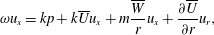 $$\begin{eqnarray}\displaystyle & \displaystyle \unicode[STIX]{x1D714}u_{x}=kp+k\overline{U}u_{x}+m\frac{\overline{W}}{r}u_{x}+\frac{\unicode[STIX]{x2202}\overline{U}}{\unicode[STIX]{x2202}r}u_{r}, & \displaystyle\end{eqnarray}$$
 $$\begin{eqnarray}\displaystyle & \displaystyle \unicode[STIX]{x1D714}u_{r}=-\frac{\unicode[STIX]{x2202}p}{\unicode[STIX]{x2202}r}+k\overline{U}u_{r}+m\frac{\overline{W}}{r}u_{r}+2\frac{\overline{W}}{r}u_{\unicode[STIX]{x1D703}}, & \displaystyle\end{eqnarray}$$
 $$\begin{eqnarray}\displaystyle & \displaystyle \unicode[STIX]{x1D714}u_{\unicode[STIX]{x1D703}}=\frac{m}{r}p+\left(\frac{\unicode[STIX]{x2202}\overline{W}}{\unicode[STIX]{x2202}r}+\frac{\overline{W}}{r}\right)u_{r}+k\overline{U}u_{\unicode[STIX]{x1D703}}+m\frac{\overline{W}}{r}u_{\unicode[STIX]{x1D703}}. & \displaystyle\end{eqnarray}$$
The stability analysis code is based on the Chebyshev spectral collocation method. The discretisation in the radial direction is performed on a Gauss–Lobatto–Chebyshev grid. It is mapped on a radially unbounded physical space
 $r/D=\unicode[STIX]{x1D701}/(1-\unicode[STIX]{x1D701}^{2}+(1/R_{max}))$
, where
$r/D=\unicode[STIX]{x1D701}/(1-\unicode[STIX]{x1D701}^{2}+(1/R_{max}))$
, where
 $\unicode[STIX]{x1D701}$
is the Chebyshev grid from 0 to 1 and
$\unicode[STIX]{x1D701}$
is the Chebyshev grid from 0 to 1 and
 $R_{max}=25$
is an arbitrarily large number to represent an unbounded space. The number of collocation points used is
$R_{max}=25$
is an arbitrarily large number to represent an unbounded space. The number of collocation points used is
 $N=120$
. The change in the results on doubling
$N=120$
. The change in the results on doubling
 $R_{max}$
and
$R_{max}$
and
 $N$
(not shown here) is less than a per cent.
$N$
(not shown here) is less than a per cent.
3.3 Stability analysis results
We first heuristically define the concepts of convective and absolute instabilities and their relation to the global flow instability (for detailed reviews please see Huerre & Monkewitz (Reference Huerre and Monkewitz1990) and Chomaz (Reference Chomaz2005)). A parallel flow is linearly stable if
 $\unicode[STIX]{x1D714}_{i}<0$
for all values of
$\unicode[STIX]{x1D714}_{i}<0$
for all values of
 $k$
, otherwise it is linearly unstable. In a linearly stable parallel flow, all external perturbations eventually die everywhere in the domain, whereas in a linearly unstable parallel flow, there are two possibilities. The first is the convective instability where perturbations of certain wavenumbers can grow but the growth rate is slower than the advection rate, i.e. perturbations get advected away from their origin. Mathematically, this happens when
$k$
, otherwise it is linearly unstable. In a linearly stable parallel flow, all external perturbations eventually die everywhere in the domain, whereas in a linearly unstable parallel flow, there are two possibilities. The first is the convective instability where perturbations of certain wavenumbers can grow but the growth rate is slower than the advection rate, i.e. perturbations get advected away from their origin. Mathematically, this happens when
 $\unicode[STIX]{x1D714}_{i}>0$
for some values of
$\unicode[STIX]{x1D714}_{i}>0$
for some values of
 $k$
, but the modes with zero group velocity (i.e.
$k$
, but the modes with zero group velocity (i.e.
 $\unicode[STIX]{x2202}\unicode[STIX]{x1D714}/\unicode[STIX]{x2202}k=0$
) have
$\unicode[STIX]{x2202}\unicode[STIX]{x1D714}/\unicode[STIX]{x2202}k=0$
) have
 $\unicode[STIX]{x1D714}_{i}<0$
. Such flows do not exhibit self-sustained oscillations but can greatly amplify external perturbations and are called amplifier flows. The second is the absolute instability where perturbations of certain wavenumbers can grow and the growth rate is faster than the advection rate (Tobias, Proctor & Knobloch Reference Tobias, Proctor and Knobloch1998) (i.e. at least one mode with
$\unicode[STIX]{x1D714}_{i}<0$
. Such flows do not exhibit self-sustained oscillations but can greatly amplify external perturbations and are called amplifier flows. The second is the absolute instability where perturbations of certain wavenumbers can grow and the growth rate is faster than the advection rate (Tobias, Proctor & Knobloch Reference Tobias, Proctor and Knobloch1998) (i.e. at least one mode with
 $\unicode[STIX]{x2202}\unicode[STIX]{x1D714}/\unicode[STIX]{x2202}k=0$
has
$\unicode[STIX]{x2202}\unicode[STIX]{x1D714}/\unicode[STIX]{x2202}k=0$
has
 $\unicode[STIX]{x1D714}_{i}>0$
). Such flows exhibit self-sustained oscillations and are called oscillator flows.
$\unicode[STIX]{x1D714}_{i}>0$
). Such flows exhibit self-sustained oscillations and are called oscillator flows.
These concepts of local stability analysis are applicable in weakly non-parallel flows where the basic flow varies on a longer length scale as compared to the instability wavelength (Monkewitz, Huerre & Chomaz Reference Monkewitz, Huerre and Chomaz1993; Chomaz Reference Chomaz2005). A weakly non-parallel flow is (i) stable – when it is locally linearly stable everywhere, (ii) an amplifier of external perturbations – when it is locally convectively unstable in some part of the domain, and (iii) an oscillator – when it is locally absolutely unstable in a sufficiently large region of the domain. A transition from stable to oscillator flow with increasing instability is shown in § 4.2.
Turbine wake flows are only locally convectively unstable (Iungo et al.
Reference Iungo, Viola, Camarri, Porté-Agel and Gallaire2013; Mao & Sørensen Reference Mao and Sørensen2018) and thus belong to the second class (i.e. amplifier flow). In figure 6(b–d), therefore, we present the stability results corresponding to the locally most amplified modes (unless explicitly stated, the results are for
 $\unicode[STIX]{x1D6FA}=10.5~\text{r.p.m.}$
case and
$\unicode[STIX]{x1D6FA}=10.5~\text{r.p.m.}$
case and
 $m=-1$
mode). Panel (b) shows the variation of the most amplified frequency (
$m=-1$
mode). Panel (b) shows the variation of the most amplified frequency (
 $\unicode[STIX]{x1D714}_{r}/2\unicode[STIX]{x03C0}$
) with
$\unicode[STIX]{x1D714}_{r}/2\unicode[STIX]{x03C0}$
) with
 $x/D$
. The near-wake region of the flow amplifies higher frequencies (compared to the far-wake region) because the mean flow in this region has smaller-scale features (such as the middle wake) and sharper shear layers. The sudden changes in the frequency signify mode switchings (determined by the mean flow feature that is dominant locally). Again, we do not scrutinise the origin of different near-wake modes. In the transition region, there is a clear shift from the higher to lower frequencies. Finally, in the far-wake region, there is a slow but consistent decrease in the most amplified frequency. Panels (c) and (d) show the corresponding spatial growth rate (
$x/D$
. The near-wake region of the flow amplifies higher frequencies (compared to the far-wake region) because the mean flow in this region has smaller-scale features (such as the middle wake) and sharper shear layers. The sudden changes in the frequency signify mode switchings (determined by the mean flow feature that is dominant locally). Again, we do not scrutinise the origin of different near-wake modes. In the transition region, there is a clear shift from the higher to lower frequencies. Finally, in the far-wake region, there is a slow but consistent decrease in the most amplified frequency. Panels (c) and (d) show the corresponding spatial growth rate (
 $k_{i}$
), the group velocity (
$k_{i}$
), the group velocity (
 $\unicode[STIX]{x2202}\unicode[STIX]{x1D714}/\unicode[STIX]{x2202}k|_{r}$
), and the diffusion term (
$\unicode[STIX]{x2202}\unicode[STIX]{x1D714}/\unicode[STIX]{x2202}k|_{r}$
), and the diffusion term (
 $-10(\unicode[STIX]{x2202}^{2}\unicode[STIX]{x1D714}/\unicode[STIX]{x2202}k^{2})|_{i}$
). The spatial growth rate has the same behaviour as
$-10(\unicode[STIX]{x2202}^{2}\unicode[STIX]{x1D714}/\unicode[STIX]{x2202}k^{2})|_{i}$
). The spatial growth rate has the same behaviour as
 $\unicode[STIX]{x1D714}_{sr}$
, it decreases slowly in the far-wake region as the flow evolves and the shear layers become less sharp. The group velocity signifies the advection rate of the perturbations and is roughly equal to 0.75 times the mean incoming velocity. The negative value of the diffusion term signifies that very high-frequency perturbations decay in the flow. The imaginary part of the group velocity (
$\unicode[STIX]{x1D714}_{sr}$
, it decreases slowly in the far-wake region as the flow evolves and the shear layers become less sharp. The group velocity signifies the advection rate of the perturbations and is roughly equal to 0.75 times the mean incoming velocity. The negative value of the diffusion term signifies that very high-frequency perturbations decay in the flow. The imaginary part of the group velocity (
 $\unicode[STIX]{x2202}\unicode[STIX]{x1D714}/\unicode[STIX]{x2202}k|_{i}$
) at (
$\unicode[STIX]{x2202}\unicode[STIX]{x1D714}/\unicode[STIX]{x2202}k|_{i}$
) at (
 $\unicode[STIX]{x1D714}_{s},k_{s}$
) is zero by definition, the linear dispersion term (
$\unicode[STIX]{x1D714}_{s},k_{s}$
) is zero by definition, the linear dispersion term (
 $\unicode[STIX]{x2202}^{2}\unicode[STIX]{x1D714}/\unicode[STIX]{x2202}k^{2}|_{r}$
) is negligibly small and the real wavenumber is given as
$\unicode[STIX]{x2202}^{2}\unicode[STIX]{x1D714}/\unicode[STIX]{x2202}k^{2}|_{r}$
) is negligibly small and the real wavenumber is given as
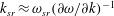 $k_{sr}\approx \unicode[STIX]{x1D714}_{sr}(\unicode[STIX]{x2202}\unicode[STIX]{x1D714}/\unicode[STIX]{x2202}k)^{-1}$
(please see appendix A).
$k_{sr}\approx \unicode[STIX]{x1D714}_{sr}(\unicode[STIX]{x2202}\unicode[STIX]{x1D714}/\unicode[STIX]{x2202}k)^{-1}$
(please see appendix A).
Additionally, in panel (a), we show the normalised eigenfunction components at locations
 $x/D=6$
, 7, 8 and 9 for the
$x/D=6$
, 7, 8 and 9 for the
 $m=0$
and
$m=0$
and
 $-1$
modes in terms of
$-1$
modes in terms of
 $\sqrt{u_{x}^{2}+u_{r}^{2}+u_{\unicode[STIX]{x1D703}}^{2}}$
from
$\sqrt{u_{x}^{2}+u_{r}^{2}+u_{\unicode[STIX]{x1D703}}^{2}}$
from
 $r/D=0$
to 1.2. Both the modes initially show two peaks (at
$r/D=0$
to 1.2. Both the modes initially show two peaks (at
 $r/D\approx 0.2$
and 0.5), but later at
$r/D\approx 0.2$
and 0.5), but later at
 $x/D=9.0$
, only the outer peak at
$x/D=9.0$
, only the outer peak at
 $r/D\approx 0.5$
survives. The eigenfunctions show the flow region in the radial direction where the wake meandering is influential (see (4.5)). In panel (b), we show the variation of the most amplified frequency in the
$r/D\approx 0.5$
survives. The eigenfunctions show the flow region in the radial direction where the wake meandering is influential (see (4.5)). In panel (b), we show the variation of the most amplified frequency in the
 $\unicode[STIX]{x1D6FA}=12.0~\text{r.p.m.}$
and 9.0 r.p.m. cases (only after their respective transition regions). The results for these flow cases are qualitatively similar, implications of this similarity are explored in § 5.1. In panel (c), we show the spatial growth rates for the
$\unicode[STIX]{x1D6FA}=12.0~\text{r.p.m.}$
and 9.0 r.p.m. cases (only after their respective transition regions). The results for these flow cases are qualitatively similar, implications of this similarity are explored in § 5.1. In panel (c), we show the spatial growth rates for the
 $m=1$
, 0 and
$m=1$
, 0 and
 $-2$
modes, which indicate that the local stability results are very similar for all the azimuthal modes (see § 4.2).
$-2$
modes, which indicate that the local stability results are very similar for all the azimuthal modes (see § 4.2).
4 Low-order modelling of the far-wake region
For spatially developing open shear flows, such as jets and wakes, Chomaz and co-workers (Chomaz et al. Reference Chomaz, Huerre and Redekopp1988; Chomaz, Huerre & Redekopp Reference Chomaz, Huerre, Redekopp, Coullet and Huerre1990, Reference Chomaz, Huerre and Redekopp1991; Chomaz Reference Chomaz1992; Le Dizès et al. Reference Le Dizès, Huerre, Chomaz and Monkewitz1996; Cossu & Chomaz Reference Cossu and Chomaz1997) pioneered the use of the complex Ginzburg–Landau (CGL) equation given as
 $$\begin{eqnarray}{\dot{A}}=(\unicode[STIX]{x1D70E}_{r}+\text{i}\unicode[STIX]{x1D70E}_{i})A-U_{g}\unicode[STIX]{x2202}_{x}A+(c_{dr}+\text{i}c_{di})\unicode[STIX]{x2202}_{x}^{2}A-(c_{nr}+\text{i}c_{ni})|A|^{2}A.\end{eqnarray}$$
This equation governs the evolution of a hydrodynamic instability wave (in terms of the complex amplitude
 $A=|A|\text{e}^{\text{i}\unicode[STIX]{x1D719}}$
, where
$A=|A|\text{e}^{\text{i}\unicode[STIX]{x1D719}}$
, where
 $\unicode[STIX]{x1D719}$
is its phase) travelling downstream at the group velocity
$\unicode[STIX]{x1D719}$
is its phase) travelling downstream at the group velocity
 $U_{g}$
. The growth rate
$U_{g}$
. The growth rate
 $\unicode[STIX]{x1D70E}_{r}$
is the driving term,
$\unicode[STIX]{x1D70E}_{r}$
is the driving term,
 $\unicode[STIX]{x1D70E}_{i}$
is the frequency shift,
$\unicode[STIX]{x1D70E}_{i}$
is the frequency shift,
 $c_{dr}$
(
$c_{dr}$
(
 ${>}0$
) is the diffusive coupling coefficient,
${>}0$
) is the diffusive coupling coefficient,
 $c_{nr}$
(
$c_{nr}$
(
 ${>}0$
) is the nonlinear saturation coefficient and
${>}0$
) is the nonlinear saturation coefficient and
 $c_{di}$
and
$c_{di}$
and
 $c_{ni}$
are the linear and nonlinear dispersion coefficients, respectively.
$c_{ni}$
are the linear and nonlinear dispersion coefficients, respectively.
4.1 Model deduction
Strictly, the CGL equation is limited to describing instability waves in flows that are (i) weakly nonlinear and (ii) weakly non-parallel (Aranson & Kramer Reference Aranson and Kramer2002; van Saarloos Reference van Saarloos2003). The first condition is satisfied when a flow is only marginally unstable (i.e. has just transited to the oscillator regime) and ensures the absence of the higher harmonics. The second condition ensures that instability waves satisfy the local dispersion relations as per the WKBJ approximation (Monkewitz et al. Reference Monkewitz, Huerre and Chomaz1993). Thus, it provides a way to obtain the linearised CGL coefficients from the local stability results (Le Dizès et al. Reference Le Dizès, Huerre, Chomaz and Monkewitz1996) as
 $$\begin{eqnarray}\displaystyle \dot{\tilde{A}} & = & \displaystyle -1\text{i}\left(\unicode[STIX]{x1D714}_{0}(X)+\frac{1}{2}\frac{\unicode[STIX]{x2202}^{2}\unicode[STIX]{x1D714}}{\unicode[STIX]{x2202}k^{2}}(\unicode[STIX]{x1D714}_{0},k_{0};X)k_{0}(X)^{2}\right)\tilde{A}+\frac{\unicode[STIX]{x2202}^{2}\unicode[STIX]{x1D714}}{\unicode[STIX]{x2202}k^{2}}(\unicode[STIX]{x1D714}_{0},k_{0};X)k_{0}(X)\unicode[STIX]{x2202}_{x}\tilde{A}\nonumber\\ \displaystyle & & \displaystyle +\,\frac{1\text{i}}{2}\frac{\unicode[STIX]{x2202}^{2}\unicode[STIX]{x1D714}}{\unicode[STIX]{x2202}k^{2}}(\unicode[STIX]{x1D714}_{0},k_{0};X)\unicode[STIX]{x2202}_{x}^{2}\tilde{A},\end{eqnarray}$$
where
 $X\equiv \unicode[STIX]{x1D716}x$
(
$X\equiv \unicode[STIX]{x1D716}x$
(
 $\unicode[STIX]{x1D716}\ll 1$
) is the slow scale at which the basic flow varies,
$\unicode[STIX]{x1D716}\ll 1$
) is the slow scale at which the basic flow varies,
 $\unicode[STIX]{x1D714}_{0}(X)$
and
$\unicode[STIX]{x1D714}_{0}(X)$
and
 $k_{0}(X)$
are the complex frequency and wavenumber, respectively, at
$k_{0}(X)$
are the complex frequency and wavenumber, respectively, at
 $X$
corresponding to the zero group velocity modes (i.e.
$X$
corresponding to the zero group velocity modes (i.e.
 $\unicode[STIX]{x2202}\unicode[STIX]{x1D714}/\unicode[STIX]{x2202}k(\unicode[STIX]{x1D714}_{0},k_{0};X)=0$
) and
$\unicode[STIX]{x2202}\unicode[STIX]{x1D714}/\unicode[STIX]{x2202}k(\unicode[STIX]{x1D714}_{0},k_{0};X)=0$
) and
 $\tilde{A}$
is the linear counterpart of
$\tilde{A}$
is the linear counterpart of
 $A$
. Following Crighton & Gaster (Reference Crighton and Gaster1976), Monkewitz et al. (Reference Monkewitz, Huerre and Chomaz1993) and Siconolfi et al. (Reference Siconolfi, Citro, Giannetti, Camarri and Luchini2017), linear self-sustained oscillations in a weakly non-parallel flow can be approximated as
$A$
. Following Crighton & Gaster (Reference Crighton and Gaster1976), Monkewitz et al. (Reference Monkewitz, Huerre and Chomaz1993) and Siconolfi et al. (Reference Siconolfi, Citro, Giannetti, Camarri and Luchini2017), linear self-sustained oscillations in a weakly non-parallel flow can be approximated as
 $$\begin{eqnarray}\tilde{A}(x,r,\unicode[STIX]{x1D703},t)=W_{g}(X)q_{g}(r,\unicode[STIX]{x1D703};X)\exp \left[\text{i}\unicode[STIX]{x1D716}^{-1}\int ^{X}k_{g}(X^{\prime })\,\text{d}X^{\prime }-\text{i}\unicode[STIX]{x1D714}_{g}t\right],\end{eqnarray}$$
where
 $W_{g}(X)$
is the slow amplitude variation,
$W_{g}(X)$
is the slow amplitude variation,
 $q_{g}(r,\unicode[STIX]{x1D703};X)$
and
$q_{g}(r,\unicode[STIX]{x1D703};X)$
and
 $k_{g}(X)$
are the local eigenfunction and wavenumber, respectively, corresponding to the complex global mode frequency
$k_{g}(X)$
are the local eigenfunction and wavenumber, respectively, corresponding to the complex global mode frequency
 $\unicode[STIX]{x1D714}_{g}$
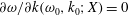
. In order to check the applicability of (4.2), we insert (4.3) in (4.2) and retain only the leading-order terms (at
$\unicode[STIX]{x1D714}_{g}$
. In order to check the applicability of (4.2), we insert (4.3) in (4.2) and retain only the leading-order terms (at
 $O(\unicode[STIX]{x1D716}^{0})$
). The resultant equation is the local linear dispersion relation at
$O(\unicode[STIX]{x1D716}^{0})$
). The resultant equation is the local linear dispersion relation at
 $X$
up to the second-order term as
$X$
up to the second-order term as
 $$\begin{eqnarray}\unicode[STIX]{x1D714}_{g}-\unicode[STIX]{x1D714}_{0}(X)=\frac{1}{2}\frac{\unicode[STIX]{x2202}^{2}\unicode[STIX]{x1D714}}{\unicode[STIX]{x2202}k^{2}}(\unicode[STIX]{x1D714}_{0},k_{0};X)(k_{g}(X)-k_{0}(X))^{2}.\end{eqnarray}$$
Although, in general, flows have higher-order terms in their dispersion relations, they can be neglected because in a weakly non-parallel flow
 $\unicode[STIX]{x1D714}_{g}$
is close to
$\unicode[STIX]{x1D714}_{g}$
is close to
 $\unicode[STIX]{x1D714}_{0}(X)$
(Chomaz et al.
Reference Chomaz, Huerre and Redekopp1991; Monkewitz et al.
Reference Monkewitz, Huerre and Chomaz1993; Le Dizès et al.
Reference Le Dizès, Huerre, Chomaz and Monkewitz1996; Pier & Huerre Reference Pier and Huerre2001; Pier Reference Pier2002).
$\unicode[STIX]{x1D714}_{0}(X)$
(Chomaz et al.
Reference Chomaz, Huerre and Redekopp1991; Monkewitz et al.
Reference Monkewitz, Huerre and Chomaz1993; Le Dizès et al.
Reference Le Dizès, Huerre, Chomaz and Monkewitz1996; Pier & Huerre Reference Pier and Huerre2001; Pier Reference Pier2002).
In contrast to self-sustained oscillations modelled by (4.2), wake meandering arises from amplification of upstream disturbances (see §§ 1 and 2). We argue that (i) the CGL equation can still be used to model wake meandering and (ii) its coefficients can still be obtained from local stability results. In support of the first argument, Cossu & Chomaz (Reference Cossu and Chomaz1997), Tobias et al. (Reference Tobias, Proctor and Knobloch1998) and Bagheri et al. (Reference Bagheri, Henningson, Hœpffner and Schmid2009) showed that flow structures arising from the amplification of upstream perturbations can be qualitatively modelled using the CGL equation. In support of the second argument, Gaster (Reference Gaster1969) showed that spatially amplified modes can be modelled using a wave equation tuned by local mean flow parameters. More formally, Chomaz (Reference Chomaz2005) and Viola, Arratia & Gallaire (Reference Viola, Arratia and Gallaire2016) showed that similar to (4.3), the linear response to sinusoidal forcing (say at frequency
 $\unicode[STIX]{x1D714}_{f}$
) in weakly non-parallel flows can be approximated as
$\unicode[STIX]{x1D714}_{f}$
) in weakly non-parallel flows can be approximated as
 $$\begin{eqnarray}\tilde{A}(x,r,\unicode[STIX]{x1D703},t)=W_{f}(X)q_{f}(r,\unicode[STIX]{x1D703};X)\exp \left[\text{i}\unicode[STIX]{x1D716}^{-1}\int ^{X}k_{f}(X^{\prime })\,\text{d}X^{\prime }-\text{i}\unicode[STIX]{x1D714}_{f}t\right],\end{eqnarray}$$
where
 $W_{f}$
is the slow amplitude variation,
$W_{f}$
is the slow amplitude variation,
 $q_{f}(r,\unicode[STIX]{x1D703};X)$
and
$q_{f}(r,\unicode[STIX]{x1D703};X)$
and
 $k_{f}(X)$
are the local eigenfunction and wavenumber, respectively, corresponding to
$k_{f}(X)$
are the local eigenfunction and wavenumber, respectively, corresponding to
 $\unicode[STIX]{x1D714}_{f}$
. The range of
$\unicode[STIX]{x1D714}_{f}$
. The range of
 $\unicode[STIX]{x1D714}_{f}$
that is of interest is where the spatial amplification is maximum, which is at
$\unicode[STIX]{x1D714}_{f}$
that is of interest is where the spatial amplification is maximum, which is at
 $\unicode[STIX]{x1D714}_{s}(X)$
(see § 3.3). The CGL equation to describe the spatially amplified waves, therefore, should be based on the dispersion relation around
$\unicode[STIX]{x1D714}_{s}(X)$
(see § 3.3). The CGL equation to describe the spatially amplified waves, therefore, should be based on the dispersion relation around
 $(\unicode[STIX]{x1D714}_{s},k_{s})$
(see appendix A) and can be written as
$(\unicode[STIX]{x1D714}_{s},k_{s})$
(see appendix A) and can be written as
 $$\begin{eqnarray}\displaystyle {\dot{A}} & = & \displaystyle -1\text{i}\left(\unicode[STIX]{x1D714}_{s}(X)-\frac{\unicode[STIX]{x2202}\unicode[STIX]{x1D714}}{\unicode[STIX]{x2202}k}(\unicode[STIX]{x1D714}_{s},k_{s};X)k_{s}(X)+\frac{1}{2}\frac{\unicode[STIX]{x2202}^{2}\unicode[STIX]{x1D714}}{\unicode[STIX]{x2202}k^{2}}(\unicode[STIX]{x1D714}_{s},k_{s};X)k_{s}(X)^{2}\right)A\nonumber\\ \displaystyle & & \displaystyle -\left(\frac{\unicode[STIX]{x2202}\unicode[STIX]{x1D714}}{\unicode[STIX]{x2202}k}(\unicode[STIX]{x1D714}_{s},k_{s};X)-\frac{\unicode[STIX]{x2202}^{2}\unicode[STIX]{x1D714}}{\unicode[STIX]{x2202}k^{2}}(\unicode[STIX]{x1D714}_{s},k_{s};X)k_{s}(X)\right)\unicode[STIX]{x2202}_{x}A+\frac{1\text{i}}{2}\frac{\unicode[STIX]{x2202}^{2}\unicode[STIX]{x1D714}}{\unicode[STIX]{x2202}k^{2}}(x)\unicode[STIX]{x2202}_{x}^{2}A-C_{n}(X)|A|^{2}A.\nonumber\\ \displaystyle & & \displaystyle\end{eqnarray}$$
It should be noted here that we replaced
 $\tilde{A}$
by its nonlinear counterpart
$\tilde{A}$
by its nonlinear counterpart
 $A$
and also included the nonlinear term (
$A$
and also included the nonlinear term (
 $C_{n}\equiv c_{nr}+\text{i}c_{ni}$
). The conversion from the linear to nonlinear CGL equation in not trivial and is discussed in detail in § 5.2.
$C_{n}\equiv c_{nr}+\text{i}c_{ni}$
). The conversion from the linear to nonlinear CGL equation in not trivial and is discussed in detail in § 5.2.
Equation (4.6) is solved in the range
 $X=0{-}12$
, where
$X=0{-}12$
, where
 $X$
is equivalent to
$X$
is equivalent to
 $x/D$
in the wake flow. At the inlet (
$x/D$
in the wake flow. At the inlet (
 $X=0$
), the boundary condition is set as time-dependent forcing, which can be an impulse, sinusoidal or white noise forcing or their combination. At the outlet (
$X=0$
), the boundary condition is set as time-dependent forcing, which can be an impulse, sinusoidal or white noise forcing or their combination. At the outlet (
 $X=12$
), following Heaton, Nichols & Schmid (Reference Heaton, Nichols and Schmid2009), the boundary condition is set as a convective outflow. We convert the partial differential equation to a set of ordinary differential equations by discretising the spatial coordinate using the fourth-order accurate central differencing scheme (
$X=12$
), following Heaton, Nichols & Schmid (Reference Heaton, Nichols and Schmid2009), the boundary condition is set as a convective outflow. We convert the partial differential equation to a set of ordinary differential equations by discretising the spatial coordinate using the fourth-order accurate central differencing scheme (
 $\text{d}X=1/32$
). We then use the implicit Crank–Nicolson scheme (
$\text{d}X=1/32$
). We then use the implicit Crank–Nicolson scheme (
 $\text{d}t=0.04$
) for time marching and Picard’s method for iterating the nonlinear term.
$\text{d}t=0.04$
) for time marching and Picard’s method for iterating the nonlinear term.
4.2 Model coefficients

Figure 7. The coefficients are determined using least-square polynomial curve fits (red lines) to the local stability results at
 $m=-1$
(black lines) in the region
$m=-1$
(black lines) in the region
 $X=4.5{-}10.0$
.
$X=4.5{-}10.0$
.
Figure 7 shows the model coefficients (
 $\unicode[STIX]{x1D714}_{sr}/2\unicode[STIX]{x03C0}$
,
$\unicode[STIX]{x1D714}_{sr}/2\unicode[STIX]{x03C0}$
,
 $k_{si}$
,
$k_{si}$
,
 $\unicode[STIX]{x2202}\unicode[STIX]{x1D714}/\unicode[STIX]{x2202}k(\unicode[STIX]{x1D714}_{s},k_{s})|_{r}$
and
$\unicode[STIX]{x2202}\unicode[STIX]{x1D714}/\unicode[STIX]{x2202}k(\unicode[STIX]{x1D714}_{s},k_{s})|_{r}$
and
 $\unicode[STIX]{x2202}^{2}\unicode[STIX]{x1D714}/\unicode[STIX]{x2202}k^{2}$
 $(\unicode[STIX]{x1D714}_{s},k_{s})|_{i}$
), which are determined directly by least-square polynomial curve fitting of the local stability results at
$(\unicode[STIX]{x1D714}_{s},k_{s})|_{i}$
), which are determined directly by least-square polynomial curve fitting of the local stability results at
 $m=-1$
in the region
$m=-1$
in the region
 $X=4.5{-}10.0$
(presented in figure 6). In the near-wake region (
$X=4.5{-}10.0$
(presented in figure 6). In the near-wake region (
 $X<4.5$
), the coefficients are extrapolated (as shown in the figure) such that the model response and turbine wake flow results roughly match in the region
$X<4.5$
), the coefficients are extrapolated (as shown in the figure) such that the model response and turbine wake flow results roughly match in the region
 $X=2.0{-}3.0$
(see § 5.1). In principle, the model coefficients should be fixed separately for different azimuthal modes and thus different CGL equations should be used for the forced response based on the azimuthal wavenumber of the inflow disturbances. However, the stability results are very similar at all
$X=2.0{-}3.0$
(see § 5.1). In principle, the model coefficients should be fixed separately for different azimuthal modes and thus different CGL equations should be used for the forced response based on the azimuthal wavenumber of the inflow disturbances. However, the stability results are very similar at all
 $m$
(as shown in figure 6
c). We, therefore, assume that a single CGL equation should be able to qualitatively model the evolution of all
$m$
(as shown in figure 6
c). We, therefore, assume that a single CGL equation should be able to qualitatively model the evolution of all
 $m$
modes.
$m$
modes.

Figure 8. The linear impulse response of the system (a) decays monotonically (stable regime), (b) shows transient growth (amplifier regime – present case), (c) exhibits nearly self-sustained oscillations (marginally close to the oscillator regime) and (d) exhibits exponentially growing oscillations (oscillator regime). The lines correspond to the response amplitude at
 $X=\{1,2,3,\ldots ,10\}$
(the arrows indicate increasing
$X=\{1,2,3,\ldots ,10\}$
(the arrows indicate increasing
 $X$
).
$X$
).
Figure 8 shows the linear impulse response of the model (panel b) as well as for its variants (panels a, cand d). An impulse of magnitude 1 is applied at
 $X=0$
at time
$X=0$
at time
 $t=0$
, and the response amplitudes at
$t=0$
, and the response amplitudes at
 $X=\{1,2,3,\ldots ,10\}$
with time are plotted. Panels (a–d) show transition from (a) the stable regime to (b) the amplifier regime to (c) being marginally close to the oscillator regime and finally to (d) the oscillator regime as the flow instability increases. In the stable regime in (a), a disturbance dies down monotonically. In the amplifier regime in (b), a disturbance shows a transient growth via a convective-type non-normality (Cossu & Chomaz Reference Cossu and Chomaz1997) before eventually decaying. The flow is still in the amplifier regime but is marginally close to the oscillator regime in (c). The transient growth in this case is much higher and the decay rate is much slower as compared to those in (b). Thus, even small external noise can sustain oscillations in such a flow (Huerre & Monkewitz Reference Huerre and Monkewitz1990; Babcock, Ahlers & Cannell Reference Babcock, Ahlers and Cannell1991). In the oscillator regime in (d), a disturbance grows exponentially until the nonlinearities saturate the oscillations to a finite amplitude. This figure confirms that, like the wake flow, the model (i) is in the amplifier regime and (ii) can spatially amplify the incoming disturbances.
$X=\{1,2,3,\ldots ,10\}$
with time are plotted. Panels (a–d) show transition from (a) the stable regime to (b) the amplifier regime to (c) being marginally close to the oscillator regime and finally to (d) the oscillator regime as the flow instability increases. In the stable regime in (a), a disturbance dies down monotonically. In the amplifier regime in (b), a disturbance shows a transient growth via a convective-type non-normality (Cossu & Chomaz Reference Cossu and Chomaz1997) before eventually decaying. The flow is still in the amplifier regime but is marginally close to the oscillator regime in (c). The transient growth in this case is much higher and the decay rate is much slower as compared to those in (b). Thus, even small external noise can sustain oscillations in such a flow (Huerre & Monkewitz Reference Huerre and Monkewitz1990; Babcock, Ahlers & Cannell Reference Babcock, Ahlers and Cannell1991). In the oscillator regime in (d), a disturbance grows exponentially until the nonlinearities saturate the oscillations to a finite amplitude. This figure confirms that, like the wake flow, the model (i) is in the amplifier regime and (ii) can spatially amplify the incoming disturbances.
The nonlinear saturation term (
 $c_{nr}$
) represents the reduction in amplification of disturbances with their amplitude. It is observed in § 2.3, that this reduction is higher at the higher forcing frequencies (
$c_{nr}$
) represents the reduction in amplification of disturbances with their amplitude. It is observed in § 2.3, that this reduction is higher at the higher forcing frequencies (
 $St_{f}$
). Thus,
$St_{f}$
). Thus,
 $c_{nr}$
should be proportional to a positive exponent of
$c_{nr}$
should be proportional to a positive exponent of
 $St_{f}$
. Among the exponents tried (0.5, 1.0, 1.5 and 2.0), 1.5 gives the best results. Thus leading to
$St_{f}$
. Among the exponents tried (0.5, 1.0, 1.5 and 2.0), 1.5 gives the best results. Thus leading to
 $c_{nr}=4(2\unicode[STIX]{x03C0}St_{f})^{1.5}$
, where the pre-multiplication factor controls the level of the saturation. The nonlinear dispersion term (
$c_{nr}=4(2\unicode[STIX]{x03C0}St_{f})^{1.5}$
, where the pre-multiplication factor controls the level of the saturation. The nonlinear dispersion term (
 $c_{ni}$
) represents the change in the wavenumber with the forcing amplitude and, similar to the linear dispersion term, is set as zero. When a number of frequencies are present in the boundary forcing, the nonlinear saturation term is set as
$c_{ni}$
) represents the change in the wavenumber with the forcing amplitude and, similar to the linear dispersion term, is set as zero. When a number of frequencies are present in the boundary forcing, the nonlinear saturation term is set as
 $c_{nr}(X)=4(2\unicode[STIX]{x03C0}(\unicode[STIX]{x1D6F4}_{j}A_{fj}St_{fj}G_{Lj}(X)/\unicode[STIX]{x1D6F4}_{j}A_{fj}G_{Lj}(X)))^{1.5}$
, where
$c_{nr}(X)=4(2\unicode[STIX]{x03C0}(\unicode[STIX]{x1D6F4}_{j}A_{fj}St_{fj}G_{Lj}(X)/\unicode[STIX]{x1D6F4}_{j}A_{fj}G_{Lj}(X)))^{1.5}$
, where
 $A_{fj}$
and
$A_{fj}$
and
 $G_{Lj}(X)$
are the forcing amplitude and the linear gain corresponding to the forcing frequency
$G_{Lj}(X)$
are the forcing amplitude and the linear gain corresponding to the forcing frequency
 $St_{fj}$
(linear gains at some frequencies are shown in appendix B). The implications of the nonlinear coefficient and alternative ways for its mathematically rigorous calculation are discussed in § 5.2.
$St_{fj}$
(linear gains at some frequencies are shown in appendix B). The implications of the nonlinear coefficient and alternative ways for its mathematically rigorous calculation are discussed in § 5.2.
4.3 Model behaviour

Figure 9. The model response to white Gaussian noise forcing (
 $A_{w}=0.0004$
) in terms of the PSDs (
$A_{w}=0.0004$
) in terms of the PSDs (
 $\unicode[STIX]{x1D719}_{A}$
) at
$\unicode[STIX]{x1D719}_{A}$
) at
 $X=\{1,2,3,\ldots ,10\}$
. The oscillations evolve towards lower frequencies with increasing
$X=\{1,2,3,\ldots ,10\}$
. The oscillations evolve towards lower frequencies with increasing
 $X$
(indicated by the arrow) and finally have a broad peak at
$X$
(indicated by the arrow) and finally have a broad peak at
 $St\approx 0.5$
.
$St\approx 0.5$
.
Turbines operate under conditions comprising of small-scale turbulence as well as coherent structures arising from a number of sources. Therefore, we study the model behaviour when inflow conditions (at
 $X=0$
) are set as combinations of white Gaussian noise (representing small-scale turbulence) and sinusoidal forcing (representing coherent structures). Although simplistic, such input–output analyses are shown to be useful in understanding the origin of complex structures arising in turbulent flows (see § 2.3).
$X=0$
) are set as combinations of white Gaussian noise (representing small-scale turbulence) and sinusoidal forcing (representing coherent structures). Although simplistic, such input–output analyses are shown to be useful in understanding the origin of complex structures arising in turbulent flows (see § 2.3).
Figure 9 shows the model response to white Gaussian noise forcing (of normalised amplitude
 $A_{w}=0.0004$
) in terms of the PSDs at
$A_{w}=0.0004$
) in terms of the PSDs at
 $X=\{1,2,3,\ldots ,10\}$
. The PSDs evolve towards lower frequencies and have a broad peak at
$X=\{1,2,3,\ldots ,10\}$
. The PSDs evolve towards lower frequencies and have a broad peak at
 $St\approx 0.5$
in the downstream region, which matches well with the wake flow PSDs shown in figure 1(d). The peak is broader here because the background noise is white, unlike in turbine far wake where it consists of the near-wake structures. In addition to the white noise, which is present in all the subsequent simulations, we add an upstream sinusoidal forcing term (of normalised amplitude
$St\approx 0.5$
in the downstream region, which matches well with the wake flow PSDs shown in figure 1(d). The peak is broader here because the background noise is white, unlike in turbine far wake where it consists of the near-wake structures. In addition to the white noise, which is present in all the subsequent simulations, we add an upstream sinusoidal forcing term (of normalised amplitude
 $A_{f}$
and frequency
$A_{f}$
and frequency
 $St_{f}$
) at
$St_{f}$
) at
 $X=0$
. Figure 10 shows the model responses to forcing at varying
$X=0$
. Figure 10 shows the model responses to forcing at varying
 $St_{f}$
and
$St_{f}$
and
 $A_{f}$
in terms of
$A_{f}$
in terms of
 $r_{fm}=\unicode[STIX]{x1D719}_{A}(St_{f})/\unicode[STIX]{x1D719}_{A}(St_{f})+\unicode[STIX]{x1D719}_{A}(St_{max})$
, where
$r_{fm}=\unicode[STIX]{x1D719}_{A}(St_{f})/\unicode[STIX]{x1D719}_{A}(St_{f})+\unicode[STIX]{x1D719}_{A}(St_{max})$
, where
 $\unicode[STIX]{x1D719}_{A}(St_{f})$
and
$\unicode[STIX]{x1D719}_{A}(St_{f})$
and
 $\unicode[STIX]{x1D719}_{A}(St_{max})$
are the PSD values (at
$\unicode[STIX]{x1D719}_{A}(St_{max})$
are the PSD values (at
 $X=9$
) at the forcing frequency (
$X=9$
) at the forcing frequency (
 $St_{f}$
) and at the frequency (
$St_{f}$
) and at the frequency (
 $St_{max}$
) where the response is maximum but
$St_{max}$
) where the response is maximum but
 $St_{max}\neq St_{f}$
. The ratio
$St_{max}\neq St_{f}$
. The ratio
 $r_{fm}$
is nearly zero when the background noise is dominant and approaches one as the sinusoidal forcing suppresses the effect of the background noise. The black line shows the pseudo lock-in curve (
$r_{fm}$
is nearly zero when the background noise is dominant and approaches one as the sinusoidal forcing suppresses the effect of the background noise. The black line shows the pseudo lock-in curve (
 $r_{fm}\approx 0.95$
), i.e. the minimum
$r_{fm}\approx 0.95$
), i.e. the minimum
 $A_{f}$
at a given
$A_{f}$
at a given
 $St_{f}$
where the effect of the background noise is suppressed. Similar to that for the wake flow in figure 4, pseudo lock-in is achieved at lower
$St_{f}$
where the effect of the background noise is suppressed. Similar to that for the wake flow in figure 4, pseudo lock-in is achieved at lower
 $A_{f}$
when
$A_{f}$
when
 $St_{f}\approx 0.54{-}0.65$
, which is close to
$St_{f}\approx 0.54{-}0.65$
, which is close to
 $St_{m}\approx 0.52$
, and the pseudo lock-in curve is parabola like in shape with a tilt towards
$St_{m}\approx 0.52$
, and the pseudo lock-in curve is parabola like in shape with a tilt towards
 $St_{f}>St_{m}$
.
$St_{f}>St_{m}$
.

Figure 10. The model response to sinusoidal forcing in terms of
 $r_{fm}$
, which is nearly zero when the background noise is dominant and approaches one as the sinusoidal forcing becomes dominant. The black line represents the pseudo lock-in curve (
$r_{fm}$
, which is nearly zero when the background noise is dominant and approaches one as the sinusoidal forcing becomes dominant. The black line represents the pseudo lock-in curve (
 $r_{fm}\approx 0.95$
), above which the sinusoidal forcing has suppressed the effect of the background noise. Pseudo lock-in is achieved at lower
$r_{fm}\approx 0.95$
), above which the sinusoidal forcing has suppressed the effect of the background noise. Pseudo lock-in is achieved at lower
 $A_{f}$
when
$A_{f}$
when
 $St_{f}$
is close to
$St_{f}$
is close to
 $St_{m}\;({\approx}0.52)$
.
$St_{m}\;({\approx}0.52)$
.
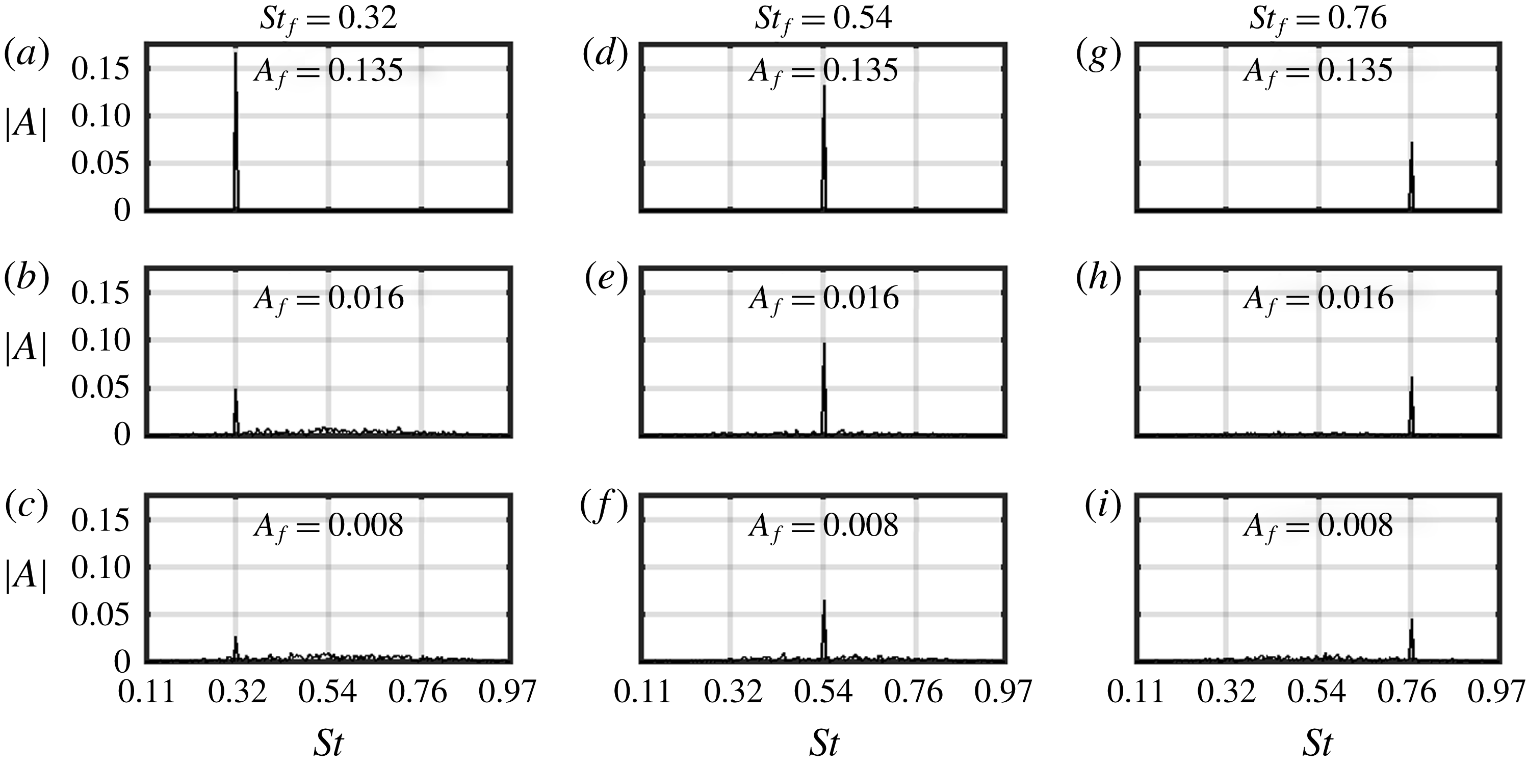
Figure 11. The model response to forcing at frequencies (a–c) 0.32, (d–f) 0.54 and (g–i) 0.76 and at varying
 $A_{f}$
(increasing from bottom to top) in terms of the spectra at
$A_{f}$
(increasing from bottom to top) in terms of the spectra at
 $X=9$
. As
$X=9$
. As
 $A_{f}$
increases, the maximum model response shifts from
$A_{f}$
increases, the maximum model response shifts from
 $St_{f}=0.54$
to
$St_{f}=0.54$
to
 $St_{f}=0.32$
. Thus showing a shift to lower frequencies with increasing forcing amplitude.
$St_{f}=0.32$
. Thus showing a shift to lower frequencies with increasing forcing amplitude.
Figure 11 presents the model responses (in terms of the frequency spectrum at
 $X=9$
) to sinusoidal forcing at varying
$X=9$
) to sinusoidal forcing at varying
 $St_{f}$
(increasing from the left to right) and
$St_{f}$
(increasing from the left to right) and
 $A_{f}$
(increasing from the bottom to top). The maximum response shifts from
$A_{f}$
(increasing from the bottom to top). The maximum response shifts from
 $St_{f}=0.54$
to 0.32 as the forcing amplitude increases. This shows a shift towards lower frequencies with increasing
$St_{f}=0.54$
to 0.32 as the forcing amplitude increases. This shows a shift towards lower frequencies with increasing
 $A_{f}$
, as also seen for the wake flow in figure 5 and Mao & Sørensen (Reference Mao and Sørensen2018).
$A_{f}$
, as also seen for the wake flow in figure 5 and Mao & Sørensen (Reference Mao and Sørensen2018).
5 Results and discussion
5.1 Achievements of the low-order model
The match between figures 10 and 11 with figures 4 and 5, respectively, shows how well the CGL equation models the convectively amplified flow structures that give rise to wake meandering. Thus, justifying the use of the CGL equation (4.6) for modelling wake meandering. Here, we present a more detailed comparison between the model and the wake flow results. It should be noted that we only qualitatively model the wake from
 $x/D=4.5$
to 9.5. The quantitative match between the two arises because the model is designed to roughly match the wake flow in the region
$x/D=4.5$
to 9.5. The quantitative match between the two arises because the model is designed to roughly match the wake flow in the region
 $x/D=2.0$
to 3.0. The model output
$x/D=2.0$
to 3.0. The model output
 $|A|$
is equivalent to the wake flow response amplitude calculated as the summation of
$|A|$
is equivalent to the wake flow response amplitude calculated as the summation of
 $E_{f}$
at
$E_{f}$
at
 $St_{f}$
and its harmonics (see figure 5) and then averaged over
$St_{f}$
and its harmonics (see figure 5) and then averaged over
 $z/D=0.0{-}0.5$
.
$z/D=0.0{-}0.5$
.
5.1.1 Variations in the wake meandering features with the forcing parameters

Figure 12. Comparison of the wake flow and the model responses to forcing at frequencies (a,b) 0.32, (c,d) 0.54 and (e,f) 0.76 and at two forcing amplitudes. The wake meandering frequency shifts to lower values with increasing (i)
 $x/D$
and (ii)
$x/D$
and (ii)
 $A_{f}$
.
$A_{f}$
.
Figure 12 shows the variations of the wake flow and the model response amplitudes with the streamwise distance from the turbine. The results are presented for three forcing frequencies (increasing from left to right) and two forcing amplitudes (a,c,e–
 $A_{f}=0.016$
, b,d,f–
$A_{f}=0.016$
, b,d,f–
 $A_{f}=0.135$
). There are two main points to note from this figure. The first is the change in the dominant frequency with the downstream distance. The top row shows that the response at
$A_{f}=0.135$
). There are two main points to note from this figure. The first is the change in the dominant frequency with the downstream distance. The top row shows that the response at
 $St_{f}=0.32$
increases in the streamwise direction up to
$St_{f}=0.32$
increases in the streamwise direction up to
 $x/D\approx 10$
, while the responses at
$x/D\approx 10$
, while the responses at
 $St_{f}=0.54$
and
$St_{f}=0.54$
and
 $St_{f}=0.76$
initially increase up to
$St_{f}=0.76$
initially increase up to
 $x/D\approx 9$
and
$x/D\approx 9$
and
 $x/D\approx 7$
, respectively, and then decrease. Consequently, up to
$x/D\approx 7$
, respectively, and then decrease. Consequently, up to
 $x/D\approx 6$
, the wake flow response at
$x/D\approx 6$
, the wake flow response at
 $St_{f}=0.76$
is dominant while after that the response at
$St_{f}=0.76$
is dominant while after that the response at
 $St_{f}=0.54$
is dominant. The bottom row shows qualitatively similar behaviour, where the wake flow response at
$St_{f}=0.54$
is dominant. The bottom row shows qualitatively similar behaviour, where the wake flow response at
 $St_{f}=0.54$
is dominant initially (up to
$St_{f}=0.54$
is dominant initially (up to
 $x/D\approx 5$
) while the response at
$x/D\approx 5$
) while the response at
 $St_{f}=0.32$
is dominant later. This shows that as the wake evolves in the downstream direction, the frequency content shifts toward the lower values as also observed in Foti et al. (Reference Foti, Yang and Sotiropoulos2018b
). The physical origin of such behaviour is the mean flow evolution, which spreads in the radial direction with the downstream distance. Thus, the frequency of the locally most unstable mode decreases with
$St_{f}=0.32$
is dominant later. This shows that as the wake evolves in the downstream direction, the frequency content shifts toward the lower values as also observed in Foti et al. (Reference Foti, Yang and Sotiropoulos2018b
). The physical origin of such behaviour is the mean flow evolution, which spreads in the radial direction with the downstream distance. Thus, the frequency of the locally most unstable mode decreases with
 $x/D$
(as shown in figure 6
b). Because the model coefficients are directly based on the local stability results, the model, apart from minor quantitative differences, mimics this wake flow behaviour correctly.
$x/D$
(as shown in figure 6
b). Because the model coefficients are directly based on the local stability results, the model, apart from minor quantitative differences, mimics this wake flow behaviour correctly.
The second point to note is the change in the dominant frequency with the forcing amplitude. The figure shows that the wake flow responses at all three
 $St_{f}$
increase from the top to the bottom row as
$St_{f}$
increase from the top to the bottom row as
 $A_{f}$
increases. This increment in the response is maximum at
$A_{f}$
increases. This increment in the response is maximum at
 $St_{f}=0.32$
and is minimum at
$St_{f}=0.32$
and is minimum at
 $St_{f}=0.76$
. Consequently, in the top row, the model response is maximum at
$St_{f}=0.76$
. Consequently, in the top row, the model response is maximum at
 $St_{f}=0.76$
(for
$St_{f}=0.76$
(for
 $x/D<6$
) and at
$x/D<6$
) and at
 $St_{f}=0.54$
(for
$St_{f}=0.54$
(for
 $x/D>6$
). While, in the bottom row, the model response is maximum at
$x/D>6$
). While, in the bottom row, the model response is maximum at
 $St_{f}=0.54$
(for
$St_{f}=0.54$
(for
 $x/D<5$
) and at
$x/D<5$
) and at
 $St_{f}=0.32$
(for
$St_{f}=0.32$
(for
 $x/D>5$
). This shows that as the disturbance amplitude increases, the wake flow response shifts towards lower frequencies as also observed in Mao & Sørensen (Reference Mao and Sørensen2018). Again the model captures this behaviour correctly, thus, justifying our choice of the nonlinear coefficient (see § 4.2). The figure also shows that at the higher
$x/D>5$
). This shows that as the disturbance amplitude increases, the wake flow response shifts towards lower frequencies as also observed in Mao & Sørensen (Reference Mao and Sørensen2018). Again the model captures this behaviour correctly, thus, justifying our choice of the nonlinear coefficient (see § 4.2). The figure also shows that at the higher
 $A_{f}$
(bottom row), the wake flow response fluctuates around its curve fit. These fluctuations are because of the presence of the higher harmonics and their interaction with the fundamental mode. The higher harmonic was also observed in figure 5(a), but is not present in the CGL equation based model results (such as in figure 11
a). This is discussed in appendix B.
$A_{f}$
(bottom row), the wake flow response fluctuates around its curve fit. These fluctuations are because of the presence of the higher harmonics and their interaction with the fundamental mode. The higher harmonic was also observed in figure 5(a), but is not present in the CGL equation based model results (such as in figure 11
a). This is discussed in appendix B.
5.1.2 Variations in the wake meandering features with the turbine operating conditions

Figure 13. Same results as in figure 12 but for the
 $\unicode[STIX]{x1D6FA}=12.0~\text{r.p.m.}$
and 9.0 r.p.m. cases. A comparison between different
$\unicode[STIX]{x1D6FA}=12.0~\text{r.p.m.}$
and 9.0 r.p.m. cases. A comparison between different
 $\unicode[STIX]{x1D6FA}$
cases shows that wake meandering (i) occurs earlier in the streamwise direction and (ii) has higher amplitude as
$\unicode[STIX]{x1D6FA}$
cases shows that wake meandering (i) occurs earlier in the streamwise direction and (ii) has higher amplitude as
 $\unicode[STIX]{x1D6FA}$
increases (because the thrust coefficient increases with
$\unicode[STIX]{x1D6FA}$
increases (because the thrust coefficient increases with
 $\unicode[STIX]{x1D6FA}$
). (iii) The Strouhal number range, however, remains nearly unaffected by changing
$\unicode[STIX]{x1D6FA}$
). (iii) The Strouhal number range, however, remains nearly unaffected by changing
 $\unicode[STIX]{x1D6FA}$
. All these features are well captured by the low-order model.
$\unicode[STIX]{x1D6FA}$
. All these features are well captured by the low-order model.
Figure 13 presents the same results as in figure 12 but for the wake flows corresponding to
 $\unicode[STIX]{x1D6FA}=12.0~\text{r.p.m.}$
and 9.0 r.p.m. cases. A comparison of the wake flow behaviour for different
$\unicode[STIX]{x1D6FA}=12.0~\text{r.p.m.}$
and 9.0 r.p.m. cases. A comparison of the wake flow behaviour for different
 $\unicode[STIX]{x1D6FA}$
cases reveal three important features. The wake meandering (i) occurs earlier in the streamwise direction, (ii) has higher amplitude and (iii) has nearly constant peak Strouhal number range as
$\unicode[STIX]{x1D6FA}$
cases reveal three important features. The wake meandering (i) occurs earlier in the streamwise direction, (ii) has higher amplitude and (iii) has nearly constant peak Strouhal number range as
 $\unicode[STIX]{x1D6FA}$
increases. The first two features are due to the fact that thrust coefficient (
$\unicode[STIX]{x1D6FA}$
increases. The first two features are due to the fact that thrust coefficient (
 $C_{t}$
) increases with
$C_{t}$
) increases with
 $\unicode[STIX]{x1D6FA}$
(
$\unicode[STIX]{x1D6FA}$
(
 $C_{t}=\{0.59,0.74,0.86\}$
for
$C_{t}=\{0.59,0.74,0.86\}$
for
 $\unicode[STIX]{x1D6FA}=\{9.0~\text{r.p.m.},10.5~\text{r.p.m.},12.0~\text{r.p.m.}\}$
, respectively). While the third feature is because wake meandering frequency scales with the incoming velocity and turbine diameter, the operating conditions play only a marginal role.
$\unicode[STIX]{x1D6FA}=\{9.0~\text{r.p.m.},10.5~\text{r.p.m.},12.0~\text{r.p.m.}\}$
, respectively). While the third feature is because wake meandering frequency scales with the incoming velocity and turbine diameter, the operating conditions play only a marginal role.
Foti et al. (Reference Foti, Yang, Campagnolo, Maniaci and Sotiropoulos2018a
) performed LES on a turbine operating at optimal and suboptimal (lower thrust) conditions and simulated them with and without a nacelle. They observed that wake meandering is delayed when turbine is operating at suboptimal condition as well as when simulated without a nacelle (similar observations are also reported in Kang, Yang & Sotiropoulos (Reference Kang, Yang and Sotiropoulos2014)). They attributed this observation to the turbine drag force that determines the wake deficit and affects the mean velocity evolution. The local stability results in figure 6(b) also support this reasoning, where transition to the far-wake region occurs earliest in the
 $\unicode[STIX]{x1D6FA}=12.0~\text{r.p.m.}$
case and latest in the
$\unicode[STIX]{x1D6FA}=12.0~\text{r.p.m.}$
case and latest in the
 $\unicode[STIX]{x1D6FA}=9.0~\text{r.p.m.}$
case. Consequently, this observation is also reflected in the model, where (like the wake flow) the peak amplitude in each
$\unicode[STIX]{x1D6FA}=9.0~\text{r.p.m.}$
case. Consequently, this observation is also reflected in the model, where (like the wake flow) the peak amplitude in each
 $A_{f}$
and
$A_{f}$
and
 $St_{f}$
case is achieved earliest in the
$St_{f}$
case is achieved earliest in the
 $\unicode[STIX]{x1D6FA}=12.0~\text{r.p.m.}$
case and latest in the
$\unicode[STIX]{x1D6FA}=12.0~\text{r.p.m.}$
case and latest in the
 $\unicode[STIX]{x1D6FA}=9.0~\text{r.p.m.}$
case.
$\unicode[STIX]{x1D6FA}=9.0~\text{r.p.m.}$
case.
Higher drag force (or wake deficit) is also responsible for higher wake meandering amplitude. This is first shown in Yang et al. (Reference Yang, Howard, Guala and Sotiropoulos2015), where the added turbulent kinetic energy in the far-wake region is shown to increase with the thrust coefficient, and is later also confirmed in Heisel et al. (Reference Heisel, Hong and Guala2018) and Foti et al. (Reference Foti, Yang, Campagnolo, Maniaci and Sotiropoulos2018a
,Reference Foti, Yang and Sotiropoulos
b
). Not shown in local stability results here, the spatial growth rate (
 $-k_{si}$
) also increases with
$-k_{si}$
) also increases with
 $\unicode[STIX]{x1D6FA}$
, particularly in the region up to
$\unicode[STIX]{x1D6FA}$
, particularly in the region up to
 $x/D=6$
, and hence is also observed in the model results.
$x/D=6$
, and hence is also observed in the model results.
The results in figures 2, 12 and 13 show that the peak frequency does not vary much with the turbine’s operating conditions. The small increase in the peak frequency with increasing
 $\unicode[STIX]{x1D6FA}$
in figure 2 was attributed to the effect of the near-wake structures. In figures 12 and 13, there is a small reduction in the peak frequency with increasing
$\unicode[STIX]{x1D6FA}$
in figure 2 was attributed to the effect of the near-wake structures. In figures 12 and 13, there is a small reduction in the peak frequency with increasing
 $\unicode[STIX]{x1D6FA}$
. This reduction is attributed to the earlier onset of wake meandering in higher
$\unicode[STIX]{x1D6FA}$
. This reduction is attributed to the earlier onset of wake meandering in higher
 $\unicode[STIX]{x1D6FA}$
cases as is also reflected in the stability results in figure 6(b). These results thus corroborate that wake meandering frequency scales with the turbine diameter and the mean velocity.
$\unicode[STIX]{x1D6FA}$
cases as is also reflected in the stability results in figure 6(b). These results thus corroborate that wake meandering frequency scales with the turbine diameter and the mean velocity.
5.2 System nonlinearity and transfer of energy from low to high frequencies
As mentioned at the end of § 4.1, the conversion from the linear to nonlinear CGL equation is not trivial. There are various options that exist in the literature. These include using (i) the nonlinear dispersion relations to obtain the CGL coefficients (Pier et al.
Reference Pier, Huerre, Chomaz and Couairon1998), (ii) a weakly nonlinear analysis to obtain the nonlinear term from the Navier–Stokes equations (Sipp & Lebedev Reference Sipp and Lebedev2007), (iii) an input–output analysis to find the nonlinear terms as well as their order (Lee et al.
Reference Lee, Zhu, Li and Gupta2019) and (iv) a self-consistent framework to obtain the variation in the nonlinear gain with the forcing amplitude (Mantič-Lugo & Gallaire Reference Mantič-Lugo and Gallaire2016). The first two methods are limited to self-sustained oscillations, while the latter two methods are computationally intensive as well as mathematically involved and hence are out of the scope of the present study. Here, we determine the nonlinear term to be proportional to
 $\unicode[STIX]{x1D714}_{f}^{1.5}$
based on the wake flow observations (see § 4.2). The results in figures 12 and 13 justify our choice of the nonlinear coefficient, as it correctly captures the change in wake meandering behaviour with the forcing amplitude. To further justify our choice of the nonlinear coefficient, we refer to the results in Keppens et al. (Reference Keppens, Tóth, Westermann and Goedbloed1999) where they showed the saturation amplitude to be higher at the lower wavenumbers (than the linearly most unstable wavenumber) in Kelvin–Helmholtz-type instabilities.
$\unicode[STIX]{x1D714}_{f}^{1.5}$
based on the wake flow observations (see § 4.2). The results in figures 12 and 13 justify our choice of the nonlinear coefficient, as it correctly captures the change in wake meandering behaviour with the forcing amplitude. To further justify our choice of the nonlinear coefficient, we refer to the results in Keppens et al. (Reference Keppens, Tóth, Westermann and Goedbloed1999) where they showed the saturation amplitude to be higher at the lower wavenumbers (than the linearly most unstable wavenumber) in Kelvin–Helmholtz-type instabilities.
Physically, the origin of nonlinear saturation is the distortion of the base flow, which results in a mean flow profile that, via Reynolds stress, saturates the instability modes at finite amplitudes. This is first formulated by Stuart (Reference Stuart1960) and calculated recently by Mantič-Lugo, Arratia & Gallaire (Reference Mantič-Lugo, Arratia and Gallaire2014) and Meliga (Reference Meliga2017) for oscillator flows and, more relevant to the present case, by Mantič-Lugo & Gallaire (Reference Mantič-Lugo and Gallaire2016) for the response to harmonic forcing in an amplifier flow. Although, we do not obtain the nonlinear term from rigorous calculations. Nevertheless, based on the present results, we speculate that in the far-wake region higher-frequency flow structures distort the wake flow faster and create more Reynolds stress as compared to lower-frequency flow structures.
Another role of nonlinearity is to transfer energy between the different frequencies that are otherwise linearly decoupled. Heisel et al. (Reference Heisel, Hong and Guala2018) observed that very low-frequency disturbances transfer energy to relatively higher frequencies. We perturb the wake flow and the model by low-frequency disturbances (at
 $St_{f}=0.11$
), and the spectra of their responses are shown in figure 14. Panel (a) shows that in the wake flow, energy is transferred to the higher frequencies and several peaks at the higher harmonics appear in the far-wake region. Panel (b) shows that in the model, energy from
$St_{f}=0.11$
), and the spectra of their responses are shown in figure 14. Panel (a) shows that in the wake flow, energy is transferred to the higher frequencies and several peaks at the higher harmonics appear in the far-wake region. Panel (b) shows that in the model, energy from
 $St_{f}=0.11$
is also transferred to higher frequencies but there are no higher harmonic peaks in the far-wake region. This is because the CGL equation is inherently unable to capture the higher harmonics. An alternative to the CGL equation, in the form of a wave equation, that can capture the higher harmonics is formulated and discussed in appendix B.
$St_{f}=0.11$
is also transferred to higher frequencies but there are no higher harmonic peaks in the far-wake region. This is because the CGL equation is inherently unable to capture the higher harmonics. An alternative to the CGL equation, in the form of a wave equation, that can capture the higher harmonics is formulated and discussed in appendix B.

Figure 14. The (a) wake flow and (b) model response to forcing at a low frequency (
 $St_{f}=0.11$
). They both show a transfer of energy from the low frequency (at
$St_{f}=0.11$
). They both show a transfer of energy from the low frequency (at
 $x/D=4$
) to relatively higher frequencies at
$x/D=4$
) to relatively higher frequencies at
 $St=0.2{-}0.8$
(at
$St=0.2{-}0.8$
(at
 $x/D=9$
). The model, however, is unable to account for the transfer of energy to the higher harmonics.
$x/D=9$
). The model, however, is unable to account for the transfer of energy to the higher harmonics.
5.3 Limitations of the low-order model
The main limitation of the present model that hinders quantitatively accurate predictions arises from the limitations in our understanding of the near-wake region. In contrast to the far-wake region, the flow instabilities and their interactions in the near-wake region are very sensitive to the turbine design and support structures (Kumar & Mahesh Reference Kumar and Mahesh2017). Reliable modelling and understanding the origin of flow instabilities in this region, therefore, may require turbine-geometry resolved high-fidelity simulations. This is beyond the scope of this study and is the reason that we avoided speculation on the origin of the near-wake structures and mode switchings observed in §§ 2 and 3, respectively. The model coefficients in the near-wake region, therefore, are based only on extrapolation of the far-wake region (see § 4.2) and a rough match with the near-wake region (see § 5.1). Other limitations in the model arise from the strong nonlinearity (as discussed in § 5.2 and appendix B) and from lack of coupling of different azimuthal wavenumber modes.
Apart from that, there are limitations that arise from the simplifications in the simulations as compared to realistic conditions in utility-scale turbines. These include spatially uniform inflow conditions in place of a turbulent boundary layer mean flow profile or mean incoming flow at a yaw angle, which disrupt the axisymmetric nature of the flow. Other complexities, such as the spatial shape of turbulent structures, presence of support structures and further variations in the operating conditions increase the number of parameters to be considered in the model. To account for them, the present model may need data from input–output models developed in the literature (Hamilton et al. Reference Hamilton, Viggiano, Calaf, Tutkun and Cal2018).
6 Conclusion
Several recent studies have shown that wake meandering observed behind turbines have broad spectral peaks centred around
 $St=0.3$
(Heisel et al.
Reference Heisel, Hong and Guala2018; Foti et al.
Reference Foti, Yang and Sotiropoulos2018b
). Based on these observations and stability analysis of the wake flow profile (Mao & Sørensen Reference Mao and Sørensen2018), the mechanism behind wake meandering is concluded to be the amplification of upstream structures via shear flow instabilities in the far-wake region. In this paper, we obtain unsteady wake flow fields behind a tidal turbine in a uniform rectangular channel using LES (in § 2). The inflow in our simulations is maintained as spatially uniform and is either steady or sinusoidally varying in time. The main features of the wake flow, particularly of wake meandering in the far-wake region, are shown to agree well with the literature. We also discuss how the near-wake structures can lead or contribute to meandering in the far-wake region via convective instabilities (figure 1(d) in § 2.2).
$St=0.3$
(Heisel et al.
Reference Heisel, Hong and Guala2018; Foti et al.
Reference Foti, Yang and Sotiropoulos2018b
). Based on these observations and stability analysis of the wake flow profile (Mao & Sørensen Reference Mao and Sørensen2018), the mechanism behind wake meandering is concluded to be the amplification of upstream structures via shear flow instabilities in the far-wake region. In this paper, we obtain unsteady wake flow fields behind a tidal turbine in a uniform rectangular channel using LES (in § 2). The inflow in our simulations is maintained as spatially uniform and is either steady or sinusoidally varying in time. The main features of the wake flow, particularly of wake meandering in the far-wake region, are shown to agree well with the literature. We also discuss how the near-wake structures can lead or contribute to meandering in the far-wake region via convective instabilities (figure 1(d) in § 2.2).
The main contribution of this paper is the development of a low-order dynamical system to phenomenologically model wake meandering (in § 4). The model is based on a modified form of the CGL equation for flows that are in the amplifier regime. The model reproduces the main qualitative features of wake meandering, such as (i) its origin via amplification of upstream structures, (ii) dependence of oscillation frequency on the upstream disturbance amplitude (figure 12), (iii) shift towards lower frequencies as the wake flow evolves in the streamwise direction (figure 12), and, to an extent, (iv) transfer of energy from very low frequencies towards relatively higher frequencies (figure 14). Additionally, the model also predicts the increase in meandering amplitude and the advancement of the onset of meandering closer to the turbine with the increasing thrust coefficient (figure 13). The main reason that the model is able to predict these features is because its coefficients are based on the results from local linear stability analysis performed over the time-averaged mean flow (in § 3).
To our knowledge, this is the first low-order dynamical system that models wake meandering and account for the mechanism of its origin. The agreement between the model and the simulations is very encouraging, however, there are still some limitations in the model that need to be resolved for quantitatively accurate predictions. The main limitations include determination of (i) the model coefficients in the near-wake region, and (ii) the nonlinear coefficient that can account for higher harmonics and coupling of different azimuthal modes. Other limitations arise from the simplistic and limited operating conditions explored in this paper. Given that these limitations can be satisfactorily resolved, the small number of degrees of freedom makes this model an ideal candidate for application in energy farm models. It can thus help in designing farm layouts to minimise the adverse effects of wake meandering.
Acknowledgements
V.G. thanks Professor L. Li for the very helpful discussions on convective/absolute instabilities and synchronisation. We thank the National Renewable Energy Laboratory, US for making their wind energy codes (SOWFA) available online. The work was funded by the National Natural Science Foundation of China (grant nos 11672123 and 91752201) and by the Shenzhen Science and Technology Program (grant no. JCYJ20170412151759222).
Appendix A. The local dispersion relations

Figure 15. A local dispersion relation and its second-order approximation around (
 $\unicode[STIX]{x1D714}_{s},k_{s}$
) in terms of the variations of the (a) real and (b) imaginary parts of the wavenumber with the real frequency. Equation (4.6) is based on the second-order approximation.
$\unicode[STIX]{x1D714}_{s},k_{s}$
) in terms of the variations of the (a) real and (b) imaginary parts of the wavenumber with the real frequency. Equation (4.6) is based on the second-order approximation.
Figure 15 presents the local dispersion relation at
 $x/D=6$
in the
$x/D=6$
in the
 $\unicode[STIX]{x1D6FA}=10.5~\text{r.p.m.}$
case in terms of the (a) real and (b) imaginary parts of the wavenumber versus the real frequency. The dashed line represents its second-order approximation
$\unicode[STIX]{x1D6FA}=10.5~\text{r.p.m.}$
case in terms of the (a) real and (b) imaginary parts of the wavenumber versus the real frequency. The dashed line represents its second-order approximation
 $\unicode[STIX]{x1D714}-\unicode[STIX]{x1D714}_{s}=\unicode[STIX]{x2202}\unicode[STIX]{x1D714}/\unicode[STIX]{x2202}k(\unicode[STIX]{x1D714}_{s},k_{s})(k-k_{s})+\frac{1}{2}\unicode[STIX]{x2202}^{2}\unicode[STIX]{x1D714}/\unicode[STIX]{x2202}k^{2}(\unicode[STIX]{x1D714}_{s},k_{s})(k-k_{s})^{2}$
, where (
$\unicode[STIX]{x1D714}-\unicode[STIX]{x1D714}_{s}=\unicode[STIX]{x2202}\unicode[STIX]{x1D714}/\unicode[STIX]{x2202}k(\unicode[STIX]{x1D714}_{s},k_{s})(k-k_{s})+\frac{1}{2}\unicode[STIX]{x2202}^{2}\unicode[STIX]{x1D714}/\unicode[STIX]{x2202}k^{2}(\unicode[STIX]{x1D714}_{s},k_{s})(k-k_{s})^{2}$
, where (
 $\unicode[STIX]{x1D714}_{s},k_{s}$
) are marked in the figure. The CGL equation used for modelling wake meandering in this paper is based on this second-order approximation. There are two important points to note from this figure. First, the second-order approximation is good in the range
$\unicode[STIX]{x1D714}_{s},k_{s}$
) are marked in the figure. The CGL equation used for modelling wake meandering in this paper is based on this second-order approximation. There are two important points to note from this figure. First, the second-order approximation is good in the range
 $\unicode[STIX]{x1D714}_{r}/2\unicode[STIX]{x03C0}\approx 0.2{-}0.8$
, but starts to depart from the actual dispersion relation outside this range. Consequently, the CGL equation based model in this paper is also expected to be good in the range
$\unicode[STIX]{x1D714}_{r}/2\unicode[STIX]{x03C0}\approx 0.2{-}0.8$
, but starts to depart from the actual dispersion relation outside this range. Consequently, the CGL equation based model in this paper is also expected to be good in the range
 $St\approx 0.2{-}0.8$
and to start to have errors outside this range. Second,
$St\approx 0.2{-}0.8$
and to start to have errors outside this range. Second,
 $k_{r}$
varies almost linearly with
$k_{r}$
varies almost linearly with
 $\unicode[STIX]{x1D714}_{r}$
. This means (i)
$\unicode[STIX]{x1D714}_{r}$
. This means (i)
 $\unicode[STIX]{x2202}^{2}\unicode[STIX]{x1D714}/\unicode[STIX]{x2202}k^{2}|_{r}$
is negligible, and (ii)
$\unicode[STIX]{x2202}^{2}\unicode[STIX]{x1D714}/\unicode[STIX]{x2202}k^{2}|_{r}$
is negligible, and (ii)
 $k_{r}$
can be approximated as
$k_{r}$
can be approximated as
 $\unicode[STIX]{x1D714}(\unicode[STIX]{x2202}\unicode[STIX]{x1D714}/\unicode[STIX]{x2202}k)^{-1}$
.
$\unicode[STIX]{x1D714}(\unicode[STIX]{x2202}\unicode[STIX]{x1D714}/\unicode[STIX]{x2202}k)^{-1}$
.
Appendix B. The CGL and the wave equation
The CGL equation is strictly applicable only in the weakly nonlinear regime, mainly because of its inability to account for the higher harmonics. For flows that are strongly nonlinear, either because they are highly linearly unstable or are under the influence of strong external forcing, such as a wake oscillator (Ogink & Metrikine Reference Ogink and Metrikine2010) or a forced axisymmetric jet (Li & Juniper Reference Li and Juniper2013), van der Pol oscillator like equations are used in the literature. While for the vortex shedding behind slender bodies, for which there is also the frequency variation in the spanwise direction, coupled van der Pol like oscillators are used (Gaster Reference Gaster1969; Noack, Ohle & Eckelmann Reference Noack, Ohle and Eckelmann1991; Papangelou Reference Papangelou1992; Facchinetti, de Langre & Biolley Reference Facchinetti, de Langre and Biolley2002).
Here, we also propose a wave equation (given below) that is based on coupled oscillators. We show its equivalence with the CGL equation in linear and weakly nonlinear regimes, as well as its ability to capture the higher harmonics in strongly nonlinear regime
 $$\begin{eqnarray}\ddot{u} +o^{2}u=\unicode[STIX]{x1D700}(1-bu^{2})\dot{u}+\unicode[STIX]{x1D707}\unicode[STIX]{x2202}_{x}^{2}\dot{u}+C_{di}\unicode[STIX]{x2202}_{x}^{2}u-u_{g}\unicode[STIX]{x2202}_{x}\dot{u}-u_{gi}\unicode[STIX]{x2202}_{x}u.\end{eqnarray}$$
Here,
 $o$
,
$o$
,
 $\unicode[STIX]{x1D700}$
,
$\unicode[STIX]{x1D700}$
,
 $b$
,
$b$
,
 $\unicode[STIX]{x1D707}$
,
$\unicode[STIX]{x1D707}$
,
 $C_{di}$
,
$C_{di}$
,
 $u_{g}$
and
$u_{g}$
and
 $u_{gi}$
are space-dependent real variables. We follow Nayfeh (Reference Nayfeh1982) to derive an amplitude equation (i.e. the CGL equation) from the wave equation (see Lee et al. (Reference Lee, Zhu, Li and Gupta2019) for more details). Towards that purpose, we first apply a variation of parameter and transform
$u_{gi}$
are space-dependent real variables. We follow Nayfeh (Reference Nayfeh1982) to derive an amplitude equation (i.e. the CGL equation) from the wave equation (see Lee et al. (Reference Lee, Zhu, Li and Gupta2019) for more details). Towards that purpose, we first apply a variation of parameter and transform
 $u(x,t)$
into variables
$u(x,t)$
into variables
 $|A(x,t)|$
and
$|A(x,t)|$
and
 $\unicode[STIX]{x1D703}(t)$
as
$\unicode[STIX]{x1D703}(t)$
as
 $$\begin{eqnarray}u=|A|\cos (\unicode[STIX]{x1D714}_{f}t+\unicode[STIX]{x1D703}),\quad \dot{u}=-|A|\unicode[STIX]{x1D714}_{f}\sin (\unicode[STIX]{x1D714}_{f}t+\unicode[STIX]{x1D703}),\end{eqnarray}$$
where
 $\unicode[STIX]{x1D714}_{f}$
is the global frequency (for oscillator flows) or the forcing frequency (for amplifier flows). Conditions in (B 2) also give the following two equations as
$\unicode[STIX]{x1D714}_{f}$
is the global frequency (for oscillator flows) or the forcing frequency (for amplifier flows). Conditions in (B 2) also give the following two equations as
 $$\begin{eqnarray}\displaystyle & \displaystyle 0=\dot{|A|}\cos (\unicode[STIX]{x1D714}_{f}t+\unicode[STIX]{x1D703})-\dot{\unicode[STIX]{x1D703}}|A|\sin (\unicode[STIX]{x1D714}_{f}t+\unicode[STIX]{x1D703}), & \displaystyle\end{eqnarray}$$
 $$\begin{eqnarray}\displaystyle & \displaystyle \ddot{u} =-\dot{|A|}\unicode[STIX]{x1D714}_{f}\sin (\unicode[STIX]{x1D714}_{f}t+\unicode[STIX]{x1D703})-|A|\unicode[STIX]{x1D714}_{f}^{2}\cos (\unicode[STIX]{x1D714}_{f}t+\unicode[STIX]{x1D703})-|A|\unicode[STIX]{x1D714}_{f}\dot{\unicode[STIX]{x1D703}}\cos (\unicode[STIX]{x1D714}_{f}t+\unicode[STIX]{x1D703}). & \displaystyle\end{eqnarray}$$
We insert (B 2) to (B 4) in (B 1) and apply the trigonometric identities to obtain two first-order differential equations in time as
 $$\begin{eqnarray}\displaystyle \dot{|A|} & = & \displaystyle \left(\frac{\unicode[STIX]{x1D700}}{2}|A|+\frac{\unicode[STIX]{x1D707}}{2}\unicode[STIX]{x2202}_{x}^{2}|A|-\frac{u_{g}}{2}\unicode[STIX]{x2202}_{x}|A|\right)(1-\cos (2\unicode[STIX]{x1D714}_{f}t+2\unicode[STIX]{x1D703}))-\frac{\unicode[STIX]{x1D700}b}{8}|A|^{3}\nonumber\\ \displaystyle & & \displaystyle (1-\cos (4\unicode[STIX]{x1D714}_{f}t+4\unicode[STIX]{x1D703}))+\left(\frac{C_{di}}{2}\unicode[STIX]{x2202}_{x}^{2}|A|-\frac{u_{gi}}{2}\unicode[STIX]{x2202}_{x}|A|\right)\sin (2\unicode[STIX]{x1D714}_{f}t+2\unicode[STIX]{x1D703}),\end{eqnarray}$$
 $$\begin{eqnarray}\displaystyle -|A|\unicode[STIX]{x1D714}_{f}\dot{\unicode[STIX]{x1D703}} & = & \displaystyle \left(\frac{(\unicode[STIX]{x1D714}_{f}^{2}+o^{2})}{2}|A|\frac{C_{di}}{2}\unicode[STIX]{x2202}_{x}^{2}|A|-\frac{u_{gi}}{2}\unicode[STIX]{x2202}_{x}|A|\right)(1+\cos (2\unicode[STIX]{x1D714}_{f}t+2\unicode[STIX]{x1D703}))\nonumber\\ \displaystyle & & \displaystyle -\,\left(\frac{\unicode[STIX]{x1D700}b}{2}|A|+\frac{\unicode[STIX]{x1D707}}{2}\unicode[STIX]{x2202}_{x}^{2}|A|-\frac{u_{gr}}{2}\unicode[STIX]{x2202}_{x}|A|\right)\unicode[STIX]{x1D714}_{f}\sin (2\unicode[STIX]{x1D714}_{f}t+2\unicode[STIX]{x1D703})\nonumber\\ \displaystyle & & \displaystyle +\,\unicode[STIX]{x1D700}b|A|^{3}\unicode[STIX]{x1D714}_{f}\left(\frac{\sin (4\unicode[STIX]{x1D714}_{f}t+4\unicode[STIX]{x1D703})}{8}+\frac{\sin (2\unicode[STIX]{x1D714}_{f}t+2\unicode[STIX]{x1D703})}{4}\right).\end{eqnarray}$$
It should be noted, that until this point we have made no assumption about the system behaviour. We now make an assumption that the system is weakly nonlinear. Hence, the higher harmonics are weak and
 $|A|$
and
$|A|$
and
 $\unicode[STIX]{x1D703}$
act like system’s amplitude and phase, and vary sinusoidally with
$\unicode[STIX]{x1D703}$
act like system’s amplitude and phase, and vary sinusoidally with
 $t$
at the fundamental frequency. The application of the method of averaging then gives the CGL equation governing the evolution of
$t$
at the fundamental frequency. The application of the method of averaging then gives the CGL equation governing the evolution of
 $A=|A|\exp (\text{i}\unicode[STIX]{x1D714}_{f}t+\text{i}\unicode[STIX]{x1D703})$
as
$A=|A|\exp (\text{i}\unicode[STIX]{x1D714}_{f}t+\text{i}\unicode[STIX]{x1D703})$
as
 $$\begin{eqnarray}{\dot{A}}+\left(\frac{u_{g}}{2}+\text{i}\frac{u_{gi}}{2\unicode[STIX]{x1D714}_{f}}\right)\unicode[STIX]{x2202}_{x}A=\left(\frac{\unicode[STIX]{x1D700}}{2}+\text{i}\frac{\unicode[STIX]{x1D714}_{f}^{2}+o^{2}}{2\unicode[STIX]{x1D714}_{f}}\right)A-\frac{\unicode[STIX]{x1D700}b}{8}|A|^{2}A+\left(\frac{\unicode[STIX]{x1D707}}{2}+\text{i}\frac{C_{di}}{2\unicode[STIX]{x1D714}_{f}}\right)\unicode[STIX]{x2202}_{x}^{2}A.\end{eqnarray}$$
In order to make (B 1) equivalent to the model (4.6), we adjust its coefficients based on the form in (B 7) and the local stability results as
 $o=2\unicode[STIX]{x1D714}_{f}\unicode[STIX]{x1D714}_{sr}-\unicode[STIX]{x1D714}_{f}^{2}$
,
$o=2\unicode[STIX]{x1D714}_{f}\unicode[STIX]{x1D714}_{sr}-\unicode[STIX]{x1D714}_{f}^{2}$
,
 $\unicode[STIX]{x1D700}=-2(\unicode[STIX]{x2202}\unicode[STIX]{x1D714}/\unicode[STIX]{x2202}k)(\unicode[STIX]{x1D714}_{s},k_{s})k_{si}$
,
$\unicode[STIX]{x1D700}=-2(\unicode[STIX]{x2202}\unicode[STIX]{x1D714}/\unicode[STIX]{x2202}k)(\unicode[STIX]{x1D714}_{s},k_{s})k_{si}$
,
 $\unicode[STIX]{x1D707}=-(\unicode[STIX]{x2202}^{2}\unicode[STIX]{x1D714}/\unicode[STIX]{x2202}k^{2})|_{i}$
,
$\unicode[STIX]{x1D707}=-(\unicode[STIX]{x2202}^{2}\unicode[STIX]{x1D714}/\unicode[STIX]{x2202}k^{2})|_{i}$
,
 $C_{di}=0$
,
$C_{di}=0$
,
 $u_{g}=2(\unicode[STIX]{x2202}\unicode[STIX]{x1D714}/\unicode[STIX]{x2202}k)|_{r}$
and
$u_{g}=2(\unicode[STIX]{x2202}\unicode[STIX]{x1D714}/\unicode[STIX]{x2202}k)|_{r}$
and
 $u_{gi}=0$
. The nonlinear term is set as
$u_{gi}=0$
. The nonlinear term is set as
 $\unicode[STIX]{x1D700}b=32\unicode[STIX]{x1D714}_{f}^{1.5}$
. The results of the wave equation (B 1) are compared with the CGL equation (4.6) in figure 16 where (a) linear gains (
$\unicode[STIX]{x1D700}b=32\unicode[STIX]{x1D714}_{f}^{1.5}$
. The results of the wave equation (B 1) are compared with the CGL equation (4.6) in figure 16 where (a) linear gains (
 $G_{L}$
) and (b–d) nonlinear responses (in terms of the spectra at
$G_{L}$
) and (b–d) nonlinear responses (in terms of the spectra at
 $\{X=4,5,6,7,8,9\}$
for
$\{X=4,5,6,7,8,9\}$
for
 $A_{f}=0.135$
) at
$A_{f}=0.135$
) at
 $St_{f}=0.11$
, 0.54 and 0.97 are plotted. Panel (a) confirms the equivalence of the CGL and the wave equation in the linear limit. Even under the strong forcing, panels (b–d) show that the nonlinear responses match between the two models, except in the later regions in the
$St_{f}=0.11$
, 0.54 and 0.97 are plotted. Panel (a) confirms the equivalence of the CGL and the wave equation in the linear limit. Even under the strong forcing, panels (b–d) show that the nonlinear responses match between the two models, except in the later regions in the
 $St_{f}=0.11$
case. In this case, the wave equation results show the emergence of a higher harmonic that is missing in the CGL equation results.
$St_{f}=0.11$
case. In this case, the wave equation results show the emergence of a higher harmonic that is missing in the CGL equation results.

Figure 16. The CGL versus wave model (a) linear gain and (b–d) nonlinear responses (as the spectra at
 $\{X=4,5,6,7,8,9\}$
for
$\{X=4,5,6,7,8,9\}$
for
 $A_{f}=0.135$
) at
$A_{f}=0.135$
) at
 $St_{f}=0.11$
, 0.54 and 0.97. The CGL and wave models show a good agreement except for the nonlinear response in
$St_{f}=0.11$
, 0.54 and 0.97. The CGL and wave models show a good agreement except for the nonlinear response in
 $St_{f}=0.11$
case, where the higher harmonics appear in the wave model response.
$St_{f}=0.11$
case, where the higher harmonics appear in the wave model response.


 Open access