

Introduction: Into the Black Box
Electrical measuring tools now epitomise ‘black-boxed’ technologies. Since the second half of the nineteenth century, ammeters and voltmeters have been developed that users could apparently simply connect up to their electrical circuitry, allowing them to read off a number giving them a measure of current or voltage. It seems that a clear majority of those who use electrical measuring instruments today lack any clear or detailed understanding of the theoretical principles and material designs inside the black boxes which they rely on so readily.
In this chapter we want to illustrate what we can learn by getting inside such black boxes. In this enterprise, museum collections play an essential role, complementing written records, because they constitute tangible traces of how what is now black-boxed has developed. By analysing these instruments carefully, we will interrogate the craft of both instrument maker and user, some of the different types of user whose practices are embodied in the instruments, and the lessons we can learn from a close look at instruments and collecting practices. We will look into the mechanisms and historical contexts of selected pairings of electrical measuring instruments from the Whipple Museum’s collection, with a focus on galvanometers. In fact, Robert S. Whipple himself paid considerable attention to the history of galvanometers, publishing an informative paper on the subject in 1934, and galvanometers were a major line of instruments produced and marketed by the Cambridge Scientific Instrument Company, where Whipple worked from 1898, rising eventually to the position of Managing Director and then Chairman.Footnote 1
Most of what we now know as electrical measuring instruments were made possible by the spectacular constellation of developments in the first third of the nineteenth century that enabled the monitoring of electromagnetic effects. Key steps in these developments included the invention of the battery and the electrical circuit by Alessandro Volta, which was publicised in 1800; the discovery of the magnetic action of electrical currents by Hans Christian Ørsted in 1820; and the establishment of the famous law relating voltage, current, and resistance by Georg Simon Ohm in the late 1820s.
Galvanometers were instruments designed to measure the strength of current going through a wire, whose various designs evolved in interesting ways. Different understandings of what electricity was, and the different ways it might be measured, were part of the changing theoretical landscape in which galvanometers developed. Shifts in instrumentation arrived in tandem with shifts in modes of thought about electricity and understandings of the different ways in which electrical phenomena could be interrogated. When combined with other theoretical and physical trappings, galvanometers were at the core of almost all electrical measurements. By the time electrical measurements had become well-established in the late nineteenth century, the handiest method of voltage measurement was to use a galvanometer to measure a current going through a resistor of known resistance, relying on Ohm’s law to deduce the voltage from the current. And the easiest method of measuring resistance was to apply a power source of a known voltage to the resistor and measure the current that flows through it, calculating the resistance from the current, again using Ohm’s law. So we can see that the galvanometer was the instrumental heart of electrical science and technology, while Ohm’s law was the theoretical heart.
Given the paramount importance of electrical technology and science in the European and European-influenced civilisations of the world from the second half of the nineteenth century onwards, it would not be too much of an exaggeration to say that the galvanometer was the defining measuring instrument of pre-electronic modern society. Whipple opens his historical account of galvanometers as follows: ‘There are few scientific men, and presumably no electrical engineers, who have not been called upon to use a galvanometer at some period of their lives.’Footnote 2
Prologue: The Continuity and Stability of Electrometers
Our discussion will focus on nineteenth-century galvanometers; however, as many histories of electrical measurement begin with tools for measuring static electricity, it is instructive to start with a brief look at a much older and more basic type of instrument, namely electrometers. (Incidentally, as Whipple notes, the first use of the word ‘galvanometer’, by Bischoff in 1802, seems to have been to designate an electrometer.Footnote 3) Before the invention of the battery by Alessandro Volta, electricity flowing in a circuit did not exist. Electricity mostly existed in the form of static build-up of charge displaying attractions and repulsions, and its usually sudden release resulting in shocks, sparks, and lightning. In that pre-Voltaic situation, the most important quantity to try to measure was the degree to which a body was charged up with electricity. That was the job of the electrometer.
A superficial look at the history of this instrument may indicate an orderly progression from electroscopes giving qualitative detection of charge to electrometers allowing quantitative measures. For example, in the Adams electrometer of c. 1775 (Wh.6648, Figure 7.1, exhibit 1A) there is a carefully etched scale. This was the work of George Adams the Younger (1750–95), who had succeeded his father as the Mathematical Instrument Maker to George III. When electrical charge is communicated to the instrument through the ball at the top, the wooden indicator arm terminating in a small pith ball turns up away from the main column due to electrostatic repulsion. This is the basic principle behind all simple electrometers: two parts of the instrument are given an electrical charge of the same sign, and they thereby repel each other. John Heilbron summarises the long history of such instruments, starting with those with two strings in the 1740s, up to more sensitive instruments used by Abraham Bennett and Alessandro Volta in the 1780s employing thin straws or gold leaves.Footnote 4 In the middle of this history came a variant invented by William Henley in 1770, which was basically the design that Adams employed in his instrument we are examining here. Adams gave his own description of this apparatus in a book on the science of electricity. The ‘quadrant electrometer’, as he called it, he regarded as ‘the most useful instrument of the kind yet discovered, as well for measuring the degree of electricity of any body, as to ascertain the quantity of a charge before an explosion; and to discover the exact time the electricity of a jar changes, when without making an explosion, it is discharged by giving it a quantity of the contrary electricity’.Footnote 5
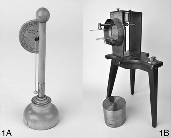
This Adams electrometer in the possession of the Whipple Museum still functions after two and a half centuries, which is a wondrous thing to experience. Usually the functional parts of electrometers were made of very light and fragile materials in order to allow sufficient movement with small amounts of electrical charge. It is a common experience to see gold-leaf electrometers in museums with the crucial gold leaves missing. Adams’s skill in working wood allowed him to make an unusually robust instrument.Footnote 6
However, much as we can admire Adams’s workmanship, what exactly his or others’ electrometers were measuring is not clear. How is the scale on an electrometer calibrated? There were no precise theoretical calculations showing how much deflection of the straw, gold leaf, or Adams’s wooden arm should result from a given amount of charge imparted to an electrometer. Not only was Coulomb’s law of electrostatic attraction and repulsion not yet established (Coulomb’s paper was published in 1785, about ten years after Adams made his instrument), but knowing the inverse-square law is nowhere near enough for actual computations without a lot of additional information about the specifics of the parts of the instrument and its settings. It is difficult to imagine that there would have been consistency of measured values across different instruments, and to use the indications of electrometers in electrical science in a coherent and productive way would have required considerable theoretical savvy and intuition.
Aside from all theoretical considerations, trying to use a simple electroscope, whether it be the original Adams electrometer or a modern toy gold-leaf one, can be a humbling experience. The conceptual simplicity of static electricity imparted by elementary textbooks shows its futility in the face of the practical challenges of the operations of charging, earthing, and insulating. The business of static electricity is not as easy as it might seem in the abstract. Electrometers require a lot of skill and knowledge to build and operate (which those of us with a typical modern scientific education most likely lack). All in all, it seems overdetermined that the numerical readings given by instruments such as the Adams electrometer would not have allowed meaningful arithmetic operations on them, which means that to call them electrometers – measuring tools – as opposed to electroscopes – indicating tools – is clearly a misnomer. Even some of the very early instruments also allowed the measurement of the angle of separation, but that does not constitute an electrical measurement. Indeed, the two terms were used quite interchangeably in the early days. By the late nineteenth century the electrometer had been re-conceived more strictly as a measuring instrument, and what it was now seen to measure was electrical potential; the most iconic example of it was the quadrant electrometer invented by William Thomson (later Lord Kelvin).Footnote 7
So, is the story of the eighteenth-century electrometer one of faux-quantification and tacit knowledge? Yes, but our next ‘exhibit’ (Wh.1353, Figure 7.1, exhibit 1B) reveals another whole layer to the story. Well over a century after Adams built his instrument, electrometers made an unexpected return to cutting-edge research in physics. This gold-leaf electroscope, dated December 1905 and following a design developed by Pierre and Marie Curie, was transferred to the Whipple Museum from the Cavendish Laboratory. The Curie-type electroscope had two gold leaves attached at its top to a brass plate, both hanging together vertically when the instrument was not charged.Footnote 8 As is the case with many gold-leaf electrometers, the delicate gold leaves are missing.
As the association with the Curies suggests, this electroscope was used to measure radioactivity: a radioactive sample placed on the capacitor plate would cause the charge on the electroscope to decrease. Take the description in an educational text in the 1920s by Noah Ernest Dorsey.Footnote 9 First, Dorsey explains, the insulated piece of metal and the attached piece of gold leaf are electrically charged, causing the leaf to deflect away from its normal, vertical position. The position of the leaf is observed by the experimenter peering through a microscope with a ruled scale in its eyepiece. The leaf will gradually lose its charge and move back to its vertical position due to imperfect insulation. The experimenter observes the leaf’s movement and times how long it takes for the leaf to move over a few divisions of the scale, and from this can determine a rate of drift in the leaf when there is no radioactive source present. This process is then repeated, but with a radioactive source placed in the instrument, resulting in a second rate of drift, different from the first due to the ionising radiation causing the electrical charge to dissipate at an increased rate. The ratio of the two drifts indicates the intensity of the radioactive source.Footnote 10 Dorsey follows his basic description with a discussion about further practicalities, including how the instrument should be insulated, whether or not specimens are fully aged, and how corrections should be made for specimens of different sizes.
Typical narratives of progress tend to ignore how old technologies linger on and find other uses, and the Curie electrometer and its use in radioactivity research is an excellent reminder of this. Electroscopes were also required to accurately measure very small quantities of electricity for studies such as C. T. R. Wilson’s investigations into atmospheric electricity.Footnote 11 The gold-leaf electroscope was, then, an instrument that retained its usefulness well over a century after it had first been developed for electrical measurement. Our pairing of electroscopes from 1905 and 1775, both of which work in essentially the same way to indicate the presence of small quantities of electricity, demonstrates that the arrival of new technologies does not necessarily render older technologies redundant.
Galvanometers in the Lab and in the Field
Now let us turn our attention to galvanometers. First of all, there is a gap to be filled in the understanding of most historians of science about how galvanometers work. A very basic education in physics teaches us the fundamental theoretical principle, which goes back to Hans Christian Ørsted’s discovery that a nearby electrical current could turn a compass needle. But there was a very long way to go from that basic electromagnetic connection to making a usable and useful instrument for measuring electrical current. In contrast to the case of electroscopes, in the development of galvanometers the focus on true quantification was very strong, and it was achieved to an impressive degree. In this section we want to start by giving a very brief description of the major steps that were involved in the making of galvanometers, and then show how the desirable configurations depended on the contexts of use. A whole century after Ørsted’s discovery of electromagnetic action, significant improvements were still being made to meet the needs of various users. In the remainder of this chapter we want to give a sense of the character of these improvements that made galvanometers what they were, exhibiting the different developments that were made to suit different needs.
Ørsted’s set-up, as is well known, was a metallic wire placed above (or below) a compass needle (or, more generally speaking, a pivoted bar magnet), initially resting along the direction of the Earth’s magnetic field. When the wire was connected to a battery and current was established in the wire, the magnet was rotated by a certain angle. This is because the current exerted a certain amount of force on the magnet, which would eventually rest where there was equilibrium between the force exerted by the current and the Earth’s magnetic field tending to pull the magnet back to its original position. Johann Schweigger, André-Marie Ampère, Claude Pouillet, and others then did the fundamental experimental and theoretical work, establishing a clear theoretical relation between the angle of deflection and the strength of current.
In order to turn this arrangement into a precise and usable instrument, many major practical steps were needed.Footnote 12 Almost immediately after Ørsted’s work in 1820, researchers noted that wrapping the wire into a loop going around the magnet would double the action on the magnet: a wire placed below the magnet has the opposite direction of effect to a wire placed above the magnet if they both carry current in the same direction, but in a loop of wire the direction of current is opposite above and below, so the effects on the magnet are aligned in the same direction. Now, the description just given would dictate a long rectangular shape of a loop, with negligible effect from the short sides, but in fact the same effect can be achieved with a circular loop, provided that it is much larger than the magnet and the magnet is placed in the middle of the loop, as in the Helmholtz galvanometer we will describe in the next section (exhibit 3A); this is an example of a ‘tangent galvanometer’, so named because ‘the tangent of the angle of its deflection will be nearly proportional to the current passing through the coil’.Footnote 13 The main point, in that configuration, is that the magnet will try to align itself with the magnetic field produced by the loop of current, which points perpendicularly to the plane of the loop. Now, if one makes many turns with one long wire (in other words, one makes a coil), the effect can be multiplied.
Another major line of innovation in galvanometer design was to move beyond the reliance on the Earth’s magnetic field in the regulation of the movement of the magnet. Aside from the obvious inconvenience of needing to place the apparatus in a particular direction in each setting, there was also the problem of interference by other magnetic fields that may be present. This problem was dealt with in two different ways, which gave rise to the development of two major types of galvanometers, namely the moving-magnet and moving-coil types. The moving-coil type rested on a larger innovation in one clear sense: departing from the original paradigm of the rotating compass-needle, a small current-carrying coil was put in the magnetic field of a permanent magnet (often a horseshoe-shaped one, as shown in the next section: exhibit 3B). By employing a permanent magnet of a sufficient strength, the influence of any given external magnetic fields, including that of the Earth, could be made negligible. Whipple credits William Sturgeon with the invention of the moving-coil arrangement as early as 1824, which he used to demonstrate voltaic and thermo-electric currents, and notes an early application of this design to telegraphy in 1856 by Cromwell F. Varley.Footnote 14 Norman Schneider by 1907 thought that the moving-coil galvanometers of the D’Arsonval type ‘had been so perfected that they are being almost universally adopted’.Footnote 15
In the moving-magnet galvanometer, the mechanisms for eliminating the influence of external magnetic fields were more complex. Sometimes one employed a ‘compensating magnet’ that roughly cancelled out the Earth’s magnetic field.Footnote 16 But a real line of innovation began with the so-called astatic needle, which consisted in two magnetic needles fixed together in parallel, one a little distance over the other, with their polarities in opposite directions.Footnote 17 The net force on such a compound needle exerted by a uniform magnetic field would be zero, as the force on one needle would be equal and opposite to the force on the other needle. It would be ‘astatic’ in the sense of having no preferred position where it would rest.Footnote 18 However, in a non-uniform field, the strengths of the forces on the two needles would be different, so there would be a net force. The simplest situation to arrange is as follows: ‘The lower of the magnetic needles is inside the coil which carries the current under test, and alone experiences a torque due to the resulting magnetic field.’Footnote 19 In an arrangement that became common later, the two magnets in an astatic arrangement were placed very far apart so as to minimise the effect of the current to be measured on the ‘outside’ magnet.Footnote 20
Both in the moving-coil galvanometers and in the moving-magnet galvanometers, eliminating the role of the Earth’s magnetic field meant that something else had to act as a spring that prevented the indicating needle from automatically deflecting all the way to 90°, regardless of the strength of the magnetic force from the electrical circuit being tested. Almost universally it was a torsion balance that played this role, a wire or string with which the moving coil would be hung; when twisted, the suspension wire or string would exert a stronger restorative (un-twisting) force the larger the angle of deflection was. The torsion balance was the key apparatus used by Coulomb for his measurements of electrostatic force in his famous work published in 1785, and ever since then it had been available for use in various forms in physical measurements.
Our pairing of instruments from the Whipple Museum in this section illustrates very well the contrasting requirements for a precision instrument designed for scientific research carried out in the well-protected space of a laboratory, and for a robust and reliable indicator fit for use in a workshop or even in the field. They are but two very divergent examples from a profusion of different galvanometers developed in the late nineteenth and early twentieth centuries to meet a variety of needs.Footnote 21 Both of the instruments we have selected are moving-magnet galvanometers, but, as even their external appearances suggest, they were intended for different types of use. A well-situated physics laboratory would ideally be free from vibration and any large moving metal objects that might interfere with the delicate operation of sensitive electrical instruments. In contrast, engineering workshops would often be housed in an industrial building with lots of activity, including large stretches of cable being moved around, which would compromise any delicate readings that were being made.Footnote 22
The first of those instruments, Wh.0939 (Figure 7.2, exhibit 2A), is an example of the most famous type of precision galvanometer, invented in the late 1850s by William Thomson (later Lord Kelvin). It was originally in the context of telegraph signalling that his work on galvanometers began. Thomson’s main objective was to increase the sensitivity of the apparatus. As Silvanus P. Thompson describes in his classic biography of Thomson, ‘He wanted an instrument that would work with a smaller fraction of current. So he determined to lighten the moving part – the suspended magnet – substituting for the heavy needle a minute bit of steel watch-spring (or two or three such bits), which he cemented to the back of a light silvered glass mirror suspended within the wire coil by a single fibre of cocoon silk.’ And then he added an ingenious method of observation, which was ‘directing upon the mirror a beam of light from a lamp, which beam, reflected on the mirror, fell upon a long white card, marked with the divisions of a scale’. The beam of light served ‘as a weightless index of exquisite sensitiveness, magnifying the most minute movements of the “needle”’. Thomson took out a patent for this ‘mirror-galvanometer’ in 1858. It is interesting to note that this instrument, initially designed for field use, later became an indispensable precision instrument for the laboratory. As Thompson puts it, ‘It served not only as a “speaking” instrument for receiving signals, but as an absolutely invaluable appliance both at sea and in the laboratory for the most delicate operations of electric testing.’Footnote 23

The Thomson-type mirror arrangement, which could in fact be used either for a moving-magnet or for a moving-coil galvanometer, reached a very impressive degree of precision. By 1910 John Ambrose Fleming could boast that, ‘In modern mirror galvanometers a deflection of 1 mm of the spot of light upon a scale at 1 metre distance can be produced by a current as small as one hundred millionth (10−8) or even one ten thousand millionth (10−10) of an ampere.’Footnote 24 The sensitivity of the mirror galvanometer recommended it as an instrument of detection, which is what is most needed for the telegraph. But it could also be rigged up as an instrument for precision measurement.
Our instrument (2A), which had been used at the Cavendish Laboratory before being transferred to the Whipple Museum, was made by Elliott Brothers for the British Association Committee on Electrical Standards. Describing it as a ‘very convenient form of Thomson’s galvanometer’, the Encyclopaedia Britannica suggested that ‘such a galvanometer as this, provided with a high and low resistance coil, would meet all the wants of most laboratories’.Footnote 25 The 1864 report of the British Association Committee gives a few details of what it was like to work with this type of galvanometer:
The instrument was placed in a deal box, blackened inside, with large apertures to observe through. The spot of light could thus be clearly seen, and the divisions of the scale were sufficiently illuminated to enable the observer to see immediately in which direction the spot of light moved. The instrument was sufficiently delicate to show 0.001 per cent difference in the ratio of any two nearly equal conductors compared, corresponding to 1/10 millim. on scale of bridge. An ordinary galvanometer was also at hand to find about the place of reading on the scale.Footnote 26
Indeed, this instrument is a delicate tool, beautifully crafted for precision measurement. There are some clues that the instrument could be adjusted in a number of different ways to accommodate the needs of an experiment: extendable brass tubing that made up the frame of the instrument could alter the distance of the scale from the mirror within the galvanometer; levelling feet were incorporated to help the user ensure it was completely horizontal; an adjustable brass slit below the paper scale allowed the user to alter the amount and focus of light being reflected off the mirror; and the resistance coil in the instrument could be swapped for a higher or lower resistance, depending on the measurements being taken. Together with other material features of the instrument, like the ‘single fibre of cocoon silk’ described by Silvanus Thompson in his description of the mirror galvanometers, moving-magnet reflecting galvanometers were delicate instruments. Although, with care, they could be used at sea or in the telegraph office, their value in the laboratory came from the tiny variations in electrical current they could indicate.
In contrast, our second instrument, the ‘Lineman’s Detector’ (Wh.3090, Figure 7.2, exhibit 2B), was commonly used by linemen working in the electrical telegraph industry. An early portable meter, it was designed to be used outdoors for indicating faults and tracing circuits.Footnote 27 In this instrument the galvanometer is housed in a small wooden box, with rounded corners and a metal ring for ease of carrying. The pointer is protected by a small glazed window, though the instrument can be opened up for adjustments, which in this case also reveals a handwritten note of the resistance at 60 °F. It is a simple instrument with an inch-long magnetic needle mounted on a horizontal axis (so that it sits vertically) in the space within two coils that are fixed side-by-side.Footnote 28 It lacks all the delicate controls and shieldings that ensure valid quantitative measurement, but it will easily indicate the presence and direction of a current passing through a circuit element connected up to it.
Telegraph engineers needed to be able to work wherever a fault on the line took them, usually outdoors with only the resources they were able to take to the site to make repairs. As more underground and underwater cables were installed and cable technology improved, new and more sensitive methods were needed to test for current leakage and faults. The galvanometer was a crucial instrument in these tests.Footnote 29 In advance of the 1850 attempt to lay a transatlantic telegraph cable, cables were hung over the side of the ship and tested by connecting a battery and galvanometer across them.Footnote 30 In more everyday situations, telegraph engineers had to tackle a range of faults with cables laid in the ground. Although quantitative measurements became increasingly important as cable technologies became more sophisticated, many of the faults could be discovered with an uncalibrated galvanometer that simply required observation of whether the movement of the needle was more or less ‘strong’. As William Slingo, founder of the Telegraphic School of Science at the General Post Office, wrote with his colleague Arthur Brooker, ‘The lineman’s detector … is a very handy instrument when used for tracing circuits and localising faults, but it must not be regarded as a measuring instrument.’Footnote 31 That is correct, in the same sense that the electrometers and electroscopes discussed above did not really provide quantitative measurements. However, the important point is that laboratory ‘meters’ do not have to be true measuring instruments in order to perform useful functions, including the enabling of other measurements.
Instruments for Teaching versus Research
In this section we wish to draw a comparison and contrast between the use of galvanometers in research and teaching. One preliminary remark we need to make is that there were great changes happening throughout the nineteenth century in the institutional and physical settings in which research and teaching took place. Both teaching and research took place at universities, of course, but there was much else besides. The tradition of industrial research was taking shape, and a small number of non-university institutions such as the Royal Institution maintained their crucial importance.Footnote 32 ‘Amateur’ or ‘private’ researchers working in their ‘spare time’ became gradually less important as the century wore on, but they remained a non-negligible force. We want to highlight one such private researcher, Warren De la Rue (1815–89), who gave various instruments including a galvanometer to the Royal Institution, which then presented it to the Whipple Museum (Wh.1347, Figure 7.3, exhibit 3A).

Figure 7.3 Exhibit 3A: a moving-magnet pointer galvanometer by Elliott Brothers, c. 1880. Exhibit 3B: a moving-coil reflecting galvanometer by the Cambridge Scientific Instrument Company, c. 1902.
De la Rue was born in Guernsey and educated at the Collège Sainte-Barbe in Paris, after which he entered his father’s stationery business in London, and carried out scientific research as an avocation. De la Rue is best remembered now for his pioneering work in the photographing of astronomical objects, but he also carried out interesting and useful research in chemistry and electricity. In the area of electricity, De la Rue’s major contributions included the invention of a platinum-coil light bulb, the investigation of electrical discharges in vacuum tubes, and the silver-chloride battery, which he employed for his other studies.Footnote 33 Starting with the work on the platinum-coil light bulb, which he undertook at a young age in 1840, De la Rue’s electrical research involved high-powered operations using large voltages and currents, in stark contrast to the efforts of William Thomson trying to pick up the very faint telegraph signals coming across the ocean. So it was quite appropriate for De la Rue to employ a moving-magnet tangent galvanometer, which was the instrument of choice for the measurement of high currents. The instrument we have included here was a high-quality but standard-issue Helmholtz-type galvanometer, in which the moving magnet sits in the middle of the instrument, between two coils. This instrument is not unique, but has a few interesting features, including levelling feet, implying it was designed for precision use, and a water-cooling pipe that runs around the coil. Although it was a relatively standard instrument, the uses to which De la Rue turned it were unique to his particular areas of research.
Turning now to the very different context of teaching, the immediate thing to note beyond the academic sphere is the context of trade-based training. When electrical engineering first emerged as a profession, most practitioners using galvanometers and other electrical instruments for their trade learnt about them during a practical apprenticeship. Meanwhile, laboratory-based electrical work was the preserve of a few independent researchers or researchers with university teaching positions.Footnote 34 Equipment and techniques in both lab and field were still becoming established as understanding of electrical theories grew rapidly. Early on, galvanometers were non-standardised and often challenging instruments to calibrate and use well. As discussed above, in the field they were used as indicators or detectors more often than as carefully calibrated measuring devices. As the century progressed formal education became increasingly available for both engineers and scientists, and the debates around what should be taught to each group reflected the newly negotiated roles of each profession. The differing roles are also expressed in the types of instruments and the language used by the two groups. Throughout the early decades of the new profession, electrical engineers could by and large manage with rule-of-thumb calculations, and using galvanometers as indicators. By the 1870s, trade publications like The Telegraphic Journal were advocating that engineering students should use good scientific practice. An 1873 advert for a prize for students stated that
To be awarded to the Author of the best paper on ‘The evidence of the theory of correlation of Physical Forces as applied to Electricity and Magnetism’ … each paper submitted for competition must describe original experiments.Footnote 35
The emphasis on original experiments also suggests a requirement for students to have access to instruments that could measure electrical and magnetic effects. The rhetoric in trade journals in the 1870s repeatedly reinforced the idea, promoted by vocal proponents of technical education, that engineers should think scientifically, and eschew the old ways of doing business:
These words [tension, intensity, and quantity] are daily employed by the majority of those engaged in Telegraphy, and to their use may be attributed, I think, the great want of accuracy in electrical matters displayed by many of this class of men. Nothing is more likely to foster unscientific habits of thought than the constant employment of ill-defined terms.Footnote 36
The education available for telegraph engineers changed dramatically throughout the nineteenth century, reflecting national trends towards awarding qualifications and extending the length of formal study in many professions. The mechanics’ institute movement had begun in the late eighteenth century, and by 1850 there were about 700 mechanics’ institutes teaching a range of subjects, sometimes including electricity, to workmen.Footnote 37 Telegraphy was a large commercial venture, and ensuring that engineering staff were properly trained was an essential part of maintaining the network. Equally, it was important for the telegraph companies to understand the most recent advances in electrical theory in order to improve the network and keep it functioning as well as possible. The availability of instruction manuals and measuring instruments aimed at students grew to meet the demands of the growing numbers of trainee telegraphers and electricians.
By the 1880s, fifty years after William Fothergill Cooke and Charles Wheatstone’s landmark demonstration of a practicable telegraph system, non-university technical education in electricity or telegraphy had become a reality. Training centres such as the Finsbury Technical College in North London and the Central Institution in South Kensington were established. This raised a practical question of what could reasonably be taught in a classroom, especially as many engineers felt that the demands of a full-scale telegraph line could not be adequately replicated on a small scale. A compromise was met when William Ayrton – the same Ayrton whose designs and name are associated with many of the electrical instruments in the Whipple Museum’s collection – was appointed City and Guilds Professor of Physics in 1879. His inaugural address contained an important message: his lectures and laboratory teaching ‘would not compromise the integrity of the workshop as the definitive place for the apprentice to learn his trade’.Footnote 38 The classes, he argued, were not meant to take the place of practical experience, but to supplement it. Students would spend laboratory time with teaching instruments as well as field instruments, learning the principles behind the practical work they would do to keep the telegraph lines running. The classes could serve to shorten the duration of an apprenticeship from the then typical seven years to just four years. Instruction in Ayrton’s classes met with approval from engineers, and covered topics such as the construction of resistance coils, the construction and use of artificial cables, and the use of various kinds of equipment. To better simulate field conditions, ‘artificial lines’ were constructed out of several hundred yards of telegraph cable. Bench equipment was used in some instances to create a proxy for field work and on other occasions to enable individual enquiry and theoretical understanding. Universities also expanded their offer for electrical education. Professor George Carey Foster succeeded in establishing a students’ physical laboratory at University College London as early as 1866, and was instrumental in teaching practical courses on a variety of physical subjects, including the technical training of telegraph engineers.Footnote 39 The arrival of dedicated technical institutes provided specialist practical training in a formal setting that was distinct from natural science teaching. Appropriate scientific instruments were essential for making this work, and equipment like the ‘Outfit for teaching Resistance Thermometry’ (Figure 7.4) demonstrates the market in instruments for teaching that had emerged by the end of the nineteenth century.

In this context, our second instrument in this section, the moving-coil reflecting galvanometer (Wh.4190, Figure 7.3, exhibit 3B, the same type of galvanometer as the one illustrated in Figure 7.4), shows the new market that developed specifically around the education of engineers. This is a student version of the ‘Ayrton–Mather’ galvanometer, described in their 1890 paper on galvanometers for the Philosophical Magazine.Footnote 40 The Ayrton–Mather type of galvanometer featured a metal coil enclosed in a very long narrow tube between the poles of a permanent magnet. The shape of the coil and its position in the magnet made it very sensitive. In this particular example, a glazed window allows the users, perhaps students, to see the coil’s movements. The large horseshoe magnet is not hidden in a case and can be easily viewed.
As in the Thomson-type galvanometer, in the Ayrton–Mather type light was reflected from a mirror to indicate the movement within the instrument, in this case of the long thin coil. The Cambridge Scientific Instrument Company sold this particular model of instrument as a student version bundled with a resistance bridge and resistance thermometer as part of an ‘Outfit for teaching Resistance Thermometry’. In this set-up, the galvanometer itself cost only £3, 15s, though the full outfit including a bridge, galvanometer, resistance thermometer, and cables cost as much as £11, 3s (Figure 7.4).Footnote 41
In the last decades of the nineteenth century, the nature of academic and practical training evolved rapidly as the need for practical training in electrical technologies continued to grow both in the technical colleges and in the universities. Twenty-five years after Foster had been successful in establishing a physics laboratory, UCL decided to indebt itself substantially to build an extension.Footnote 42 The new engineering wing opened in 1893, and contained a lecture room, a large laboratory, and sectioned-off areas including a dynamo room and areas for testing arc lamps and incandescent lamps.Footnote 43 The fact that the university was willing to spend so much money and commit itself to several years of repayment shows how important practical teaching of electrical engineering had become.
The ‘Outfit for teaching Resistance Thermometry’ was produced in Cambridge by the Cambridge Scientific Instrument Company. The foundation of the company in 1881 was timely, following closely behind the opening of the Cavendish Laboratory at the University of Cambridge in 1874. Its arrival, just as technical training for electrical engineers was gaining traction, placed the company in a strong position as supplier to a new and ambitious physical laboratory at a time when electrical engineering was professionalising and growing rapidly.Footnote 44 This goes some way towards explaining the wide range of instruments across the two realms of electrical training held by the Whipple Museum. Apparatus suitable for laboratory research and instruments designed explicitly for teaching both have a place.
Unique versus Standardised Instruments
Our last pairing of instruments illustrates the difference between a standardised instrument and a bespoke piece designed by the user himself. It is not so much that there is an inherent difference between the two types, but more that they represent different phases in the invention of an instrument. And, of course, only some bespoke instruments ever become standardised items, and there will be interesting reasons for why and how that happens.
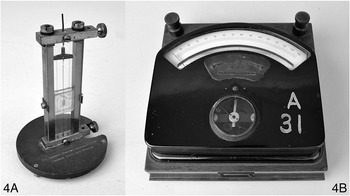
The first instrument in this pair (Wh.4045, Figure 7.5, exhibit 4A) is a thermal reflecting galvanometer, made in 1907 by the Cambridge Scientific Instrument Company. This type of instrument was invented by 1904 by William Du Bois Duddell (1872–1917), who was a student of William Ayrton at the London Central Technical College and would eventually become the President of the Institute of Electrical Engineers in 1912. This instrument was an instance of a thermo-galvanometer, measuring current by the amount of heat it produces in passing through a resistor. Duddell himself gave a detailed account of how he came to design the instrument, which he describes as ‘essentially a very delicate Ayrton–Perry twisted strip-ammeter which has been improved by the addition of a temperature-compensation device to minimize the zero-creep when the temperature of the whole instrument changes’.Footnote 45 Taking up Duddell’s invention, the Cambridge Scientific Instrument Company marketed this instrument, along with a whole range of other instruments designed by him.Footnote 46 The Company’s 1912 catalogue of electrical instruments notes as a special feature of this instrument that it is ‘robust and can be carried about in the pocket’ and advertises that ‘it is easily set up and requires no levelling’.
The cliché that necessity is the mother of invention comes into force clearly in Duddell’s account. First of all, he notes that his concern was to improve instruments for the measurements of alternating currents (AC), which is a completely different game, conceptually and practically, from measuring direct currents (DC). The most common mechanism for AC measurement involved ‘suspending within a coil of insulated wire a small needle of soft iron placed with its axis at an angle of 45° to the axis of the coil’. Or a silver or copper disc could be used instead of the soft iron needle. ‘When an alternating current is passed through the coil, induced currents are set up in the disc and the mutual action causes the disc to endeavour to set itself so that these currents are at a minimum.’ Avoiding the complex electromagnetic interactions involved in such mechanisms, Duddell sought to exploit the heat-generating effects of currents for his AC galvanometers.Footnote 47 After hearing Duddell’s explanations, it is difficult to dispute that the thermal type of galvanometer, based on a fundamentally different principle from the instruments we have discussed above, was the correct choice for AC measurements.
The central element (literally and figuratively) in Duddell’s instrument was a twisted platinum-alloy wire, which was boxed in to have a fixed length.Footnote 48 When current passed and heated this wire, it expanded; yet as it was boxed in and not able to stretch out, it twisted itself more tightly to keep its length constant. When Duddell got down to the business of detailed instrument-design for the twisted-strip instrument, his dominant concerns were range and precision. A small mirror attached to one place on this twisted wire allowed a precise monitoring of the amount of extra twisting caused by the heating, and from this angle measurement the amount of current could be inferred. One can expect that this clever arrangement required a lot of skill and knowledge to operate successfully. An important part of the difficulty to be overcome was the fact that it provided a very indirect measurement involving several steps of inference, each of which opened up room for error and uncertainty. As Duddell explains, what is directly measured in this instrument is the angle of twisting, from which one infers the change of temperature, from which one infers the rate of heat-production in the wire, from which one infers the amount of current passing through the wire. Duddell conceived his main task as obviating the difficulties in thermal galvanometers arising from the ‘fact that what is really measured is a difference of temperature, and not the rate of production of heat’.Footnote 49 He invented two different instruments to meet this challenge, which were consciously designed to serve different purposes. Our exhibit 4A was the first of these.Footnote 50
The second object in this final pair (Wh.2440, Figure 7.5, exhibit 4B) is a portable combined voltmeter and ammeter, manufactured by Siemens. Unlike the Duddell instrument, the working parts of the objects are completely obscured literally by a black box. The user can see a needle that points somewhere on a scale marked up with 150 divisions. A second glazed window reveals a small part of the workings, a pivoted coil surrounding a fixed iron core. There are also terminals to connect the instrument up to a circuit, and accessories to modify the range of the instrument. However, the instrument itself gives away little about how it works. The sturdy and carefully padded wooden box it is packed in, however, suggests a delicate lab instrument rather than something that might be used in the field. The lack of intricate knowledge of the inner workings of the box is an indicator of an important shift that took place in electrical measurement as ‘direct-reading’ instruments were developed. The transition from quantitative instruments that required the user to calculate voltage or current in a manner depending on the specific set-up of the device to an instrument in which the voltage or current was read directly from a dial paved the way for easy-to-use black-box technologies. Direct-reading instruments were initially distrusted by many, with some physicists objecting to ‘ammeters masquerading as measuring devices’. Over time, the utility of the instruments won over many, and black-box technologies became commonplace in labs and the field alike.Footnote 51
As well as varying from exhibit 4A in that this instrument’s workings are obscured, another difference between these two instruments is that we know a great deal about the development of the Duddell instrument, but there is very little to be found in the literature about the development of the Siemens device. What we do know is that this instrument is likely to date from the mid 1920s, on the basis of advertisements for similar models produced by Siemens and Halske AG that appeared in Science magazine between 1923 and 1926. The company produced a few variations on the precision voltmeter in this period for German, British, and American markets, many of which were packaged in the same casing, and with a small subset that also allowed the user to read off current measurements.Footnote 52 The adverts in Science magazine appeal directly to their readership of researchers and laboratory scientists, emphasising the use of the instrument in research laboratories. A slightly different model to the Whipple’s example by Siemens & Halske, a ‘precision Volt-Ammeter with seven ranges’, was marketed as
More than an ordinary Voltmeter or Ammeter. This unique instrument is a combination of voltmeter and ammeter which is so accurate, so permanent in its calibration and so completely compensated for temperature changes that it is used for the precise measurement of current and potential in laboratory work as well as for checking and calibrating other instruments.Footnote 53
This portable box, then, could apparently satisfy everything a laboratory might need in one neat package. Other manufacturers were also bundling different types of electrical measurement into single boxes. A notable example is the AVOmeter, produced by the Automatic Coil Winder and Electrical Equipment Co. in 1923. The A, V, and O stand for ‘amps’, ‘volts’, and ‘ohms’, respectively. The British patent for the instrument, with a priority date of 1922, described the apparatus as follows:
A combined portable electric measuring apparatus is arranged to read current, voltage and resistance on a single moving-coil instrument. Resistances, a battery, and a switch may be arranged in connection with the instrument so that, by means of the switch and without altering the testing leads, the circuits for such measurements may be changed and the sensitiveness of the instrument when used as an ammeter or voltmeter may be varied by shunts or series resistances respectively.Footnote 54
Compared with the high-specification lab equipment being produced and marketed by Siemens, the AVO range was relatively affordable.Footnote 55 The convenience and affordability of what later came to be described as multimeters, the word used in the Whipple Museum catalogue to describe this instrument, made them an indispensable tool. Today they are ubiquitous, used routinely by researchers, electricians, and technicians across virtually any industry that uses electrical or electronic components. However, the technical development of the multimeter, like many of the other rapid developments in electrical technologies in the early twentieth century, passed by relatively unnoticed amid the exciting arrival of entirely new types of technologies. The start of British Broadcasting Company transmissions in late 1922 made ‘listening-in’ a mainstream activity in Britain, an activity that led millions of people to take up home electronics as a hobby. In all of this the multimeter was a useful tool, but one that developed and repackaged existing technologies rather than broke new ground. Consequently, the history of this particular black box, and many other standardised off-the-shelf instruments, remains almost as obscure as its contents.
Learning from Collections
In this chapter we set out to illustrate what can be learnt by closely studying instruments and their contexts. Each of the eight instruments featured embodies some combination of theories, technical advances, user needs, and local, national, or international technical standards. By looking at instruments, their designs, and their users, it is possible to trace the development of new disciplines, techniques, and theoretical advances. For instance, telegraph engineers did not need a measuring device for work in the field, and an indicator like the Lineman’s Detector was sufficient for fault-finding. In the same period, the moving-magnet reflecting galvanometer used in De la Rue’s laboratory had a range of calibration and levelling tools built in and could be used as a sensitive precision measuring tool. Later, engineers working with more sophisticated systems required more refined instruments to keep the network operational. These needs drove an increase in theoretical training, and in turn, the increase in training drove a market in electrical instruments designed for students. As engineers became more adept at applying mathematical rules to their work, portable instruments transitioned from merely indicating electrical current and its direction to providing the ability to directly read measures of current or voltage.
Taking a step back from the individual object and looking at the collection held by the Whipple Museum and other museums can also prove fruitful. There is a tendency in museum collections of scientific instruments towards the pristine and apparently (or actually) unused. This is despite the argument made by Simon Schaffer, among others, that instruments are prone to faults and failure by nature: ‘Faults are defaults, yet instruments perform’; however, ‘states of disrepair are often not deemed worthy of display, even though – perhaps because – they show signs of use.’Footnote 56 The ambition to collect the pristine is made plain in catalogue descriptions. Many of the instruments in the Whipple Museum collection have been catalogued with notes drawing attention to their incompleteness – ‘lacking zero-adjustment screw’ (Wh.4269); ‘glass broken when packing’ (Wh.4316); ‘lacking wooden case’ (Wh.4240); or ‘lacking post and controlling magnet’ (Wh.1333). The need to include absent parts of an instrument in the new identities of instruments when they are added to a museum catalogue shifts the focus away from the objects’ biographies – the means by which they were used, stored, and ultimately added to the museum collection – and instead highlights the partial nature of the object. These nods to wished-for perfection are not reflective of real-world usage of instruments.
There is an asymmetry in catalogue descriptions of instruments that have reached the collection unscathed. Wh.4292 is a moving-coil reflecting galvanometer, given to the Museum by the Cambridge Scientific Instrument Company in 1974. The instrument’s appearance is brassy and polished, suggesting that this particular object was a ‘masterpiece’, produced by a craftsman for the company as the final assessed piece of work at the end of their apprenticeship. Unlike many of the other reflecting galvanometers in the collection, this example still has its delicate and easily lost mirror, quite probably because it was never used. The object catalogue describes the technical details of the instrument but says nothing of its pristine appearance; the cataloguer seems to have assumed by default that this is the ‘normal’ state of the object. If ‘mint condition’ is the preferred state of an instrument collected for a museum’s collection, what reasons might induce a curator to add an incomplete specimen to the collection? Wh.0939 (our exhibit 2A) is a moving-magnet reflecting galvanometer, an instrument ‘lacking [its] suspended system’.Footnote 57 The instrument features in our story, perhaps, for the same reason it features in the Whipple Museum collection. It was constructed by Elliott Brothers for the British Association Committee on Electrical Standards. Aside from its technical qualities, which would meet the requirements of most laboratories in the 1870s, this instrument was an important witness to the establishment of electrical standards.
All objects and collections offer, like historical texts, partial accounts and insights with inherent biases built into what has been collected, how the objects have been described, and the types of categories they have been placed in. Understanding the contexts of collection is vital in order to identify gaps and value-laden qualities in the collection and its supporting body of data. The contexts and biases of collections can be quite different from those of the written texts that, in principle, would be expected to cover similar ground. That means that they can challenge the narratives that are found in textual sources. For example, the presence of the Siemens volt- and ammeter in the collection provides evidence, hard to find in the written record, of the emergence of convenient instruments that performed multiple types of electrical measuring. Because of the role of the Cambridge Instrument Company in helping to build the collections of the Whipple Museum, and the Company’s arrival just as the electrical engineering industry was coming of age and a brand new, ambitious physical science laboratory was becoming established in Cambridge, the range of objects in the Museum’s collection is diverse and captures everyday instruments that were not written about extensively at the time they were developed. In choosing the four pairings in this chapter we sought to present narratives that revealed particular technical and social aspects of the development of galvanometers. However, they also represent a greater whole – the hundreds of electrical and magnetic instruments cared for by the Whipple Museum. Each of those objects has its own story, but by stepping back and looking at the whole collection we begin to see that those detailed investigations of the developments inside individual black boxes also allow us to explore the ways in which, over the course of more than a century, the galvanometer became an embedded and almost invisible part of scientific and technical practice.


 Open access