Refine search
Actions for selected content:
5487 results in Thermal-fluids engineering
Chapter 4 - Energy and Energy Transfer
-
- Book:
- Thermodynamics
- Published online:
- 30 November 2020
- Print publication:
- 27 February 2020, pp 196-253
-
- Chapter
- Export citation
Chapter 6 - Second Law of Thermodynamics and Some of Its Consequences
-
- Book:
- Thermodynamics
- Published online:
- 30 November 2020
- Print publication:
- 27 February 2020, pp 317-353
-
- Chapter
- Export citation
Chapter 8 - Thermal-Fluid Analysis of Steady-Flow Devices
-
- Book:
- Thermodynamics
- Published online:
- 30 November 2020
- Print publication:
- 27 February 2020, pp 452-524
-
- Chapter
- Export citation
Chapter 5 - First Law of Thermodynamics
-
- Book:
- Thermodynamics
- Published online:
- 30 November 2020
- Print publication:
- 27 February 2020, pp 254-316
-
- Chapter
- Export citation
Brief Contents
-
- Book:
- Thermodynamics
- Published online:
- 30 November 2020
- Print publication:
- 27 February 2020, pp vii-vii
-
- Chapter
- Export citation
Index
-
- Book:
- Thermodynamics
- Published online:
- 30 November 2020
- Print publication:
- 27 February 2020, pp 864-872
-
- Chapter
- Export citation
Conversion Factors
-
- Book:
- Thermodynamics
- Published online:
- 30 November 2020
- Print publication:
- 27 February 2020, pp xxvii-xxviii
-
- Chapter
- Export citation

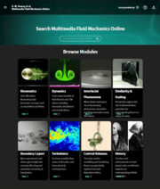
Multimedia Fluid Mechanics Online
- Site License
-
- Published online:
- 27 September 2019
Contents
-
- Book:
- Chemical Kinetics in Combustion and Reactive Flows
- Published online:
- 16 August 2019
- Print publication:
- 22 August 2019, pp ix-xii
-
- Chapter
- Export citation
3 - Software Tools for the Support of Calculation of Combustion and Reacting Flows
- from Part I - Basic Components of Chemical Nonequilibrium Models
-
- Book:
- Chemical Kinetics in Combustion and Reactive Flows
- Published online:
- 16 August 2019
- Print publication:
- 22 August 2019, pp 95-204
-
- Chapter
- Export citation
Part III - Simulation of Combustion and Nonequilibrium Flows in Propulsion and Power Generation Systems
-
- Book:
- Chemical Kinetics in Combustion and Reactive Flows
- Published online:
- 16 August 2019
- Print publication:
- 22 August 2019, pp 281-396
-
- Chapter
- Export citation
Part II - Mathematical Modeling of Selected Typical Modes of Combustion
-
- Book:
- Chemical Kinetics in Combustion and Reactive Flows
- Published online:
- 16 August 2019
- Print publication:
- 22 August 2019, pp 205-280
-
- Chapter
- Export citation
Acknowledgments
-
- Book:
- Chemical Kinetics in Combustion and Reactive Flows
- Published online:
- 16 August 2019
- Print publication:
- 22 August 2019, pp xix-xx
-
- Chapter
- Export citation
Index
-
- Book:
- Chemical Kinetics in Combustion and Reactive Flows
- Published online:
- 16 August 2019
- Print publication:
- 22 August 2019, pp 418-422
-
- Chapter
- Export citation
Preface
-
- Book:
- Chemical Kinetics in Combustion and Reactive Flows
- Published online:
- 16 August 2019
- Print publication:
- 22 August 2019, pp xiii-xviii
-
- Chapter
- Export citation
1 - Approaches to Combustion Simulation
- from Part I - Basic Components of Chemical Nonequilibrium Models
-
- Book:
- Chemical Kinetics in Combustion and Reactive Flows
- Published online:
- 16 August 2019
- Print publication:
- 22 August 2019, pp 3-40
-
- Chapter
- Export citation
4 - Laminar Premixed Flames: Simulation of Combustion in the Flame Front
- from Part II - Mathematical Modeling of Selected Typical Modes of Combustion
-
- Book:
- Chemical Kinetics in Combustion and Reactive Flows
- Published online:
- 16 August 2019
- Print publication:
- 22 August 2019, pp 207-227
-
- Chapter
- Export citation
5 - Droplets and Particles: Evaporation in High-Temperature Flow and Combustion in Boundary Layers
- from Part II - Mathematical Modeling of Selected Typical Modes of Combustion
-
- Book:
- Chemical Kinetics in Combustion and Reactive Flows
- Published online:
- 16 August 2019
- Print publication:
- 22 August 2019, pp 228-261
-
- Chapter
- Export citation
Nomenclature
-
- Book:
- Chemical Kinetics in Combustion and Reactive Flows
- Published online:
- 16 August 2019
- Print publication:
- 22 August 2019, pp xxi-xxvi
-
- Chapter
- Export citation
Dedication
-
- Book:
- Chemical Kinetics in Combustion and Reactive Flows
- Published online:
- 16 August 2019
- Print publication:
- 22 August 2019, pp vii-viii
-
- Chapter
- Export citation
