


1. Introduction
In the realm of medical robotics, the precision and dexterity enabled by robotic systems have revolutionized the approach to minimally invasive surgeries [Reference Zidane, Khattab, Rezeka and El-Habrouk1]. There is a growing emphasis on automating surgical subtasks to enhance surgical efficiency and patient outcomes. Among these tasks, soft tissue manipulation remains particularly challenging due to its inherent complexity and critical impact on surgical success. In recent years, the trend toward more intelligent and autonomous robotic-assisted surgery has led to increased research attention on the automation of delicate sub-procedures, including tissue grasping, retraction, and repositioning [Reference Eugster, Merlet, Gerig, Cattin and Rauter2]. The ability of robots to reliably and safely manipulate soft tissues is fundamental for expanding the range of procedures that can benefit from automation. However, the successful realization of such capabilities is hindered by the intricate, highly nonlinear, and patient-specific mechanical properties of biological tissues, which differ significantly from the rigid objects commonly handled in industrial robotics [Reference Marwan, Chua and Kwek3].
From repositioning organs for improved access to precise procedures such as tumor excision [Reference McKinley, Garg, Sen, Gealy, McKinley, Jen, Guo, Boyd and Goldberg4] and tissue retraction [Reference Attanasio, Scaglioni, Leonetti, Frangi, Cross, Biyani and Valdastri5], accurate handling of deformable tissues is essential to avoid damage and ensure optimal patient outcomes. However, the unstructured nature of soft tissues, coupled with their nonlinear and dynamic behavior, poses significant challenges to achieving autonomous and reliable manipulation [Reference Zhu, Cherubini, Dune, Navarro-Alarcon, Alambeigi, Berenson, Ficuciello, Harada, Kober, Li, Pan, Yuan and Gienger6]. Furthermore, in clinical practice, surgeons rely on a combination of visual feedback, tactile sensation, and deep anatomical knowledge to intuitively select grasping points and modulate force application. Replicating this expert intuition in a robotic system requires not only advanced sensing and perception but also efficient computational models capable of predicting tissue response in real time. The integration of modern sensing modalities – such as depth cameras and force sensors [Reference Muscolo and Fiorini7] – has improved the perception of tissue state, yet the translation from perception to optimal manipulation strategies remains non-trivial.
Traditional approaches to tissue manipulation often rely on predetermined grasping points [Reference Shin, Ferguson, Pedram, Ma, Dutson and Rosen8], [Reference Makiyeh, Chaumette, Marchal and Krupa9], [Reference Yang, Lu, Chen, Zhong and Liu10]. While effective in controlled settings, these methods lack adaptability and do not account for the unique mechanical properties of individual tissues. In robotic-assisted surgeries, the ability to dynamically determine optimal grasping points is crucial, as deformation behavior is intimately linked to the locations where external forces are applied. Surgeons intuitively select grasping points based on their understanding of motion-deformation relationships. Replicating this intuition in robotic systems, however, remains a complex problem, as it requires explicitly modeling the intricate coupling between tissue deformation and applied forces [Reference Golahmadi, Khan, Mylonas and Marcus11].
Recent advances in optimization-based planning, particularly those leveraging the finite element method (FEM) [Reference Fonkoua, Chaumette and Krupa12], [Reference Du, Xu, Ren, Yu and Lu13], [Reference Deng, Ahmad, Xiong and Xia14], have shown promise for capturing the mechanical coupling between grasping points and tissue deformation. By formulating the grasping point selection as an optimization problem, these methods can move beyond heuristic or purely geometric approaches, offering the potential for greater accuracy and adaptability. Nevertheless, most existing methods either focus on forward deformation prediction or are computationally intensive, limiting their practicality for real-time, multi-point grasping in surgery.
In this paper, we present an efficient grasping point selection framework that addresses these limitations. We formulate the deformation task as an optimization problem based on inverse FEM, where optimal grasping points are computed by solving a quadratic programming (QP) problem. Our main contributions are as follows:
-
1. We formulate the grasping point selection problem as a unified QP optimization based on the inverse FEM, enabling the simultaneous identification of multiple optimal grasping points in a single step while explicitly considering the mechanical coupling within soft tissue structures.
-
2. Our framework flexibly supports both sparse key points and dense point cloud inputs, allowing the method to be applied to a wide range of tissue manipulation scenarios without requiring major modifications to the algorithm.
-
3. The proposed method is comprehensively validated in both simulation and real-world experiments. Results demonstrate that our approach achieves high accuracy and strong sim-to-real transferability, outperforming traditional distance-based methods in various challenging tasks.
Figure 1 shows the experimental setup for the proposed method.
Illustration of the manipulation task and grasping point selection. Optimal grasping points lead to task completion while random grasping points lead to failure. The workflow of the proposed method is shown next to the figure.

2. Related work
2.1. Deformable tissue manipulation
Robotic manipulation of deformable tissues is a fundamental yet challenging problem in surgical automation, due to the nonlinear and highly coupled mechanical properties of soft tissues. Model-based methods, such as those utilizing FEMs or mass-spring models, aim to capture the physical behavior of tissues for planning and control purposes [Reference Sahari and Hou15], [Reference Sanchez, Dine, Corrales, Bouzgarrou and Mezouar16]. FEM has become particularly prominent due to its ability to accurately model large 3D deformations of soft materials. However, most model-based studies focus on deformation prediction and control, while the problem of grasping point selection remains under-explored. Specifically, few works have formulated the grasping point estimation as an optimization problem that directly leverages the mechanical coupling between applied forces and desired deformations.
Model-free approaches, including imitation learning and reinforcement learning (RL), learn manipulation strategies directly from data or demonstrations [Reference Salhotra, Liu, Dominguez-Kuhne and Sukhatme17], [Reference Scheikl, Tagliabue, Gyenes, Wagner, Dall’Alba, Fiorini and Mathis-Ullrich18]. While these methods have shown promise in handling high-dimensional and complex manipulation tasks, they generally require large volumes of training data and suffer from limited adaptability to varying tissue geometries and mechanical properties. Moreover, their ability to achieve precise and real-time deformation control is often constrained by the complexity of the learning process and the lack of explicit physical modeling.
2.2. Grasp planning
Grasp planning is crucial for robotic manipulation since it ensures that robots can achieve stable and effective grasps [Reference Yan, Deng, Chen, Nie and Zhang19], [Reference Dong and Zhang20], which are fundamental for executing complex tasks such as assembly, surgery, and human–robot collaboration. Existing methods for grasping point selection can be broadly categorized into assessment-based and distance-based approaches. Assessment-based methods evaluate grasping quality across a set of candidate points using various indices, such as deformation energy, stress distribution, or control effort [Reference Xu, Danielczuk, Ichnowski, Mahler, Steinbach and Goldberg21], [Reference Song, Ramón and Mezouar22]. For instance, Patil et al. [Reference Patil and Alterovitz23] proposed a model-based sampling method that computes deformation energy and maximum stress to determine optimal grasping points for tissue retraction. Han et al. [Reference Han, Zhang and Wang24] developed an optimization-based strategy that integrates contact stability and operational effectiveness indices to ensure efficient deformation control. Although these methods achieve high accuracy, they are computationally expensive, as they require evaluating all possible grasping points, making them impractical for real-time applications.
On the other hand, distance-based methods reduce computational complexity by selecting grasping points based on geometric criteria, such as the largest displacement between initial and target shapes [Reference Thach, Cho, Kuntz and Hermans25]. Nadon et al. [Reference Nadon and Payeur26], [Reference Nadon and Payeur27] developed a selection method by analyzing the difference between the initial and desired contours in polar coordinates, selecting grasping points at locations with maximum contour differences. Nevertheless, this approach fails when multiple grasping points are required. To address this, Huang et al. [Reference Huang and Au28] proposed a task-oriented metric that incorporates both distance and directional factors. This metric evaluates the grasping effectiveness by integrating the grasp’s influence along the deformation path of the object. For dual-arm grasping tasks, the method first identifies two key points based on the extent of deformation and their relative positions. The algorithm is then applied separately to each key point to determine the optimal grasping points. However, distance-based methods overlook the complex mechanical coupling of the tissue structure and may fail in multi-point grasping scenarios or require the implementation of multi-stage planning.
Additionally, RL has been explored for tissue manipulation, where physical simulators are used to train policies for selecting grasping points. For instance, Ou et al. [Reference Ou and Tavakoli29] and He et al. [Reference He, Zhang, Chu, Jia, Yu and Ouyang30] employed RL-based methods to identify optimal grasping points by minimizing control displacement and other matrices. However, these approaches often require extensive training and face challenges in handling complex deformation behaviors, making them computationally expensive.
3. Forward modeling of deformable objects
In this section, we first introduce the discrete-time kinematic equation of soft tissue based on real-time FEM [Reference Coevoet, Morales-Bieze, Largilliere, Zhang, Thieffry, Sanz-Lopez, Carrez, Marchal, Goury, Dequidt and Duriez31]. With the assumption that the tissue manipulation is conducted at relatively low velocities, therefore, we can model the tissue with quasi-static equations. The equilibrium equations are then projected into a constraint space to enable real-time computation. Lastly, the inverse simulation is formulated as a QP optimization problem.
Let
 $\mathbf{x} \in \mathbb{R}^n$
denote the configuration of the object, where
$\mathbf{x} \in \mathbb{R}^n$
denote the configuration of the object, where
 $n$
represents the degrees of freedom. The equilibrium equations of the system at the
$n$
represents the degrees of freedom. The equilibrium equations of the system at the
 $(k+1)$
th sampling time can be described by:
$(k+1)$
th sampling time can be described by:
 \begin{equation} \mathbf{M}(\mathbf{x}_{k+1}) \dot {\mathbf{v}}_{k+1} = \mathbf{p}_{k+1} - \mathbf{f}(\mathbf{x}_{k+1},\mathbf{v}_{k+1}) + \mathbf{u}_{k+1} \end{equation}
where
 $\mathbf{x} \in \mathbb{R}^n$
and
$\mathbf{x} \in \mathbb{R}^n$
and
 $\mathbf{v} \in \mathbb{R}^n$
are the vectors of generalized degrees of freedom (displacement and velocity of the nodes in a mesh);
$\mathbf{v} \in \mathbb{R}^n$
are the vectors of generalized degrees of freedom (displacement and velocity of the nodes in a mesh);
 $\mathbf{M} \in \mathbb{R}^{n \times n}$
is the diagonal mass matrix.
$\mathbf{M} \in \mathbb{R}^{n \times n}$
is the diagonal mass matrix.
 $\mathbf{p}$
and
$\mathbf{p}$
and
 $\mathbf{f}$
are respectively the vectors of external (i.e. gravity) and internal forces;
$\mathbf{f}$
are respectively the vectors of external (i.e. gravity) and internal forces;
 $\mathbf{u}$
denotes the external force from the manipulator and can be written as
$\mathbf{u}$
denotes the external force from the manipulator and can be written as
 $\mathbf{H}_g^T \boldsymbol{\lambda }_g$
, where
$\mathbf{H}_g^T \boldsymbol{\lambda }_g$
, where
 $\mathbf{H}_g$
is the mapping matrix between nodes and directions of grasping forces, and
$\mathbf{H}_g$
is the mapping matrix between nodes and directions of grasping forces, and
 $\boldsymbol{\lambda }_g \in \mathbb{R}^{M \times 3}$
is the contribution vector of grasping forces with
$\boldsymbol{\lambda }_g \in \mathbb{R}^{M \times 3}$
is the contribution vector of grasping forces with
 $M$
being the number of grasping points. Since the deformation control is conducted at a relatively low velocity, we thus consider the system in a quasi-static condition. (1) can be rewritten as,
$M$
being the number of grasping points. Since the deformation control is conducted at a relatively low velocity, we thus consider the system in a quasi-static condition. (1) can be rewritten as,
 \begin{equation} \mathbf{p}_{k+1} - \mathbf{f}(\mathbf{x}_{k+1}) + \mathbf{H}^T_g(\mathbf{x}_{k+1}) \boldsymbol{\lambda }_{g,k+1} = \mathbf{0} \end{equation}
The internal forces
 $\mathbf{f}(\mathbf{x})$
are non-linear, we then use a Taylor series expansion to
$\mathbf{f}(\mathbf{x})$
are non-linear, we then use a Taylor series expansion to
 $\mathbf{f}(\mathbf{x})$
and obtain a first-order approximation at a time step
$\mathbf{f}(\mathbf{x})$
and obtain a first-order approximation at a time step
 $(k+1)$
,
$(k+1)$
,
 \begin{equation} \mathbf{f}(\mathbf{x}_{k+1}) = \mathbf{f}(\mathbf{x}_{k}) + \frac {\partial \mathbf{f}(\mathbf{x}_{k})}{\partial \mathbf{x}_{k}} d\mathbf{x}_{k} \end{equation}
where
 $\frac {\partial f(\mathbf{x}_k)}{\partial \mathbf{x}_k}$
can be expressed by the stiffness matrix
$\frac {\partial f(\mathbf{x}_k)}{\partial \mathbf{x}_k}$
can be expressed by the stiffness matrix
 $\mathbf{K}_k$
,
$\mathbf{K}_k$
,
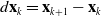 $d\mathbf{x}_k = \mathbf{x}_{k+1} - \mathbf{x}_k$
.
$d\mathbf{x}_k = \mathbf{x}_{k+1} - \mathbf{x}_k$
.
While controlling the whole set of vertices of the object, the problem can be intractable and redundant. To reduce the dimension of the problem, we select a set of feature points on the surface of the mesh to represent the deformation. Figure 2 illustrates the definition of points. The position vectors of grasping points and feature points are then defined as
 $\boldsymbol{\delta }_g$
and
$\boldsymbol{\delta }_g$
and
 $\boldsymbol{\delta }_f$
, respectively. Combining (2) and (3), the equilibrium equation of soft tissue at each step can be established. To perform the modeling in real-time, the problem is projected in the constraint space using the Schur complement:
$\boldsymbol{\delta }_f$
, respectively. Combining (2) and (3), the equilibrium equation of soft tissue at each step can be established. To perform the modeling in real-time, the problem is projected in the constraint space using the Schur complement:
 \begin{equation} \boldsymbol{\delta }_{f,k+1} = \mathbf{W}_{fg}(\mathbf{x}_k)\boldsymbol{\lambda }_{g,k} + \boldsymbol{\delta }_{f,k}^{free} \end{equation}
 \begin{equation} \boldsymbol{\delta }_{g,k+1} = \mathbf{W}_{gg}(\mathbf{x}_k)\boldsymbol{\lambda }_{g,k} + \boldsymbol{\delta }_{g,k}^{free} \end{equation}
Illustration of point definition. The points depicted on the object are nodes of the volumetric mesh of the 3D object. The blue points are nodes attached to the gripper, the green points are the feature points, and the red points are static.

where
 $\mathbf{W}_{ij}(\mathbf{x}_{k}) = \mathbf{H}_i(\mathbf{x}_{k+1}) \mathbf{K}^{-1}(\mathbf{x}_{k}) \mathbf{H}_j^T(\mathbf{x}_{k+1}) \ (i,j = f,g )$
.
$\mathbf{W}_{ij}(\mathbf{x}_{k}) = \mathbf{H}_i(\mathbf{x}_{k+1}) \mathbf{K}^{-1}(\mathbf{x}_{k}) \mathbf{H}_j^T(\mathbf{x}_{k+1}) \ (i,j = f,g )$
.
 $\boldsymbol{\delta }_{f,k}^{free}$
and
$\boldsymbol{\delta }_{f,k}^{free}$
and
 $\boldsymbol{\delta }_{g,k}^{free}$
are respectively position vectors of feature points and grasping points when
$\boldsymbol{\delta }_{g,k}^{free}$
are respectively position vectors of feature points and grasping points when
 $\boldsymbol{\lambda }_{g} = 0$
. With
$\boldsymbol{\lambda }_{g} = 0$
. With
 $\mathbf{W}_{fg}$
, we can measure the mechanical coupling between feature points and grasping points, and with
$\mathbf{W}_{fg}$
, we can measure the mechanical coupling between feature points and grasping points, and with
 $\mathbf{W}_{gg}$
, the coupling between grasping points.
$\mathbf{W}_{gg}$
, the coupling between grasping points.
With the continuity assumption of
 $\mathbf{W}_{fg}(\mathbf{x}_{k+1}) \approx \mathbf{W}_{fg}(\mathbf{x}_{k})$
, (4) can be simplified as
$\mathbf{W}_{fg}(\mathbf{x}_{k+1}) \approx \mathbf{W}_{fg}(\mathbf{x}_{k})$
, (4) can be simplified as
 \begin{equation} \boldsymbol{\delta }_{f,k+1} = \boldsymbol{\delta }_{f,k} + \mathbf{W}_{fg}(\mathbf{x}_k) \Delta \boldsymbol{\lambda }_{g,k+1} \end{equation}
 \begin{equation} \boldsymbol{\delta }_{g,k+1} = \boldsymbol{\delta }_{g,k} + \mathbf{W}_{gg}(\mathbf{x}_k) \Delta \boldsymbol{\lambda }_{g,k+1} \end{equation}
where
 $\Delta \boldsymbol{\lambda }_{g,k} = \boldsymbol{\lambda }_{g,k+1} - \boldsymbol{\lambda }_{g,k}$
. As the grasping point is controlled in position, the change in displacement leads to the motion of feature points by
$\Delta \boldsymbol{\lambda }_{g,k} = \boldsymbol{\lambda }_{g,k+1} - \boldsymbol{\lambda }_{g,k}$
. As the grasping point is controlled in position, the change in displacement leads to the motion of feature points by
 \begin{equation} \Delta \boldsymbol{\delta }_{f,k} = \underbrace {\mathbf{W}_{fg}\mathbf{W}_{gg}^{-1}}_{\mathbf{J}} \Delta \boldsymbol{\delta }_{g,k} \end{equation}
where
 $\mathbf{J}$
is the deformation Jacobian that provides a mapping between grasping point motions and feature point displacements and is updated at each time step.
$\mathbf{J}$
is the deformation Jacobian that provides a mapping between grasping point motions and feature point displacements and is updated at each time step.
Finally, the configuration of the soft tissue for the forward FEM simulation is updated at
 $(k+1)$
th time step by
$(k+1)$
th time step by
 \begin{equation} \mathbf{x}_{k+1} = \mathbf{x}_{k} + \mathbf{K}_k^{-1} \mathbf{H}_g^T \Delta \boldsymbol{\lambda }_{g,k} \end{equation}
Remark. The compliance matrices
 $\mathbf{W}_{fg}$
and
$\mathbf{W}_{fg}$
and
 $\mathbf{W}_{gg}$
cannot be pre-computed because their values depend on the positions of all nodes (the configuration of the tissue) so they change at each iteration. Based on the fact that the soft materials have slow dynamics and are not subject to high-frequency external loads, we assume that the matrices
$\mathbf{W}_{gg}$
cannot be pre-computed because their values depend on the positions of all nodes (the configuration of the tissue) so they change at each iteration. Based on the fact that the soft materials have slow dynamics and are not subject to high-frequency external loads, we assume that the matrices
 $\mathbf{W}_{fg}$
and
$\mathbf{W}_{fg}$
and
 $\mathbf{W}_{gg}$
are constant between two neighboring time steps.
$\mathbf{W}_{gg}$
are constant between two neighboring time steps.
Remark. The tangent stiffness matrix
 $\mathbf{K}$
is positive definite when the robot is constrained to have no rigid body motion. By on different nodes of the FEM or with different directions, there will be no linear dependency between lines of
$\mathbf{K}$
is positive definite when the robot is constrained to have no rigid body motion. By on different nodes of the FEM or with different directions, there will be no linear dependency between lines of
 $\mathbf{H}_f$
and
$\mathbf{H}_f$
and
 $\mathbf{H}_g$
so that the matrices
$\mathbf{H}_g$
so that the matrices
 $\mathbf{W}_{gg}$
is positive-definite and
$\mathbf{W}_{gg}$
is positive-definite and
 $\mathbf{W}_{fg}$
is generally full row rank when the number of lines in
$\mathbf{W}_{fg}$
is generally full row rank when the number of lines in
 $\mathbf{H}_f$
is smaller than the number of lines in
$\mathbf{H}_f$
is smaller than the number of lines in
 $\mathbf{H}_g$
, and
$\mathbf{H}_g$
, and
 $\mathbf{W}_{fg}$
is full column rank in the opposite case.
$\mathbf{W}_{fg}$
is full column rank in the opposite case.
4. Methodology
In this section, we first present the details of the proposed method. Then, we introduce the definition of different cases of inputs: 1) key points and 2) 3D shape point cloud. Lastly, we present the details of inverse FEM and the grasping point selection algorithm.
4.1. Overview of proposed method
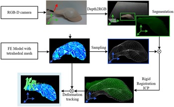
The proposed method consists of three main steps, as shown in Fig. 3. First, the deformable object is represented as a mesh, which can be reconstructed from medical images. The process of reconstructing mesh from medical images is shown in Fig. 4. We obtain volumetric imaging and segment the target organ using semi-automatic thresholding and region growing in 3D Slicer. The segmentation is converted to a triangular surface with marching cubes, smoothed and resampled, and then tetrahedralized in Gmsh to produce the FEM mesh. A finite element (FE) model is then constructed based on the mesh using tetrahedral elements, providing a foundation for real-time deformation simulation.
The overall workflow of the proposed method.

The workflow of mesh reconstruction.

Then, the desired deformation is specified by the input of key points case (IOK) or shape point cloud (IOS). For IOK, the locations of key points are assumed to be known, and the closest vertices on the mesh are selected as feature points. For IOS, a point cloud of the target deformation is captured and aligned with the FE model using a 3D deformation registration method, ensuring consistency between the input and the simulation framework.
Finally, the optimal grasping points are identified by solving a QP problem, which leverages the inverse FEM model to minimize feature errors while accounting for mechanical coupling between grasping and feature points. Unlike prior work relying on heuristic metrics, this formulation allows for the simultaneous identification of multiple grasping points without requiring multi-stage planning. By dynamically considering the mechanical properties of the tissue and supporting both discrete feature points and shape inputs, the proposed method provides a unified and flexible framework for tasks with both single and multiple grasping points.
4.2. Determination of feature points location
To solve (11), it is essential to determine
 $\boldsymbol{\delta }_f^r$
. This paper addresses two types of manipulation tasks: point manipulation and shape manipulation, corresponding to inputs as discrete key points and 3D shape point clouds, respectively. The process of determining feature points for each case is outlined as follows:
$\boldsymbol{\delta }_f^r$
. This paper addresses two types of manipulation tasks: point manipulation and shape manipulation, corresponding to inputs as discrete key points and 3D shape point clouds, respectively. The process of determining feature points for each case is outlined as follows:
4.2.1. Points as input
For tasks where discrete key points are used as input, their locations are assumed to be predefined or directly measurable. We can obtain the positions by visual tracking of key points on the tissue surface. These feature points are often derived from geometric or anatomical markers, commonly used in planar tissue manipulation tasks [Reference Shin, Ferguson, Pedram, Ma, Dutson and Rosen8]. Once the desired feature point locations are given, the closest vertices on the surface of the FE mesh are selected as the feature points. This ensures that the desired deformation can be effectively represented within the finite element framework.
Deformation registration scheme to register the desired 3D shape with the FE model in simulation. Feature points are evenly selected from the surface. Initial feature locations and deformed feature locations are shown in orange and yellow dots, respectively.

4.2.2. Point cloud as input
For tasks involving 3D shape manipulation, the desired deformation is provided as a dense point cloud of the target shape. However, since there is no direct correspondence between the input point cloud and the feature points on the FE mesh, a 3D deformation registration process [Reference Petit, Lippiello, Fontanelli and Siciliano32] is employed to determine the desired feature locations. The procedure is shown in Fig. 5. Specifically, the point cloud of the target shape is captured using a depth camera and segmented using a color-based region-growing algorithm. The segmented point cloud is aligned with the FE model through rigid registration by an Iterative Closest Point method to ensure consistency between the physical object and the simulation.
Let
 $Y = \{y_j\}_{j=1}^{N_y}$
be the set of vertices of the captured deformed point cloud after alignment and
$Y = \{y_j\}_{j=1}^{N_y}$
be the set of vertices of the captured deformed point cloud after alignment and
 $X = \{x_j\}_{j=1}^{N_x}$
the mesh vertices at the current time step. We first conduct a K-Nearest Neighbor searching algorithm to find the correspondences from mesh to point and point to mesh, respectively. By doing this, we can obtain the nearest neighbors from
$X = \{x_j\}_{j=1}^{N_x}$
the mesh vertices at the current time step. We first conduct a K-Nearest Neighbor searching algorithm to find the correspondences from mesh to point and point to mesh, respectively. By doing this, we can obtain the nearest neighbors from
 $X$
to
$X$
to
 $Y$
(
$Y$
(
 $P_X = \{NN_Y(x_j)|x_j \in X\}$
) and from
$P_X = \{NN_Y(x_j)|x_j \in X\}$
) and from
 $Y$
to
$Y$
to
 $X$
(
$X$
(
 $P_Y = \{NN_X(y_j)|y_j \in Y\}$
). The resulting virtual forces, computed based on the weighted distances between corresponding points [Reference Petit, Lippiello, Fontanelli and Siciliano32], are applied to the FE model to deform it iteratively, yielding the desired feature point locations
$P_Y = \{NN_X(y_j)|y_j \in Y\}$
). The resulting virtual forces, computed based on the weighted distances between corresponding points [Reference Petit, Lippiello, Fontanelli and Siciliano32], are applied to the FE model to deform it iteratively, yielding the desired feature point locations
 $\boldsymbol{\delta }_f^r$
for optimization.
$\boldsymbol{\delta }_f^r$
for optimization.
4.3. optimization-based inverse modeling
In the inverse modeling, the object is to minimize
 $\frac {1}{2}\boldsymbol{\delta }_f^T \boldsymbol{\delta }_f^r$
. A convex optimization problem can be formulated to minimize the feature error based on (6):
$\frac {1}{2}\boldsymbol{\delta }_f^T \boldsymbol{\delta }_f^r$
. A convex optimization problem can be formulated to minimize the feature error based on (6):
 \begin{equation} \Gamma (\boldsymbol{\lambda }_g) = \frac {1}{2}||\mathbf{W}_{fg}(\mathbf{x}_k) \Delta \boldsymbol{\lambda }_{g,k} - (\boldsymbol{\delta }_{f,k} - \boldsymbol{\delta }_{f,k}^r) ||^2 \end{equation}
From (10), we can formulate a standard QP that can be efficiently solved
 \begin{equation} \min _{\Delta \boldsymbol{\lambda }_{g,k}} \frac {1}{2} \Delta \boldsymbol{\lambda }_{g,k}^T \mathbf{Q} \Delta \boldsymbol{\lambda }_{g,k} + \mathbf{c}_t^T\Delta \boldsymbol{\lambda }_{g,k} \end{equation}
where
 $\mathbf{Q} = \mathbf{W}_{fg}^T\mathbf{W}_{fg}$
and
$\mathbf{Q} = \mathbf{W}_{fg}^T\mathbf{W}_{fg}$
and
 $\mathbf{c}_k = \mathbf{W}_{fg}^T(\boldsymbol{\delta }_{f,k} - \boldsymbol{\delta }_{f,k}^r)$
. A solution for
$\mathbf{c}_k = \mathbf{W}_{fg}^T(\boldsymbol{\delta }_{f,k} - \boldsymbol{\delta }_{f,k}^r)$
. A solution for
 $\Delta \boldsymbol{\lambda }_g$
can be found for reaching the minimization of the feature errors.
$\Delta \boldsymbol{\lambda }_g$
can be found for reaching the minimization of the feature errors.
Proposition 1. Given a reachable shape manually manipulated by surgeons, the optimal grasping point can be uniquely determined if the number of feature points
 $n_f$
is equal to or larger than the number of candidate grasping points
$n_f$
is equal to or larger than the number of candidate grasping points
 $n_g$
[33].
$n_g$
[33].
Proof. Let’s consider the shape error minimization problem of (10). For a set of grasping points
 $\Omega _1 \subseteq \Omega$
, let
$\Omega _1 \subseteq \Omega$
, let
 $\Delta \boldsymbol{\lambda }_g^1$
be a solution that achieves a certain feature error
$\Delta \boldsymbol{\lambda }_g^1$
be a solution that achieves a certain feature error
 $\epsilon _1$
:
$\epsilon _1$
:
 \begin{equation} \|\mathbf{W}_{fg} \Delta \boldsymbol{\lambda }_g^1 - (\boldsymbol{\delta }_f - \boldsymbol{\delta }_f^r)\|^2 = \zeta _1 \end{equation}
For any other set
 $\Omega _2 \subseteq \Omega$
with corresponding solution
$\Omega _2 \subseteq \Omega$
with corresponding solution
 $\Delta \boldsymbol{\lambda }_g^2$
:
$\Delta \boldsymbol{\lambda }_g^2$
:
 \begin{equation} \|\mathbf{W}_{fg}\Delta \boldsymbol{\lambda }_g^2 - (\boldsymbol{\delta }_f - \boldsymbol{\delta }_f^r)\|^2 = \zeta _2 \end{equation}
The difference between these solutions must satisfy:
 \begin{equation} \mathbf{W}_{fg}(\Delta \boldsymbol{\lambda }_g^1 - \Delta \boldsymbol{\lambda }_g^2) = \zeta _1 - \zeta _2 \end{equation}
Due to the sparsity constraint of grasping points,
 $\Delta \boldsymbol{\lambda }_g^1$
can have at most
$\Delta \boldsymbol{\lambda }_g^1$
can have at most
 $k$
non-zero elements (where
$k$
non-zero elements (where
 $k$
is the number of grasping points) and
$k$
is the number of grasping points) and
 $\Delta \boldsymbol{\lambda }_g^2$
can also have at most
$\Delta \boldsymbol{\lambda }_g^2$
can also have at most
 $k$
non-zero elements. Therefore,
$k$
non-zero elements. Therefore,
 $(\Delta \boldsymbol{\lambda }_g^1 - \Delta \boldsymbol{\lambda }_g^2)$
can have at most
$(\Delta \boldsymbol{\lambda }_g^1 - \Delta \boldsymbol{\lambda }_g^2)$
can have at most
 $n_g$
non-zero elements (since
$n_g$
non-zero elements (since
 $2k \leq n_g$
). When
$2k \leq n_g$
). When
 $n_f \geq n_g$
and
$n_f \geq n_g$
and
 $\mathbf{W}_{fg}$
has full column rank, therefore, the null space of
$\mathbf{W}_{fg}$
has full column rank, therefore, the null space of
 $\mathbf{W}_{fg}$
contains only the zero vector. This implies
$\mathbf{W}_{fg}$
contains only the zero vector. This implies
 $\zeta _1 = \zeta _2$
only if
$\zeta _1 = \zeta _2$
only if
 $\Delta \boldsymbol{\lambda }_g^1 = \Delta \boldsymbol{\lambda }_g^2$
.
$\Delta \boldsymbol{\lambda }_g^1 = \Delta \boldsymbol{\lambda }_g^2$
.
We show our strategy in two steps to estimate the grasping points:
-
• Firstly, the candidate grasping points are predefined on the surface of the mesh. We make
 $n_f \gt n_g$
to achieve the requirement of Proposition1.
$n_f \gt n_g$
to achieve the requirement of Proposition1. -
• Then, the intensity of all candidate grasping points is computed at the same time by solving the QP problem (11). The non-zero elements in
$\Delta \boldsymbol{\lambda }_g$
correspond to the indices of optimal grasping points.


5. Simulation validation
5.1. Accuracy validation of FEM
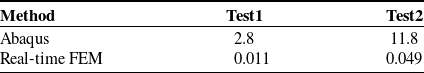
We used Abaqus to validate the accuracy of our real-time FEM solver. Abaqus is one of the most widely used and reliable commercial finite element analysis software packages, renowned for its accuracy and robustness. For this purpose, a scene containing a liver model was constructed, as illustrated in Fig. 6 and Fig. 7. In both simulations, the Young’s modulus and Poisson’s ratio were set to 1000 MPa and 0.3, respectively, and both the Abaqus simulation and our real-time FEM solver utilized the same mesh, consisting of 778 tetrahedral elements.
The results of the stress field in FEM simulation using (b) Abaqus and (c) real-time FEM. (a) shows the initial shape, (d) demonstrates the displacement of the node to which the force is applied.

The results of the stress field in FEM simulation using (b) Abaqus and (c) our method. (a) The simulation scene shows a cylinder moving upward to contact the liver. (d) illustrates the displacement of node No.17 in Abaqus and real-time FEM.

In the first test, a 100 n external grasping force was applied to node No.17 of the mesh. In the second test, a rigid cylinder was moved upward to contact the liver, causing deformation. Figure 6(b) and (c) show a comparison of the von Mises stress fields obtained from Abaqus and the real-time FEM solver, while Fig. 6(d) presents the displacement of the grasping node over time. A similar trend can be seen in Fig. 7(b) and (c) for the second test. These results demonstrate that our real-time FEM solver achieves high accuracy, closely matching the results produced by Abaqus.
To further evaluate the computational efficiency of our solver, we recorded the runtime of both methods, as summarized in Table I. The results show that our real-time FEM solver significantly outperforms Abaqus in terms of computational speed, while maintaining comparable accuracy. This demonstrates the feasibility and effectiveness of our method for real-time grasping planning.
Comparison of computational time (s) between Abaqus and real-time FEM.

5.2. Simulation results
To evaluate the performance of the proposed method, comprehensive simulation experiments are conducted. The targets for these simulations are generated using forward FEM simulations, where random forces are applied to the boundaries of the objects to emulate manipulations performed by surgeons. The optimal grasping points are then estimated using the proposed inverse FEM-based QP approach, and the resulting deformation is evaluated.
Two deformable objects are used for the simulation: an arbitrarily shaped tissue (Pha01) and a liver model (Pha02), as shown in Fig. 8. Pha01 consists of 2279 tetrahedron mesh elements, while Pha02 has 1330 elements. Both models are assigned material properties with Young’s modulus of
 $100$
kPa and a Poisson’s ratio of
$100$
kPa and a Poisson’s ratio of
 $0.3$
to simulate soft tissue behavior. For each object, 20 candidate grasping points are pre-defined on the surface. For the case of IOS, we evenly select 75 feature points on the surface. The feature error
$0.3$
to simulate soft tissue behavior. For each object, 20 candidate grasping points are pre-defined on the surface. For the case of IOS, we evenly select 75 feature points on the surface. The feature error
 $e_f$
and mean feature error
$e_f$
and mean feature error
 $e_s$
are used as performance metrics, defined as:
$e_s$
are used as performance metrics, defined as:
 \begin{equation} e_f = ||\boldsymbol{\delta }_f - \boldsymbol{\delta }_f^r||^2, \quad e_s = e_f/n_f \end{equation}
To validate the proposed method, forward FEM simulations are performed using the estimated grasping points, and the resulting feature errors are compared against those obtained using other candidate grasping points.
(a) and (c) are the objects used in simulation validation. (b) and (d) are the corresponding FE models. The fixed points are defined with a cyan box.

The proposed method is then used to estimate the optimal grasping points based on the target feature locations or point clouds, depending on the input type. For validation, forward FEM simulations are carried out using the identified grasping points, and the resulting deformations are compared against the target configurations. Additionally, the feature errors for all other candidate grasping points are computed, with the three lowest feature errors recorded for comparison. This process is repeated for both Pha01 and Pha02 across three trials for each input type. For each trial, different target deformations are assigned. Figure 9 shows the result of Pha01 with Fig. 10(a) and (b) demonstrating the case of IOK and IOS, respectively. Notably,
 $e_f$
and
$e_f$
and
 $e_s$
with the optimal grasping point are the lowest in all trials of both cases. A similar situation is seen in Fig. 10, which shows the result of Pha02. In a different structure, the proposed method is also capable of identifying the optimal grasping point.
$e_s$
with the optimal grasping point are the lowest in all trials of both cases. A similar situation is seen in Fig. 10, which shows the result of Pha02. In a different structure, the proposed method is also capable of identifying the optimal grasping point.
Simulation validation results of the tissue model. (a) The result of IOK case, (b) the result of IOS. The red line indicates the feature error with the identified optimal grasping point (GP), and the other lines represent the 3-first lowest feature errors from the candidate grasping points.

Simulation validation results of the liver model. (a) The result of the IOK case, (b) the result of the IOS. The red line indicates the feature error with the identified optimal grasping point (GP), and the other lines represent the 3-first lowest feature errors from the candidate grasping points.

Grasping location comparison with the proposed method and distance-based method. Columns (a)–(d) show the pictures of example trials. (e) presents the average terminal mean feature error (1: grasping position of the proposed method; 2: grasping position of the distance-based method.

For comparison, a distance-based method is implemented to determine the grasping location by identifying the largest distance between the initial shape and the target shape. We have proved that the distance-based method will lead to sub-optimal results in some cases because it does not consider the structural characteristics. To evaluate its performance against the proposed method, both approaches are tested using the same target inputs of IOS with 10 trials and share the same candidate grasping point set. The grasping points determined by each method are set as inputs of forward FEM simulations, and the resulting deformations are analyzed. The result is shown in Fig. 11, which demonstrates that the proposed method significantly outperforms the distance-based method. Specifically, our method achieved an average of 54% and 93% reduction of mean feature error for Pha01 and Pha02 scenarios, respectively.
Comparison validation between our method and distance-based method in dual-arm manipulation scenario. (a) The planning result of our method, and the selected grasping points are shown in red. (b) The mean feature error of manipulation results with grasping points planned by our method (in red) and by the distance-based method (in blue).

In dual-arm grasping scenarios, our method has been demonstrated to efficiently identify all grasping points in a single optimization step. To validate this capability, we conduct experiments using two grasping points with the point cloud as input, enabling a direct comparison with the distance-based method. For this evaluation, two random forces are applied to the FE model to generate the target point cloud, and the grasping points are then determined by each method. The results are illustrated in Fig. 12. Figure 12(a) demonstrates the computed
 $\Delta \boldsymbol{\lambda }_g$
values from QP optimization, where the candidate grasping points with the highest and second-highest values are selected. Figure 12(b) shows the mean feature error. The proposed method consistently identified grasping points near the locations where the forces are applied, resulting in significantly lower mean feature errors compared to the distance-based method.
$\Delta \boldsymbol{\lambda }_g$
values from QP optimization, where the candidate grasping points with the highest and second-highest values are selected. Figure 12(b) shows the mean feature error. The proposed method consistently identified grasping points near the locations where the forces are applied, resulting in significantly lower mean feature errors compared to the distance-based method.
6. Real-world experimental validation
To evaluate the proposed method in real-world scenarios, we conducted experiments involving a silicone liver phantom. Unlike the simulation experiments, the desired feature locations and point clouds are directly acquired from a depth camera. The experimental setup consists of four main components: a laparoscopic gripper, an Intel RealSense D435 depth camera, a silicone liver phantom, and a 6-DOF robotic manipulator. The depth camera is used for capturing the 3D point cloud of the deformed shape. The gripper is mounted on the end-effector of the robotic manipulator, enabling precise execution of the planned motions. The experimental setup can be seen in Fig. 1.
For the IOK experiments, colored markers are placed on the surface of the liver phantom to define the target feature locations. The desired configurations are generated by manually deforming the liver phantom while fixing the gripper at a random boundary position. The feature points are tracked using a combination of color-based segmentation in RGB images and depth measurements. These tracked positions are used as input for the inverse FEM-based optimization to determine the optimal grasping point. Once the grasping point is identified, the gripper is guided to the selected position. The computed motion
 $\Delta \boldsymbol{\delta }_g$
is applied to the robotic manipulator under position control. During deformation, the feature points are observed to converge rapidly toward their desired locations, as shown in Fig. 13.
$\Delta \boldsymbol{\delta }_g$
is applied to the robotic manipulator under position control. During deformation, the feature points are observed to converge rapidly toward their desired locations, as shown in Fig. 13.
Real-world experiment of manipulation in case of IOK. Column (a) shows the result of the planned grasping point (in green). Column (b) shows the deformation control result with the planned grasping point. The feature points are marked in red and blue circles. Column (c) shows the feature error. In each trial, the target deformation is different, while the set of candidate grasping points remains the same.

Real-world experiment with point cloud input and corresponding chamfer distance. We conduct 3 different trials shown in (a)–(c). In each trial, the target deformation is different, while the set of candidate grasping points remains the same. The planned grasping point is deployed in a real liver phantom, and the terminal point clouds are shown. The green dot indicates the grasping point. Point clouds in green and blue represent the target and terminal point clouds in deployment.

In the IOS experiments, the captured target shape is first registered with the FE model for 3D deformation tracking and 75 uniformly distributed feature points are selected on the surface of the FE model to represent the deformation. Since there is no constant direct correspondence between the feature points and the observed point cloud. Hence, the Chamfer distance, which computes the average distance of each point in one point cloud to the closest point in the other, is used to quantify the difference between the target and achieved point clouds. The point clouds are continuously captured at intervals of 0.1s during deformation, and the Chamfer distances are calculated to evaluate the accuracy of the deformation. As shown in Fig. 14, the terminal Chamfer distances for three trials are
 $1.18 \times 10^{-3}$
m,
$1.18 \times 10^{-3}$
m,
 $3.62 \times 10^{-3}$
m, and
$3.62 \times 10^{-3}$
m, and
 $1.29\times 10^{-3}$
m, demonstrating the high precision of the method in replicating the desired deformation.
$1.29\times 10^{-3}$
m, demonstrating the high precision of the method in replicating the desired deformation.
We note that our proposed framework is broadly applicable across practical surgical scenarios, including organ retraction, exposure of tumors or vessels, and training simulators with phantom tissues. A representative use case is deforming an organ into a surgeon-specified configuration to expose an underlying lesion, a step toward fully automated robotic assistance. To quantify effectiveness, we employ feature error and Chamfer distance to assess how closely the manipulated tissue matches the desired target shape; in practice, target shapes can be specified by the surgeon according to clinical needs.
7. Conclusion
In this paper, we propose an efficient grasping point selection framework for 3D soft tissue manipulation based on inverse FEM. By formulating the grasping task as a QP problem, our method enables the simultaneous identification of multiple optimal grasping points while accounting for the complex mechanical coupling within tissue structures. The proposed framework supports key points and point cloud inputs, providing flexibility for diverse surgical scenarios. Extensive simulation studies on different models demonstrated the effectiveness of our approach in selecting optimal grasping points in both single- and dual-arm manipulation tasks. Real-world experiments on a silicone liver phantom further validate the sim-to-real applicability and effectiveness of the framework.
There are several limitations to the current work. First, dual-arm manipulation is validated only in simulation, and real-world experiments are conducted on silicone phantoms. Second, the method relies on a quasi-static deformation assumption and may underperform for rapid or highly dynamic tissue motions. Third, the framework depends on an RGB-D camera for feature detection and has been evaluated only in open-cavity settings; extending it to minimally invasive/cavity surgery using endoscopic imaging remains future work. Looking ahead, we plan to handle dynamic tissue behavior by incorporating real-time feedback control and exploring integration into clinical surgical workflows. Additionally, experiments with in-vivo phantoms will be conducted to further validate the approach.
Author contributions
YD conducted the research and completed the manuscript. LL and ZZ provided guidance and reviewed the manuscript.
Financial support
This work is supported by InnoHK program.
Competing interest
The authors declare that no conflicts of interest exist.
Ethical approval
Not applicable.


 Open access