To save content items to your account,
please confirm that you agree to abide by our usage policies.
If this is the first time you use this feature, you will be asked to authorise Cambridge Core to connect with your account.
Find out more about saving content to .
To save content items to your Kindle, first ensure no-reply@cambridge.org
is added to your Approved Personal Document E-mail List under your Personal Document Settings
on the Manage Your Content and Devices page of your Amazon account. Then enter the ‘name’ part
of your Kindle email address below.
Find out more about saving to your Kindle.
Note you can select to save to either the @free.kindle.com or @kindle.com variations.
‘@free.kindle.com’ emails are free but can only be saved to your device when it is connected to wi-fi.
‘@kindle.com’ emails can be delivered even when you are not connected to wi-fi, but note that service fees apply.
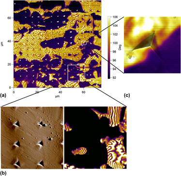
The local mechanical properties of ferritic and austenitic domains in a duplex stainless steel are locally studied by nanoindentation. The elastic and plastic properties of the two phases are determined. Without any specific surface treatment (chemical or electrochemical), the austenitic and ferritic domains present in the duplex stainless steel are distinguished using magnetic force microscopy. The magnetic scans allow nanoindentation results to be assigned to the respective phase, yielding the local mechanical properties of the duplex steel. The magnetic scans also show a sharp transition between the phases that is maintained even inside indentations. The ferrite phase is found to supersede austenite in the elastic modulus, hardness, and strain-hardening exponent, while both phases possess similar yield strength. Interface properties are a weighted average of the phase properties.
The spontaneous whisker growth phenomenon was investigated by exposing Sn3Nd intermetallic compound (IMC) to different environments. In a humid environment, tin whiskers grew rapidly; the incubation time for whisker formation was only 0.75 h. However, no whiskers were formed when Sn3Nd IMC was exposed to dry argon for 33 days or dry oxygen (DO) for 7 days. In situ observation of whisker growth during room ambient (RA) exposure gave an average whisker growth rate of the Sn3Nd IMC of about 11 Å/s, which are 2–3 orders of magnitude faster than that previously reported for tin plating. Following whisker growth, a new hydroxide compound, Nd(OH)3, was found to have formed on the Sn3Nd. The results show that the presence of humidity in the exposure environment is necessary for whisker growth from Sn3Nd. Finally, the driving force for whisker growth is also discussed.
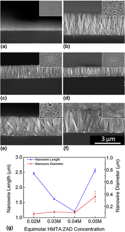
Hydrothermal approach is widely used for the synthesis of zinc oxide (ZnO) nanowires. Zinc nitrate hexahydrate, zinc acetate and zinc chloride are three common salts that are used for synthesis. Among these, zinc nitrate hexahydrate is primarily used in many studies and zinc chloride is preferred for electrodeposition. In this work, zinc acetate dihydrate salt is used for the growth of ZnO nanowires and the effects of time, temperature, solution concentration and concentration ratios of the precursor chemicals are investigated. It is found that the growth time and solution concentration control the lengths of the nanowires, whereas the precursor concentration ratio and solution concentration control their diameter. High solution concentrations and high zinc acetate dihydrate concentrations lead to the development of thin film morphology. Optimum growth parameters are obtained and suggested for the use of zinc acetate dihydrate as a zinc source for growing ZnO nanowires with high aspect ratio (AR). The use of zinc acetate dihydrate leads to the formation of ZnO nanowires without impurities and eliminates the need for using extra capping agents.
An interface can experience a number of different types of force, including chemical forces (e.g., due to compositional differences across the interface), curvature forces (due to interface curvature) and mechanical forces (Sutton and Balluffi, 2006; Asaro and Lubarda, 2006). In view of the focus of this book, I consider only mechanical forces.
In general, an interface experiences a mechanical force when it lies between two adjoining regions containing different elastic fields and therefore different strain energy densities and elastic displacement fields. In such cases movement of the interface, in which one region grows at the expense of the other, can produce a decrease in the overall energy of the body and thereby give rise to a force on the interface, expressed by Eq. (5.38). Such a force can occur under a variety of circumstances. For example, during the recrystallization of a plastically deformed crystalline body, relatively strain-free crystals form and then grow into the surrounding plastically deformed and dislocated matrix. Here, the reduction in energy that occurs as the strain-free crystals grow at the expense of the dislocated matrix produces outward forces on the interfaces bounding the strain-free crystals. In other situations, elastic fields that differ across interfaces, and therefore generate a mechanical interface force, often occur in polycrystalline materials in the form of compatibility stresses, arising as a result of elastic anisotropy, anisotropic thermal expansion, and differing modes of plastic deformation in the crystals adjoining the interfaces (e.g., Sutton and Balluffi, 2006).
An introduction to the use of anisotropic linear elasticity in determining the static elastic properties of defects in crystals is presented. The defects possess different dimensionalities and span the defect spectrum. They include:
Point defects (vacancies, self-interstitials, solute atoms, and small clusters of these species),
Line defects (dislocations),
Planar defects (homophase and heterophase interfaces),
Volume defects (inhomogeneities and inclusions).
To avoid confusion, an inclusion is defined as a misfitting region embedded within a larger constraining matrix body, and, therefore, acts as a source of stress. It may be either homogeneous (if it possesses the same elastic properties as the matrix) or inhomogeneous (if its elastic properties differ). On the other hand, an inhomogeneity is simply an embedded region with different elastic constants but no misfit.
The basic elements of anisotropic linear elasticity are presented in concise form. First, the deformation of an elastically strained body is described in terms of the local displacements, strains, and rotations that occur throughout the body. Requirements on the strains that ensure compatibility of the medium are then described. Next, the forces acting throughout the body are described in terms of surface tractions, body forces, and stresses. Conditions for mechanical equilibrium are derived. The stresses and strains are then linearly coupled via elastic constants, and various stress–strain relationships are derived. Finally, the energy stored in an elastically strained medium is formulated. Elements of the theory for the special case when the medium is elastically isotropic are included, along with several formulations of additional elastic quantities required for treating crystal defects.
References include: Love (1944); Sokolnikoff (1946); Muskhelishvili (1953); Nye (1957); Lekhnitskii (1963); Bacon, Barnett and Scattergood (1979b); Soutas-Little (1999); Hetnarski and Ignaczak (2004) and Asaro and Lubarda (2006).
To formulate interactions between defects and stress it is useful to classify the various types of defect and stress that will be of concern to us. Of the defects considered in this book, inclusions, point defects, dislocations, and various interfaces containing discrete intrinsic dislocations are sources of stress, and they therefore interact elastically with imposed stress, which may be internal stress due, for example, to the presence of other defects, or applied stress, due to forces applied to the body.
On the other hand, when a defect source of stress lies in a finite region bounded by interfaces, an image stress is generated, as described in Section 3.8, which then interacts with the defect. Thus, the interface acts, in a sense, as the source of a stress that interacts with the defect. In addition, an inhomogeneity, which by itself is not a source of stress, causes a perturbation of an imposed stress field, which, in turn, interacts with the imposed stress. An inhomogeneity may therefore be regarded as the indirect source of a stress that interacts with an imposed stress.
The fundamentals necessary to analyze the interaction energies and forces thatcan occur between the various defects treated in this book are now in place. Theelastic fields produced by the defects, and the interactions between the defectsand various elastic fields, have been formulated in previous chapters.
The general procedure for determining the interaction between two defects is toobtain the elastic field due to one defect at the location of the other and thento determine the interaction of the latter defect with this field. Since thenumber of possible defect–defect interactions is far too large toconsider comprehensively, this final chapter is restricted to a limited numberof representative interactions, which serve to demonstrate basic methods.
Point defect–point defect interactions
First, a general formulation is given of the interaction energy between two pointdefects that are represented by force multipoles, as in Chapters 10 and 11.Following this, the interaction between two point defects, each possessing cubicdefect symmetry, is analyzed for the case of an isotropic system.
General formulation
The interaction energy between a single point defect and a general elastic fieldhas been formulated in Chapter 11 (see Eqs. (11.1)–(11.4)), and the displacementfield due to a force multipole is given by Eq. (10.10). The interaction energybetween two point defects, i.e., D1 and D2, can therefore be obtained byimagining that D2 is created at the origin in the presence of D1 at theposition, x, and using the above results for the interaction energy and requiredelastic field.