To save content items to your account,
please confirm that you agree to abide by our usage policies.
If this is the first time you use this feature, you will be asked to authorise Cambridge Core to connect with your account.
Find out more about saving content to .
To save content items to your Kindle, first ensure no-reply@cambridge.org
is added to your Approved Personal Document E-mail List under your Personal Document Settings
on the Manage Your Content and Devices page of your Amazon account. Then enter the ‘name’ part
of your Kindle email address below.
Find out more about saving to your Kindle.
Note you can select to save to either the @free.kindle.com or @kindle.com variations.
‘@free.kindle.com’ emails are free but can only be saved to your device when it is connected to wi-fi.
‘@kindle.com’ emails can be delivered even when you are not connected to wi-fi, but note that service fees apply.
Amorphous zinc tin oxide (ZTO) was investigated to determine the effect of deposition and postannealing conditions on film structure, composition, surface contamination, and thin-film transistor (TFT) performance. X-ray diffraction results indicated that the ZTO films remain amorphous even after annealing to 600 °C. Rutherford backscattering spectrometry indicated that the bulk Zn:Sn ratio of the sputter-deposited films were slightly tin rich compared to the composition of the ceramic sputter target. X-ray photoelectron spectroscopy indicated that residual surface contamination depended strongly on the sample postannealing conditions where water, carbonate, and hydroxyl species were adsorbed to the surface. Electrical characterization of ZTO TFTs indicated that the best devices had mobilities of 17 cm2/Vs, threshold voltages of −1.5 V, subthreshold slopes of 0.9 V/dec, turn-on voltages of −12 V, and on-to-off ratio of >107. Annealing ZTO in vacuum assisted in the removal of adsorbed species, which may reduce defects in the films and improve device performance.
Indentation load–displacement curves for Mo (100) single crystals reveal clear displacement bursts from spherical indenters with various radii from ∼0.1 to ∼130 μm. There are two different size-dependent mechanisms for dislocation evolution involved during the displacement bursts. It has been postulated that these bursts are triggered by the nucleation of dislocations for a small indenter radius and the activation of preexisting dislocations for a large indenter radius. We present a simple model with which the displacement bursts from a larger indenter radius can be rationalized. This model relates the load and the excursion length during the first displacement burst. The correspondence between the model and experimental data indicates that the displacement bursts are initiated by the activation of preexisting dislocations and the model can accurately describe the mechanism for the displacement bursts from large indenters.
To enhance the reliability of Pb-free solders in high temperature and high humidity conditions, the minor alloying elements of Be and Co are investigated in terms of the growth of Sn whiskers and various properties of Sn-based Pb-free solders. Sn whisker growth is suppressed by adding up to 0.02 wt% Be to Sn-based solders. Adding Be and Co can effectively reduce the undercooling of Sn–1.0Ag–0.5Cu (wt%) solders. And the microstructures of Sn–1.0Ag–0.5Cu–0.02Be solders are similar to those of Sn–1.0Ag–0.5Cu. Furthermore, adding Co to solders increases the microhardness number as a result of the solid solution hardening. Adding Be causes no changes in the morphology or thickness of Cu6Sn5 at the Cu/OSP (organic solderability preservative) under bump metallurgy interface. However, the scallop-like Cu6Sn5 microstructure changes to a flat (Cu,Co)6Sn5 microstructure when 0.05 wt% of Co is added to Sn–1.0Ag–0.5Cu–0.02Be solders.
Nonstoichiometric mixed ionic and electronic conductors (MIECs) find use as oxygen permeation membranes, cathodes in solid oxide fuel cells, oxygen storage materials in three-way catalysts, and chemoresistive gas sensors. Praseodymium–cerium oxide (PrxCe1−xO2−δ) solid solutions exhibit MIEC behavior in a relatively high and readily accessible oxygen partial pressure () regime and as such serve as model systems for investigating the correlation between thermodynamic and kinetic properties as well as exhibiting high performance figures of merit in the above applications. In this paper, we extend recently published results for Pr0.1Ce0.9O2−δ to include values of x = 0, 0.002, 0.008, 0.1, and 0.20 (in PrxCe1−xO2−δ) to test how both defect and transport parameters depend on Pr fraction. Important observed trends with increasing x include increases in oxygen ion migration energy and MIEC and reductions in vacancy formation and Pr ionization energies. The implications these changes have for potential applications of PrxCe1−xO2−δ are discussed.
As explained in the previous chapter, damage affects the overall stress–strain response of the solid continuum body. Damage mechanics pertains to the study of this effect. Two widely different subfields have emerged over the years in this field. One concerns study of damage directly at the scale of formation of cracks, i.e., the microstructural scale, and hence can be called “micro-damage mechanics” (MIDM). The other approach, on the contrary, looks at the overall response at the macro or structural scale by using some internal variables to characterize damage, and thus can be termed as “macro-damage mechanics” (MADM). These terms were originally coined by Hashin [1]. MADM is the same as “continuum damage mechanics” (CDM), which is still the commonly used terminology.
MIDM for composite materials is derived from an older and more mature field called micromechanics that deals with overall properties of heterogeneous materials (see, e.g., [2]). In micromechanics one views heterogeneities such as inclusions and voids as “microstructure” and estimates overall properties by various methods, e.g., averaging schemes such as self-consistent and differential schemes, or variational methods to obtain bounds to average properties. Microcracks are treated as limiting geometry of microvoids, such as ellipsoidal voids with one dimension much smaller than the other two. As illustrated in the previous chapter, “damage” in composite materials has significant complexities concerning the geometry as well as evolution characteristics such as multiplication of cracks within a fixed volume. For these reasons a simple extension of micromechanics to damage in composites is generally not possible. A separate field identified as MIDM has therefore emerged. This chapter will treat the features of MIDM that have been developed to specifically treat certain cases of damage in composite materials. Since determining local (micro-level) stress or displacement fields is a necessary feature of micromechanics, it is expected that not all cases within the wide range of damage in composites can be handled by MIDM. However, this limitation can be alleviated by incorporating computational solutions of the local stress or displacement fields, thereby broadening classical micromechanics to include so-called computational micromechanics. In the most recent versions of MIDM this strategy has been used. More on this will be discussed toward the end of this chapter.
Phosphonated polysulfones in the acid form (PPSU-As) with degree of phosphonation (DP) = 0.4, 0.75, and 0.96 were successfully synthesized and utilized for the preparation of polymer blend with sulfonated poly(ether ether ketone) (SPEEK) having a degree of sulfonation (DS) = 75. The resulted blend membranes were characterized and investigated as new polyelectrolyte membrane for fuel cells applications. SPEEK/PPSU-A blend membranes formed ionic networks through hydrogen bonding bridges between the strong sulfonic acid groups and the amphoteric phosphonic acid groups. These ionic interactions resulted in enhanced membrane properties in terms of water swelling, methanol uptake, methanol permeability, mechanical strength, and thermal stability, without significant loss of proton conductivity. All the blend membranes were transparent to visible light with presence of microphases in the order of 10–20 nm. When compared to parent SPEEK membranes, the new SPEEK/PPSU-A blend membranes showed slightly lower methanol permeability compared to neat SPEEK membrane. Membranes with 30 wt% phosphonic acid content with DP = 0.75 and 0.96, exhibited slightly higher proton conductivities at temperatures above 50 °C in comparison with Nafion membrane.
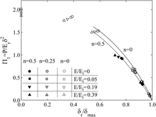
In the analysis of instrumented indentation data, it is common practice to incorporate the combined moduli of the indenter (Ei) and the specimen (E) in the so-called reduced modulus (Er) to account for indenter deformation. Although indenter systems with rigid or elastic tips are considered as equivalent if Er is the same, the validity of this practice has been questioned over the years. The present work uses systematic finite element simulations to examine the role of the elastic deformation of the indenter tip in instrumented indentation measurements and the validity of the concept of the reduced modulus in conical and pyramidal (Berkovich) indentations. It is found that the apical angle increases as a result of the indenter deformation, which influences in the analysis of the results. Based upon the inaccuracies introduced by the reduced modulus approximation in the analysis of the unloading segment of instrumented indentation applied load (P)–penetration depth (δ) curves, a detailed examination is then conducted on the role of indenter deformation upon the dimensionless functions describing the loading stages of such curves. Consequences of the present results in the extraction of the uniaxial stress–strain characteristics of the indented material through such dimensional analyses are finally illustrated. It is found that large overestimations in the assessment of the strain hardening behavior result by neglecting tip compliance. Guidelines are given in the paper to reduce such overestimations.
Time stability of the solid oxide fuel cells (SOFCs) has been a significant concern toward realization of their practical applications. Its operation at elevated temperatures and in oxidizing atmospheres makes the cathode current collector one of the most vulnerable components of the SOFCs. Silver and silver-based metal oxide [lanthanum–strontium manganite (LSM) and yttria-stabilized zirconia] composites were investigated for the development of low-cost current collectors with long-term stability. While densification of pure silver limited its use as current collector, incorporation of oxide particles to the silver matrix led to formation of porous composites. However, addition of YSZ particles did not result in a stable porosity. Analysis of the impedance spectra allowed further investigations on the obtained microstructures and the formed contacts. No microstructural degradation has been observed in the porous Ag–LSM composite current collector and its electrical properties remained stable for over 5000 h of measurements at 800 °C in air.
The field of composite materials has advanced steadily from the early developments during the 1970s when laminate plate theory and anisotropic failure criteria were in focus to today's diversification of composite materials to multifunctional and nanostructured composite morphologies. Throughout the 1970s and 1980s several books appeared along with courses that were developed and taught at advanced levels dealing with mechanics of composite materials and structures. The failure analysis was mostly limited to descriptions of strength that extended previous continuum descriptions of metal yielding and failure. Beginning around the mid-1980s, micromechanics and continuum damage mechanics were applied to multiple cracking observed in composite materials. Under the overall description of “damage mechanics” a flurry of activities took place as evidenced by conferences and symposia. Other than several conference proceedings that recorded such activities, a collection of seminal contributions to the field appeared in a volume (Damage Mechanics of Composite Materials, R. Talreja, ed., Composite Materials Series, R.B. Pipes, series ed., Vol. 9, Amsterdam: Elsevier Science Publishers, 1994). The two main avenues of approach to damage in composite materials and its effect on materials response, now referred to as micro-damage mechanics (MIDM) and macro-damage mechanics (MADM), were presented in a balanced form in that volume. In the years since then, many developments have taken place that have brought this field to such level of maturity that a book coherently presenting the material was felt to be timely. It is hoped that this book will help provide impetus for teaching advanced courses in composite damage at universities as well as support short courses for professional development of engineers in industry. The wealth of material covered can also help new researchers in advancing the field further. To this end, the last chapter provides some guidance in identifying gaps and needs for further work.
Physical and chemical properties of solid materials are modified by introducing defects, which disarrange the atomic periodic structure. Typical example is oxygen vacancies on titanium dioxide (TiO2) surfaces. Oxygen vacancies on TiO2 surfaces provide new physical and chemical surface properties, such as conductivity, catalytic activity, hydrophilicity, etc. To date, annealing, electron-/photo-stimulated desorption, and chemical reaction have been reported to create oxygen vacancies on TiO2 surfaces. However, these techniques do not allow position control of the defects at the atomic scale. We report the creation of single oxygen vacancy using a scanning tunneling microscope (STM). This technique creates oxygen vacancy at desired site. In addition, based on the experimental findings, we discuss the mechanism of manipulating atomic defects using the STM.
In this article, the sizes of the volumes sampled by nanoindentation tests for hardness and modulus measurements are studied using finite element simulations. The zones of influence for hardness and modulus in single-phase systems are determined by modeling a hemispherical particle in a matrix, with properties close to those of each other, and monitoring the deviation of the measured values from those of the particle. It is found that, for hardness testing of elastic-perfectly plastic materials, the intrinsic hardness of the particle is measured as long as the plastic region is still within the particle, i.e., the contact radius is one half or less of the particle radius. Thus, in a hardness test of a single-phase material, all of the plastically deforming material, and only the plastically deforming material, contributes to the hardness measured. In contrast, the zone influencing the modulus is not restricted to a specific volume near the indenter. The modulus measured from the elastic response at the indentation point is dependent upon the entire specimen. A relationship is developed to describe the observed behavior of the measured modulus, that holds true for both sink-in and pile-up material behavior and for different indenter cone angles.
In Chapter 1 we discussed the durability assessment of composite structures, theoverall goal for the subject of this book. As outlined there in Figure 1.1, themechanisms of damage and their effects on deformational response constitute themain thrust of the field of damage mechanics, which is at the core of durabilityassessment. After discussing the physical nature of damage observedexperimentally in Chapter 3, the next two chapters treated the two mainapproaches in damage mechanics – micro-damage mechanics (MIDM) andmacro-damage mechanics (MADM), both aimed at predicting deformational responseat fixed damage. Damage evolution was treated in Chapter 6, while Chapter 7 wasdevoted to fatigue, a subject that requires special attention due to theconceptual difficulties it poses.
In closing the book we wish in this chapter to review what has been achieved andwhat directions the field of damage and failure of composite materials shouldpursue to further advance toward durability assessment and beyond.
Computational structural analysis
Obviously, complex structural geometries require computational structuralanalysis. The analytical modeling of damage initiation and evolution, and itseffects on deformational response of composite laminates, discussed in previouschapters, were developed for idealized simple cases. Direct application of thesemodels is limited to structures with simple geometry and loading conditions. Forcomplex geometries, such as an airplane wing or a wind turbine blade, usuallysubjected to multi-axial mechanical loads, and possibly combined with thermaland moisture environments as well as manufacturing-induced residual stresses,computational approaches are inevitable. In industry, one often uses commercialsoftware, e.g., ANSYS, ABAQUS, and NASTRAN, and the obvious need is to integratedamage and failure analyses into these codes. Efforts have been made to attemptsome simple test cases where FE analysis of composites is combined with damageusing failure criteria [1]. A series of World Wide Failure Exercises (WWFE)[2–4] have been conducted to compare several composite failure models withexperimental data and provide guidance for their usage in composite design.
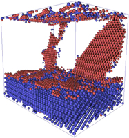
Forced chemical mixing during severe plastic deformation was investigated at Cu-Nb face-centered-cubic (fcc)/body-centered-cubic (bcc) interfaces using molecular-dynamics simulations. Three Cu-Nb interfaces were considered, with either Kurdjumov-Sachs or Nishiyama-Wassermann orientation relationship (OR) between fcc and bcc phases. Forced mixing of a spherical bcc-Nb precipitate in fcc-Cu was also studied for comparison. Deformation was imposed by shape-preserving cycles using two different modes, biaxial compression and biplanar shearing to investigate the effects of strain path. For biplanar shear, the chemical mixing rate is strongly dependent on structure of the interface, with the Kurdjumov-Sachs OR and a (111)Cu‖(110)Nb habit plane being particularly resistant to mixing. During compression, no such dependence was found. Influences of interface diffuseness and roughness on stability were also investigated. The simulations show the interface mixing is inversely related to interface shear strength during shear deformation, but dominated by dislocation-glide through the Cu phase and subsequent absorption at Cu-Nb interfaces during compression deformation.
All structures are designed for a purpose. If the purpose is to carry loads, then a designer must assure that the structure has sufficient load-bearing capacity. If the structure is to function over a period of time, then it must be designed to meet its functionality over that period without losing its integrity.
These are generic structural design issues irrespective of the material used. There are, however, significant differences in design procedures depending on whether the material used is a so-called monolithic material, e.g., a metal or a ceramic, or whether it is a composite material with distinctly different constituents. The heterogeneity of microstructure as well as the anisotropy of properties provide significantly different characteristics to composite materials in how they deform and fail when compared to metals or ceramics. This chapter will review those characteristics. However, before proceeding we need to introduce certain definitions.
Fracture: Conventionally, fracture is understood to be “breakage” of material, or at a more fundamental level, breakage of atomic bonds, manifesting itself in formation of internal surfaces. Examples of fracture in composites are fiber breakage, cracks in matrix, fiber/matrix debonds, and separation of bonded plies (delamination). The field known as fracture mechanics deals with conditions for formation and enlargement of the surfaces of material separation.
Damage: Damage, on the other hand, refers to a collection of all the irreversible changes brought about in a material by a set of energy dissipating physical or chemical processes, resulting from the application of thermomechanical loadings. Damage may inherently be manifested by atomic bond breakage. Unless specified differently, damage is understood to refer to distributed changes. Examples of damage in composites are multiple fiber-bridged matrix cracking in a unidirectional composite, multiple intralaminar cracking in a laminate, local delamination distributed in an interlaminar plane, and fiber/matrix interfacial slip associated with multiple matrix cracking. These damage mechanisms will be explained in some detail later in this chapter. The field of damage mechanics deals with conditions for initiation and progression of distributed changes as well as with consequences of those changes on the response of a material (and by implication, a structure) to external loading.